


|
|
|
|
|
|
|
|
|
|
|
|
Model |
|
C 7BMR |
Circular saw |
||
Modèle |
|
Scie circulaire |
|||
Modelo |
|
|
Sierra circular |
||
SAFETY INSTRUCTIONS AND INSTRUCTION MANUAL
 WARNING
IMPROPER OR UNSAFE use of this power tool can result in death or serious bodily injury!
This manual contains important information about product safety. Please read and understand this manual BEFORE operating the power tool. Please keep this manual available for other users and owners before they use the power tool. This manual should be stored in safe place.
INSTRUCTIONS DE SECURITE ET MODE D’EMPLOI
 AVERTISSEMENT
Une utilisation INCORRECTE OU DANGEREUSE de cet outil motorisé peut entraîner la mort ou de sérieuses blessures corporelles!
Ce mode d’emploi contient d’importantes informations à propos de la sécurité de ce produit. Prière de lire et de comprendre ce mode d’emploi AVANT d’utiliser l’outil motorisé. Garder ce mode d’emploi à la disponibilité des autres utilisateurs et propriétaires avant qu’ils utilisent l’outil motorisé. Ce mode d’emploi doit être conservé dans un endroit sûr.
INSTRUCCIONES DE SEGURIDAD Y MANUAL DE INSTRUCCIONES
 ADVERTENCIA
¡La utilización INAPROPIADA O PELIGROSA de esta herramienta eléctrica puede resultar en lesiones de gravedad o la muerte!
Este manual contiene información importante sobre la seguridad del producto. Lea y comprenda este manual ANTES de utilizar la herramienta eléctrica. Guarde este manual para que puedan leerlo otras personas antes de utilizar la herramienta eléctrica. Este manual debe ser guardado en un lugar seguro.
DOUBLE INSULATION
DOUBLE ISOLATION
AISLAMIENTO DOBLE

English
|
|
|
|
|
CONTENTS |
|
|
|
|||||
English |
|
|
|
|
|
|
Page |
||||||
|
|
|
|
|
Page |
ASSEMBLY AND OPERATION |
|||||||
|
|
|
|
|
|
||||||||
|
|
|
|
|
|
||||||||
IMPORTANT SAFETY INFORMATION .............. |
|
3 |
8 |
||||||||||
MEANINGS OF SIGNAL WORDS |
...................... |
|
|
3 |
APPLICATIONS ..................................................... |
8 |
|||||||
SAFETY |
|
|
|
3 |
PRIOR TO OPERATION ......................................... |
8 |
|||||||
|
|
|
ADJUSTING THE SAW PRIOR TO USE |
9 |
|||||||||
GENERAL SAFETY RULES |
|
|
|
3 |
|||||||||
|
|
|
CUTTING PROCEDURES |
10 |
|||||||||
SAFETY INSTRUCTIONS FOR ALL SAWS |
|
4 |
|||||||||||
|
MOUNTING AND DISMOUNTING THE |
|
|||||||||||
FURTHER SAFETY INSTRUCTIONS FOR ALL |
|
|
|
||||||||||
|
|
|
SAW BLADE |
12 |
|||||||||
SAWS |
|
|
|
5 |
|
||||||||
|
|
|
MAINTENANCE AND INSPECTION |
13 |
|||||||||
SAFETY INSTRUCTIONS FOR SAWS WITH |
|
|
|
||||||||||
INNER PENDULOM GOARD ......................... |
|
|
|
5 |
ACCESSORIES |
14 |
|||||||
DIFINITION FOR SYMBOLS USED ON THIS |
|
|
|
||||||||||
|
|
|
STANDARD ACCESSORIES |
14 |
|||||||||
TOOL |
|
|
|
6 |
|||||||||
|
|
|
OPTIONAL ACCESSORIES |
14 |
|||||||||
DOUBLE INSULATION FOR SAFER |
|
|
|
||||||||||
|
|
|
PARTS LIST |
39 |
|||||||||
OPERATION ................................................... |
|
|
|
6 |
|||||||||
FUNCTIONAL DESCRIPTION .................................... |
|
|
|
7 |
|
|
|
|
|
||||
NAME OF PARTS .................................................. |
|
|
|
7 |
|
|
|
|
|
||||
SPECIFICATIONS .................................................. |
|
|
|
7 |
|
|
|
|
|
||||
|
|
|
|
|
|
|
|
||||||
|
|
|
|
|
|
||||||||
|
|
|
TABLE DES MATIERES |
|
|
||||||||
Français |
|
|
|
|
|||||||||
|
|
|
|
|
|
|
|
|
|
|
|||
|
|
|
|
|
|
Page |
|
|
|
|
Page |
||
INFORMATIONS IMPORTANTES |
|
|
|
DESCRIPTION FONCTIONNELLE |
|||||||||
|
|
|
|
|
19 |
||||||||
DE SÉCURITÉ ............................................... |
|
|
|
15 |
NOM DES PARTIES ............................................ |
19 |
|||||||
SIGNIFICATION DES MOTS |
|
|
|
|
|
SPECIFICATIONS ................................................ |
19 |
||||||
D’AVERTISSEMENT .................................... |
|
|
|
15 |
ASSEMBLAGE ET FONCTIONNEMENT |
20 |
|||||||
SECURITE |
|
|
|
15 |
|||||||||
|
|
|
APPLICATIONS |
20 |
|||||||||
RÈGLES GENERALE DE SÉCURITÉ |
|
15 |
|||||||||||
|
AVANT L’UTILISATION |
20 |
|||||||||||
CONSIGNES DE SÉCURITÉ RELATIVES À |
|
|
|
||||||||||
|
|
|
RÉGLAGE DE LA SCIE AVANT |
|
|||||||||
TOUTES LES SCIES |
|
|
|
17 |
|
||||||||
|
|
|
|
L’UTILISATION |
21 |
||||||||
CONSIGNES DE SÉCURITÉ COMPLÉMENTAIRES |
|
||||||||||||
PROCEDURES DE COUPE |
22 |
||||||||||||
RELATIVES À TOUTES LES SCIES |
|
17 |
|||||||||||
|
MONTAGE ET DÉMONTAGE DE LA LAME DE |
||||||||||||
CONSIGNES DE SÉCURITÉ RELATIVES AUX |
|
|
|||||||||||
|
|
|
SCIE |
24 |
|||||||||
SCIES AVEC PROTECTEUR À PENDULE |
|
|
|
||||||||||
|
|
ENTRETIEN ET INSPECTION |
25 |
||||||||||
INTERNE ....................................................... |
|
|
|
18 |
|||||||||
DÉFINITIONS POUR LES SYMBOLES UTILISÉS |
ACCESOIRES |
26 |
|||||||||||
SUR CET OUTIL |
|
|
|
18 |
|||||||||
|
|
|
ACCESSOIRES STANDARD |
26 |
|||||||||
DOUBLE ISOLATION POUR UN |
|
|
|
|
|
||||||||
|
|
|
|
|
ACCESSOIRES EN OPTION |
26 |
|||||||
FONCTIONNEMENT PLUS SUR |
|
18 |
|||||||||||
|
|
|
|
|
|
||||||||
|
|
|
|
|
|
|
|
LISTE DES PIECES ................................................... |
39 |
||||
|
|
|
|
|
|
|
|
|
|
|
|||
|
|
|
|
|
|
|
|
|
|
||||
|
|
|
|
|
|
|
ÍNDICE |
|
|
|
|
||
Español |
|
|
|
|
|
|
|
Página |
|||||
|
|
|
|
|
|
|
|
|
|
||||
|
|
Página |
DESCRIPCIÓN FUNCIONAL |
||||||||||
|
|
|
|
|
|||||||||
INFORMACIÓN IMPORTANTE SOBRE |
|
|
|
31 |
|||||||||
SEGURIDAD ................................................. |
|
|
|
27 |
NOMENCLATURA ............................................... |
31 |
|||||||
SIGNIFICADO DE LAS PALABRAS DE |
|
|
|
ESPECIFICACIONES ............................................ |
31 |
||||||||
SEÑALIZACIÓN ............................................ |
|
|
|
27 |
MONTAJE Y OPERACIÓN |
32 |
|||||||
SEGURIDAD |
|
|
|
|
|
||||||||
|
|
|
27 |
APLICACIONES ................................................... |
32 |
||||||||
NORMAS GENERALES DE SEGURIDAD ........... |
|
27 |
ANTES DE LA OPERACIÓN ................................ |
32 |
|||||||||
INSTRUCCIONES DE SEGURIDAD PARA TODAS |
AJUSTE DE LA SIERRA ANTES DE |
|
|||||||||||
LAS SIERRAS ............................................... |
|
|
|
29 |
|
UTILIZARLA .................................................. |
33 |
||||||
INSTRUCCIONES DE SEGURIDAD ADICIONALES |
PROCEDIMIENTOS DE CORTE .......................... |
34 |
|||||||||||
PARA TODAS LAS SIERRAS ....................... |
|
|
|
29 |
MONTAJE Y DESMONTAJE DE LA |
|
|||||||
INSTRUCCIONES DE SEGURIDAD PARA |
|
|
|
|
CUCHILLA DE LA SIERRA ........................... |
36 |
|||||||
SIERRASCON UN PROTECTOR DE |
|
|
|
MANTENIMIENTO E INSPECCIÓN |
37 |
||||||||
PÉNDULO INTERNO |
|
|
|
30 |
|||||||||
|
|
|
|
|
|
|
|
||||||
DEFINICIONES PARA LOS SÍMBOLOS |
|
|
|
ACCESORIOS ........................................................... |
38 |
||||||||
UTILIZADOS EN ESTA HERRAMIENTA ...... |
|
30 |
ACCESORIOS ESTÁNDAR ................................. |
38 |
|||||||||
AISLAMIENTO DOBLE PARA OFRECER UNA |
|
|
ACCESORIOS OPCIONALES .............................. |
38 |
|||||||||
OPERACIÓN MÁS SEGURA ........................ |
|
|
|
30 |
LISTA DE PIEZAS |
39 |
|||||||
|
|
|
|
|
|
|
|
||||||
|
|
|
|
|
|
|
|
|
|
|
|
|
|
2

English
IMPORTANT SAFETY INFORMATION
Read and understand all of the safety precautions, warnings and operating instructions in the Instruction Manual before operating or maintaining this power tool.
Most accidents that result from power tool operation and maintenance are caused by the failure to observe basic safety rules or precautions. An accident can often be avoided by recognizing a potentially hazardous situation before it occurs, and by observing appropriate safety procedures.
Basic safety precautions are outlined in the “SAFETY” section of this Instruction Manual and in the sections which contain the operation and maintenance instructions.
Hazards that must be avoided to prevent bodily injury or machine damage are identified by WARNINGS on the power tool and in this Instruction Manual.
NEVER use this power tool in a manner that has not been specifically recommended by HITACHI.
MEANINGS OF SIGNAL WORDS
WARNING indicates a potentially hazardous situations which, if ignored, could result in death or serious injury.
CAUTION indicates a potentially hazardous situations which, if not avoided, may result in minor or moderate injury, or may cause machine damage.
NOTE emphasizes essential information.
SAFETY
GENERAL SAFETY RULES
 WARNING:
Read all instructions
Failure to follow all instructions listed below may result in electric shock, fire and/or serious injury.
The term “power tool” in all of the warnings listed below refers to your mains-operated (corded) power tool or battery-operated (cordless) power tool.
SAVE THESE INSTRUCTIONS
1)Work area safety
a)Keep work area clean and well lit.
Cluttered or dark areas invite accidents.
b)Do not operate power tools in explosive atmospheres, such as in the presence of flammable liquids, gases or dust.
Power tools create sparks which may ignite the dust of fumes.
c)Keep children and bystanders away while operating a power tool.
Distractions can cause you to lose control.
2)Electrical safety
a)Power tool plugs must match the outlet. Never modify the plug in any way.
Do not use any adapter plugs with earthed (grounded) power tools.
Unmodified plugs and matching outlets will reduce risk of electric shock.
b)Avoid body contact with earthed or grounded surfaces such as pipes, radiators, ranges and refrigerators.
There is an increased risk of electric shock if your body is earthed or grounded.
c)Do not expose power tools to rain or wet conditions.
Water entering a power tool will increase the risk of electric shock.
d)Do not abuse the cord. Never use the cord for carrying, pulling or unplugging the power tool.
Keep cord away from heat, oil, sharp edges or moving parts.
Damaged or entangled cords increase the risk of electric shock.
e)When operating a power tool outdoors, use an extension cord suitable for outdoor use.
Use of a cord suitable for outdoor use reduces the risk of electric shock.
3)Personal safety
a)Stay alert, watch what you are doing and use common sense when operating a power tool. Do not use a power tool while you are tired or under the influence of drugs, alcohol or medication.
A moment of inattention while operating power tools may result in serious personal injury.
3

English
b)Use safety equipment. Always wear eye protection.
Safety equipment such as dust mask, nonskid safety shoes, hard hat, or hearing protection used for appropriate conditions will reduce personal injuries.
c)Avoid accidental starting. Ensure the switch is in the off position before plugging in.
Carrying power tools with your finger on the switch or plugging in power tools that have the switch on invites accidents.
d)Remove any adjusting key or wrench before turning the power tool on.
A wrench or a key left attached to a rotating part of the power tool may result in personal injury.
e)Do not overreach. Keep proper footing and balance at all times.
This enables better control of the power tool in unexpected situations.
f)Dress properly. Do not wear loose clothing or jewellery. Keep your hair, clothing and gloves away from moving parts.
Loose clothes, jewellery or long hair can be caught in moving parts.
g)If devices are provided for the connection of dust extraction and collection facilities, ensure these are connected and properly used.
Use of these devices can reduce dust-related hazards.
4)Power tool use and care
a)Do not force the power tool. Use the correct power tool for your application.
The correct power tool will do the job better and safer at the rate for which it was designed.
b)Do not use the power tool if the switch does not turn it on and off.
Any power tool that cannot be controlled with the switch is dangerous and must be repaired.
c)Disconnect the plug from the power source and/or the battery pack from the power tool before making any adjustments, changing accessories, or storing power tools.
Such preventive safety measures reduce the risk of starting the power tool accidentally.
d)Store idle power tools out of the reach of children and do not allow persons unfamiliar with the power tool or these instructions to operate the power tool.
Power tools are dangerous in the hands of untrained users.
e)Maintain power tools. Check for misalignment or binding of moving parts, breakage of parts and any other condition that may affect the power tools operation. If damaged, have the power tool repaired before use.
Many accidents are caused by poorly maintained power tools.
f)Keep cutting tools sharp and clean.
Properly maintained cutting tools with sharp cutting edges are less likely to bind and are easier to control.
g)Use the power tool, accessories and tool bits etc., in accordance with these instructions and in the manner intended for the particular type of power tool, taking into account the working conditions and the work to be performed.
Use of the power tool for operations different from intended could result in a hazardous situation.
5)Service
a)Have your power tool serviced by a qualified repair person using only identical replacement parts.
This will ensure that the safety of the power tool is maintained.
–WARNING–
To reduce the risk of injury, user must read instruction manual.
SAFETY INSTRUCTIONS FOR ALL SAWS
DANGER!
a)Keep hands away from cutting area and the blade. Keep your second hand on auxiliary handle, or motor housing.
If both hands are holding the saw, they cannot be cut by the blade.
b)Do not reach underneath the workpiece.
The guard cannot protect you from the blade below the workpiece.
c)Adjust the cutting depth to the thickness of the workpiece.
Less than a full tooth of the blade teeth should be visible below the workpiece.
d)Never hold piece being cut in your hands or across your leg. Secure the workpiece to a stable platform.
It is important to support the work properly to minimize body exposure, blade binding, or loss of control.
e)Hold power tool by insulated gripping surfaces when performing an operation where the cutting tool may contact hidden wiring or its own cord.
Contact with a “live” wire will also make exposed metal parts of the power tool “live” and shock the operator.
f)When ripping always use a rip fence or straight edge guide.
This improves the accuracy of cut and reduces the chance of blade binding.
4

English
g)Always use blades with correct size and shape (diamond versus round) of arbour holes.
Blades that do not match the mounting hardware of the saw will run eccentrically, causing loss of control.
h)Never use damaged or incorrect blade washers or bolt.
The blade washers and bolt were specially designed for your saw, for optimum performance and safety of operation.
Never use any abrasive wheels
Burst of abrasive wheel cause serious injury of operator or persons around the working area.
FURTHER SAFETY INSTRUCTIONS FOR ALL SAWS
Causes and operator prevention of kickback:
d)Support large panels to minimize the risk of blade pinching and kickback.
Large panels tend to sag under their own weight. Supports must be placed under the panel on both sides, near the line of cut and near the edge of the panel.
e)Do not use dull or damaged blades.
Unsharpened or improperly set blades produce narrow kerf causing excessive friction, blade binding and kickback.
f)Blade depth and bevel adjusting locking levers must be tight and secure before making cut.
If blade adjustment shifts while cutting, it may cause binding and kickback.
g)Use extra caution when making a “plunge cut” into existing walls or other blind areas.
The protruding blade may cut objects that can cause kickback.
–Kickback is a sudden reaction to a pinched, bound
or misaligned saw blade, causing an uncontrolled SAFETY INSTRUCTIONS FOR SAWS WITH
saw to lift up and out of the workpiece toward the operator.
–When the blade is pinched or bound tightly by the kerf closing down, the blade stalls and the motor reaction drives the unit rapidly back toward the operator.
–If the blade becomes twisted or misaligned in the cut, the teeth at the back edge of the blade can dig into the top surface of the wood causing the blade to climb out of the kerf and jump back toward the operator.
Kickback is the result of saw misuse and/or incorrect operating procedures or conditions and can be avoided by taking proper precautions as given below.
a)Maintain a firm grip with both hands on the saw and position your arms to resist kickback forces. Position your body to either side of the blade, but not in line with the blade.
Kickback could cause the saw to jump backwards, but kickback forces can be controlled by the operator, if proper precautions are taken.
b)When blade is binding, or when interrupting a cut for any reason, release the trigger and hold the saw motionless in the material until the blade comes to a complete stop.
Never attempt to remove the saw from the work or pull the saw backward while the blade is in motion or kickback may occur.
Investigate and take corrective actions to eliminate the cause of blade binding.
c)When restarting a saw in the workpiece, centre the saw blade in the kerf and check that saw teeth are not engaged into the material.
If saw blade is binding, it may walk up or kickback from the workpiece as the saw is restarted.
INNER PENDULUM GUARD
a)Check lower guard for proper closing before each use. Do not operate the saw if lower guard does not move freely and close instantly. Never clamp or tie the lower guard into the open position.
If saw is accidentally dropped, lower guard may be bent.
Raise the lower guard with the retracting handle and make sure it moves freely and does not touch the blade or any other part, in all angles and depth of cut.
b)Check the operation of the lower guard spring. If the guard and the spring are not operating properly, they must be serviced before use.
Lower guard may operate sluggishly due to damaged parts, gummy deposits, or build-up of debris.
c)Lower guard should be retracted manually only for special cuts such as “plunge cuts” and “compound cuts”. Raise lower guard by retracting handle and as soon as blade enters the material, the lower guard must be released.
For all other sawing, the lower guard should operate automatically.
d)Always observe that the lower guard is covering the blade before placing saw down on bench or floor.
An unprotected, coasting blade will cause the saw to walk backwards, cutting whatever is in its path. Be aware of the time it takes for the blade to stop after switch is released.
5

English
DEFINITIONS FOR SYMBOLS USED ON THIS TOOL
V ................. |
volts |
Hz ............... |
hertz |
A ................ |
amperes |
no ........................ |
no load speed |
.............. |
Class II Construction |
---/min ........ |
revolutions or reciprocation per minute |
............... |
alternating or direct current |
DOUBLE INSULATION FOR SAFER OPERATION
To ensure safer operation of this power tool, HITACHI has adopted a double insulation design. “Double insulation” means that two physically separated insulation systems have been used to insulate the
electrically conductive materials connected to the power supply from the outer frame handled by the operator. Therefore, either the symbol “ ” or the words “Double insulation” appear on the power tool or on the nameplate. Although this system has no external grounding, you must still follow the normal electrical safety precautions given in this Instruction Manual, including not using the power tool in wet environments.
To keep the double insulation system effective, follow these precautions:
Only HITACHI AUTHORIZED SERVICE CENTER should disassemble or assemble this power tool, and only genuine HITACHI replacement parts should be installed.
Clean the exterior of the power tool only with a soft cloth moistened with soapy water, and dry thoroughly.
Never use solvents, gasoline or thinners on plastic components; otherwise the plastic may dissolve.
SAVE THESE INSTRUCTIONS
AND
MAKE THEM AVAILABLE TO OTHER USERS
AND
OWNERS OF THIS TOOL!
6
English
FUNCTIONAL DESCRIPTION
NOTE:
The information contained in this Instruction Manual is designed to assist you in the safe operation and maintenance of the power tool.
NEVER operate, or attempt any maintenance on the tool unless you have first read and understood all safey instructions contained in this manual.
Some illustrations in this Instruction Manual may show details or attachments that differ from those on your own power tool.
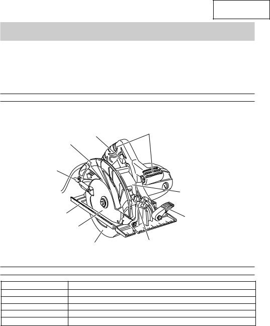
NAME OF PARTS
|
Handle |
Switch |
(Insulated gripping surface) |
|
|
Blade cover |
|
Lever |
|
(Retracting |
|
handle) |
|
|
Gear cover |
Base |
Lever (A) |
|
|
Saw blade |
|
Lower guard |
Lock lever |
|
|
|
Fig. 1 |
SPECIFICATIONS |
|
Motor |
Single-Phase, Series Commutator Motor |
Power Source |
Single-Phase 120V AC 60Hz, 120V DC |
Max. Cutting Depth |
2-3/8" (60mm) |
Current |
15 A |
No-Load Speed |
5,800/min. |
Weight (without cord) |
10.5 lbs (4.8 kg) |
7
English
ASSEMBLY AND OPERATION
APPLICATIONS
Cutting Various types of wood.
PRIOR TO OPERATION
1.Power source
Ensure that the power source to be utilized conforms to the power source requirements specified on the product nameplate.
2.Power switch
Ensure that the switch is in the OFF position. If the plug is connected to a receptacle while the switch is in the ON position, the power tool will start operating immediately and can cause serious injury.
3.Extension cord
When the work area is far away from the power source, use an extension cord of sufficient thickness and rated capacity. The extension cord should be kept as short as practicable.
 WARNING:
Damaged cord must be replaced or repaired.
4.Check the receptacle
If the receptacle only loosely accepts the plug, the receptacle must be repaired. Contact a licensed electrician to make appropriate repairs.
If such a faulty receptacle is used, it may cause overheating, resulting in a serious hazard.
5.Confirming condition of the environment:
Confirm that the work site is placed under appropriate conditions conforming to prescribed precautions.
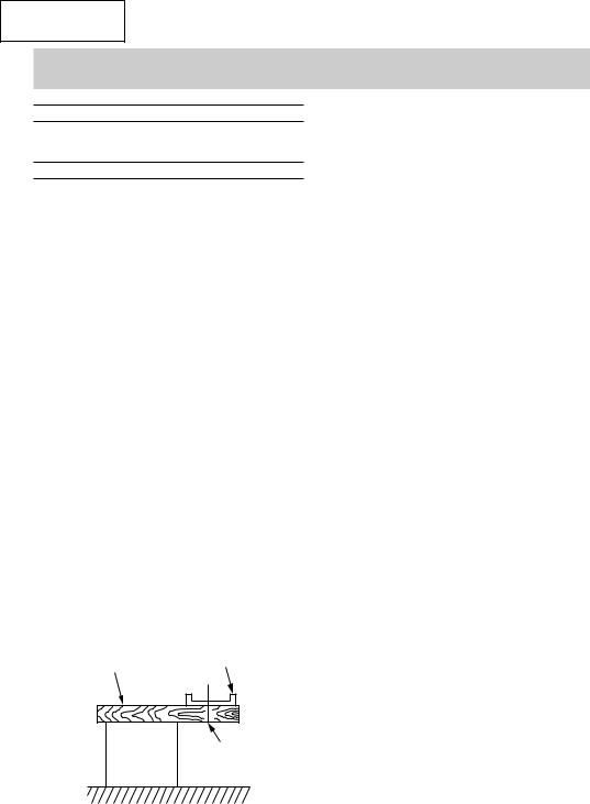
6.Prepare a wooden workbench (Fig. 2)
Since the saw blade will extend beyond the lower surface of the work piece, place the work piece on a workbench when cutting. If a square block is utilized as a workbench, select level ground to ensure it is properly stabilized. An unstable workbench will result in hazardous operation.
Work piece |
Base |
|
Workbench |
Saw blade |
 CAUTION:
To avoid possible accident, always ensure that the portion of work piece remaining after cutting is securely anchored or held in position.
7.Check if lever (A)s are tightened.
If the lever (A) to adjust cutting depth (Fig. 3) and lever (A) to adjust angle of inclination (Fig. 4) are loose, injury can result. Make sure that they are tightened securely.
8.Check performance of safety cover
 WARNING:
Make absolutely sure that the safety cover is not fixed. Also, check and see if it can move smoothly. If the saw blade is kept exposed injury can result.
The lower guard (refer to Fig. 1) serves to protect your body from coming into contact with the saw blade. Make absolutely certain that the cover smoothly performs to cover the saw blade. If the safety cover should not move smoothly, never use it without repairing it.
In such a case, get in touch with the store where you bought the circular saw or the HITACHI Authorized Service Center for necessary repair.
9.Eye protection
When you use the tool, make certain that you wear eye protection.
10.Check if saw blade is tightened
Refer to [mounting and dismounting the saw blade] in Page 12, and make sure that the flange bolt is tightened securely.
11.Check for proper operation of the brake.
Your saw has an automatic electric brake which is designed to stop the blade from coasting in about 3 seconds, after you release the trigger switch. It is useful when making certain cuts in wood where a coasting blade would result a wide imprecise cut. Occasionally, under certain conditions, the brake will not function properly and won't stop the saw in the 3 seconds discussed above.
If this condition persists, turn the saw on and off four or five times. If the brake still does not stop the blade in about 3 seconds, the problem may be worn brushes. Replace the brushes and try the saw again. If the problem still persists, have the tool serviced at a HITACHI AUTHRIZED SERVICE CENTER.
Fig. 2
8
English
ADJUSTSING THE SAW PRIOR TO USE
 WARNING:
To avoid serious accidents, ensure the switch is in OFF position, and disconnect the plug from the receptacle.
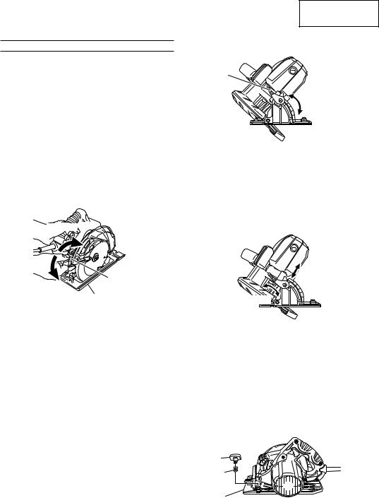
1.Adjusting the cutting depth (Fig. 3)
 WARNING:
If the lever (A) is loose, injury can result. Tighten it securely after adjustment.
To adjust cutting depth, loosen the lever (A) and, while holding the base with one hand, move the main body up and down to obtain the prescribed cutting depth. After adjusting to the prescribed cutting depth, tighten the lever (A) securely.
Loosen

Lever (A)
Tighten
Base
Fig. 3
2.Adjusting the angle of inclination
 WARNING:
If the lever (A) is loose, injury can result. Tighten it securely after adjustment.
You can incline saw blade from 0˚ to a maximun angle of 55˚ in relation to the base.
As shown in Fig. 4 by loosing the lever (A) on the bevel scale, the saw blade may be inclined to an angle of 45˚ in relation to the base.
Lever (A)
0˚ – 45˚
Fig. 4
If you use inclination angle of over 45˚, as shown in Fig. 5 move the lever (A) to inside, the saw blade may be inclined to a maximum angle of 55˚ in relation to the base.
Always ensure that the lever (A) is thoroughly tightened after making the desired adjustment.
45˚ – 55˚
Fig. 5
3.Regulating the guide (Rip fence) (Fig. 6, 7)
................................................ Optional Accessory
Install the wing bolt (B) and lock spring on the base. Insert the guide into the base, move it left and right and adjust the cutting position. Tighten the wing bolt (B) and fix the guide. The guide can be installed either from the left or the right side of the main body.
Wing bolt (B)
Lock spring
Base
Fig. 6
9

English
Wing bolt (B), Lock spring
Base
Guide (Rip fence)
Fig. 7
CUTTING PROCEDURES
 WARNING:
●Do not use any abrasive wheels.
●Never touch the moving parts.
●As shown in Fig. 8, be sure to hold the round handle securely with both hands when cutting. Contact with "live" wire will make exposed metal parts of the power tool "live" and shock the operator. In addition, make sure to secure the work piece with a clamp when cutting.
Fig. 8
●Should the saw blade be stopped or make an abnormol noise during operation, turn off the switch immediately.
●Don't remove circular saw from work piece during a cut while the saw blade is moving.
●Support large panels to minimize the risk of blade pinching and KICKBACK. Large panels tend to sag under their own weight. Supports must be placed under the panel on both sides, near the line of cut and near the edge of the panel as shown in Fig. 9. To minimize the risk of blade pinching and kickback. When cutting operation requires the resting of the saw on the work piece, the saw shall be rested on the larger portion and the smaller piece cut off.
To avoid kickback, do support board or panel near the cut.
Fig. 9
Don't support board or panel away from the cut.
Fig. 10
●Place the wider portion of the saw base on that part of the work piece which is solidly supported, not on the section that will fall off when the cut is made. As examples, Fig. 11 illustrates the RIGHT way to cut off the end of board, and Fig. 12 the WRONG way. If the work piece is short or small, clamp it down.
DON’T TRY TO HOLD SHORT PLACES BY HAND!
Fig. 11
10
English
Fig. 12
●Wear eye protection.
●Avoid cutting any material like metal, etc., that give off sparks.
 CAUTION:
●Always take care in preventing the power cord from coming near the revolving saw blade.
●Before starting to saw, ensure that the saw blade has reached full speed revolution.
1.Place the saw body (base) on the work piece, and as in Fig. 13 align the intended line of cut with the saw blade, using the notch at the front of the base. This relationship of base to work pieces should remain unchanged regardless of the inclination of the base.
When |
When not |
||||||||||
Inclined |
|||||||||||
Inclined 45° |
|
|
|||||||||
|
|
|
|
||||||||
|
|
|
|
|
|
|
|
|
|
|
|
|
|
|
|
|
|
|
|
|
|
|
|
|
|
|
|
|
|
|
|
|
|
|
|
|
|
|
|
|
|
|
|
|
|
|
|
Fig. 13
2.The switch should be turned to the ON position before the saw blade comes into contact with the work piece. The switch is turned ON when the trigger is pulled by one’s finger, and is turned OFF when the trigger is released.
3.Moving the saw straight at a constant speed will produce optimum cutting.
[POCKET CUTTING]
 WARNING:
●To avoid serious accident, ensure the switch is OFF position, and disconnect the plug from the receptacle before any adjustment.
●Never tie or wedge the lower guard in a raised position.
1.Mark the desired cutting area clearly with lines all side. (See Fig. 14)
2.Set depth adjustment according to material to be cut.
3.Push the lever all the way back so the blade is exposed as shown in Fig. 14.
Lever
Fig. 14
4.Tilt saw forward and align the notch (Fig. 13) with the pre-marked guide line.
5.Release the lever. When the lower guard contacts the work piece surface, it will be in proper position to open freely when cutting is commencend.
6.Holding the saw in position, with the blade not contacting the work piece surface, pull the trigger.
7.After the saw has reached full speed, gradually lower rear end of the saw until its base rests on the work surface.
8.Advance saw along the cutting line up to the corner.
9.Release trigger and allow blade to stop completely
before withdrawing the blade from the work piece.
Never under any circumstances pull the saw backwards while the blade is in motion, as kickback may result.
10.Use a jig saw or hand saw to cut the corners out clean.
11.When starting each new cut, repeat as above.
11
English
MOUNTING AND DISMOUNTING THE SAW BLADE
 WARNING:
To avoid serious accident ensure the switch is in the OFF position, and disconnect the plug from the receptacle.
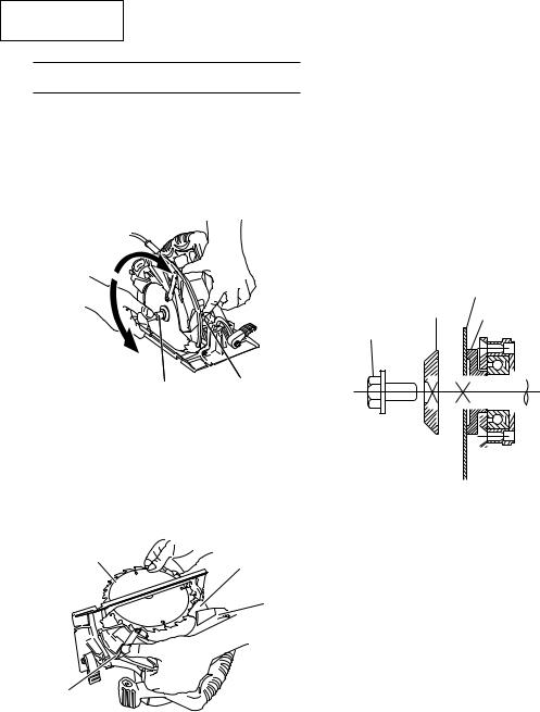
1.Dismounting the saw blade
(1)Set the cutting volume at maximum, and place the Circular Saw as shown in Fig. 15.
Tighten
Loosen
Wrench |
Lock lever |
Fig. 15
(2)Depress the lock lever, lock the spindle, and remove the hexagonal-flange bolt and washer(B) with the wrench.
(3)While holding the lever to keep the lower guard fully retracted into the blade cover, remove the saw blade. (Fig. 16)
2.Mounting the saw blade
(1)Thoroughly remove any sawdust which has accumulated on the spindle, bolt and washers.
(2)For mounting saw blade, the concave sides of both washers (A) and (B) must be fitted to the saw blade sides. Mount the saw blade on the spindle, and finally affix washer (B) (See Fig. 17)
(3)To assure proper rotation direction of the saw blade, the arrow direction on the saw blade must coincide with the arrow direction on the blade cover.
(4)Using the fingers, tighten the hexagonal bolt retaining the saw blade as much as possible. Then depress the lock lever, lock the spindle, and thoroughly tighten the bolt.
(5)Confirm that the lock lever is in the original position.
|
|
|
|
|
|
Saw blade |
||||||||||||
|
|
Washer (B) |
||||||||||||||||
Hexagonal |
|
|
|
|
|
Washer (A) |
||||||||||||
flange bolt |
|
|
|
|
|
|
|
|
|
|
|
|
|
|
|
|
|
|
|
|
|
|
|
|
|
|
|
|
|
|
|
|
|
|
|
|
|
|
|
|
|
|
|
|
|
|
|
|
|
|
|
|
|
|
|
|
|
|
|
|
|
|
|
|
|
|
|
|
|
|
|
|
|
|
|
|
|
|
|
|
|
|
|
|
|
|
|
|
|
|
|
|
|
|
|
|
|
|
|
|
|
|
|
|
|
|
|
|
|
|
|
|
|
|
|
|
|
|
|
|
|
|
|
|
|
|
|
|
|
|
|
|
|
|
|
|
|
|
|
|
|
|
|
|
|
|
|
|
|
|
|
|
|
|
|
|
|
|
|
|
|
|
|
|
|
|
|
|
|
|
Fig. 17
Saw blade |
Lower guard |
|
|
|
Blade cover |
Lever
Fig. 16
12
 Loading...