


Model |
|
Jobsite Table Saw |
Modèle |
C 10RA3 |
Scie sur table pour chantier |
Modelo |
Lugar de trabajo de la sierra de mesa |
NSTRUCTION MANUALAND SAFETY INSTRUCTIONS
 WARNING
mproper and unsafe use of this power tool can result in death or serious bodily injury!
This manual contains important information about product safety. Please read and understand this manual before operating the power tool. Please keep this manual available for others before they use the power tool.
MODE D’EMPLOI ET INSTRUCTIONS DE SECURITE
 AVERTISSEMENT
Une utilisation incorrecte et dangereuse de cet outil motorisé peut entraîner la mort ou de érieuses blessures corporelles!
Ce mode d’emploi contient d’importantes informations à propos de la sécurité de ce produit. Priére de lire et d’assimiler ce mode d’emploi avant d’utiliser I’outil motorisé. Garder ce mode d’emploi à la disponiblilité des autres utilisateurs avant qu’ils utilisent I’outil motorisé.
MANUAL DE INSTRUCCIONES E INSTRUCCIONES DE SEGURIDAD
 ADVERTENCIA
 La utilización inapropiada e insegura de esta herramienta eléctrica puede resultar en lesiones serias o en la muerte!
Este manual contiene información importante sobre la seguridad del producto. Lea y comprenda este manual antes de utilizar la herramienta eléctrica. Guarde este manual para que puedan leerlo otras personas antes de que utilicen la herramienta eléctrica.
Hitachi Koki

CONTENTS
SECTION |
PAGE |
SECTION |
PAGE |
Product Specifi cations ........................................ |
3 |
Know Your Table Saw ........................................ |
9 |
Power Tool Safety .............................................. |
4 |
Glossary of Terms ............................................... |
10 |
Table Saw Safety ................................................ |
5 |
Assembly and Adjustments ................................. |
1 |
Electrical Requirements and Safety .................... |
6 |
Operation ............................................................ |
17 |
Accessories and Attachments ............................ |
7 |
Maintenance ....................................................... |
22 |
Tools Needed for Assembly ................................ |
7 |
Troubleshooting Guide ........................................ |
23 |
Carton Contents .................................................. |
7 |
Push Stick Pattern ............................................... |
24 |
|
|
Parts List ............................................................. |
69 |
HITACHI AUTHORIZED SERVICE CENTERS
Service under this warranty is available from Hitachi Koki U.S.A., Ltd. at:
IN THE U.S.A. |
IN CANADA |
3950 Steve Reynolds Blvd. Norcross, GA 30093
9409 Owensmouth Ave. Chatsworth, CA 91311
OR CALL: (800) 546-1666 for a service center nearest you.
6395 Kestrel Road Mississauga, ON L5T 1Z5
OR CALL: (800) 970-2299 for a service center nearest you.
TABLE DES MATIERES
SECTION |
PAGE |
SECTION |
PAGE |
Spécifi cations produit ......................................................... |
25 |
Connaître votre scie sur table |
3 |
Consignes de sécurité relatives aux outile électriques ....... |
26 |
Glossaire des termes ............................... |
32 |
Consignes de sécurité relatives à la scie sur table ................ |
27 |
Assemblage et réglages |
33 |
Exigences électriques et sécurité ....................................... |
28 |
Utilisation |
39 |
Accessoires ........................................................................ |
29 |
Entretien ................................................... |
44 |
Outils nécessaires pour le montage ................................... |
29 |
Guide de dépannage ................................ |
45 |
Contenu de l’emballage ...................................................... |
29 |
Plan du poussoir ...................................... |
46 |
|
|
Liste des piéces ....................................... |
69 |
CENTRES TECHNIQUES HITACHI AGREES
La éparation est réalisée dans le cadre de cette garantie par Hitachi Koki U.S.A., Ltd. :
AUX ETATS-UNIS
3950 Steve Reynolds Blvd. Norcross, GA 30093
9409 Owensmouth Ave. Chatsworth, CA 91311
OU APPELEZ LE: (800) 546-1666 pour connaître le centre technique le plus proche de chez vous.
AU CANADA
6395 Kestrel Road Mississauga, ON L5T 1Z5
OU APPELEZ LE: (800) 970-2299 pour connaître le centre technique le plus proche de chez vous.
 ÍNDICE
SECCIÓN |
PÁGINA SECCIÓN |
PÁGINA |
|
Especifi caciones del producto .......................... |
47 |
Conozca su sierra de mesa ................................ |
53 |
Seguridad de la herramienta eléctrica .............. |
48 |
Glosario de Términos.......................................... |
54 |
Seguridad de la sierra de mesa ........................ |
49 |
Montaje y ajustes ................................................ |
55 |
Requisitos eléctricos y seguridad ..................... |
50 |
Funcionamiento .................................................. |
6 |
Accesorios ........................................................ |
5 |
Mantenimiento .................................................... |
66 |
Herramientas necesarias para el montaje ........ |
5 |
Guía de solución de problemas .......................... |
67 |
Contenido de la caja ......................................... |
5 |
Patrón de empujadores ...................................... |
68 |
|
|
Lista de piezas .................................................... |
69 |
CENTROS DE SERVICIO AUTORIZADOS DE HITACHI
Hitachi Koki U.S.A. Ltd. proporciona un servicio de reparaciones bajo esta garantía en
EN EE. UU.
3950 Steve Reynolds Blvd. Norcross, GA 30093
9409 Owensmouth Ave. Chatsworth, CA 91311
O LLAME AL: (800) 546-1666 para informarse del centro de reparaciones más cercano.
EN CANADA
6395 Kestrel Road Mississauga, ON L5T 1Z5
O LLAME AL: (800) 970-2299 para informarse del centro de reparaciones más cercano.
2

English
Some dust created by power sanding, sawing, grinding, drilling and other construction activities contains chemicals (known to the State of California) to cause cancer, birth defects or other reproductive harm. Some examples of these chemicals are:
Lead based paints
Crystalline silica from bricks, cement and other masonry products
Arsenic and chromium from chemically treated lumber
Your risk from these exposures varies, depending on how often you do this type of work. To reduce your exposure to these chemicals, work in a well-ventilated area and work with approved safety equipment, such as dust masks that are specially designed to fi lter out microscopic particles.
PRODUCT SPECIFICATIONS
MOTOR |
|
SAW |
|
HP (Maximum developed) ......................... |
3.5 |
Table Size with Extensions .......... |
30-3/4” x 19-1/2” |
Type .......................................................... |
Universal |
Table Extension ........................... |
Right |
Amps ......................................................... |
15 |
Rip Capacity with Extension ......... |
24-1/2” |
Voltage ...................................................... |
120 |
Blade Size .................................... |
10” |
Hz .............................................................. |
60 |
Rip Scale ...................................... |
YES |
RPM (no load) ........................................... |
5000 |
Rip Fence ..................................... |
YES |
Overload Protection ................................... |
YES |
Miter Gauge ................................. |
YES |
|
|
Maximum Cut Depth @ 90 |
3” |
|
|
Maximum Cut Depth @ 45 |
2-1/2” |
|
|
Maximum Dado Cut Width ........... |
1/2” |
|
|
Net Weight ................................... |
58.3 LBS |
To avoid electrical hazards, fi re hazards or damage to the table saw, use proper circuit protection.
This table saw is wired at the factory for 110-120 Volt operation. It must be connected to a 110-120 Volt /
15 Ampere time delay fuse or circuit breaker. To avoid shock or fi re, replace power cord immediately if it is worn, cut or damaged in any way.
Before using your table saw, it is critical that you read and understand these safety rules. Failure to follow these rules could result in serious injury to you or damage to the table saw.
3

English
POWER TOOL SAFETY
Before using your table saw, it is critical that you read and understand these safety rules. Failure to follow these rules could result in serious injury or damage to the table saw.
Good safety practices are a combination of common sense, staying alert and understanding how to use your power tool. To avoid mistakes that could cause serious injury, do not plug in your power tool until you have read and understood the following safety rules:
1.READ and become familiar with this entire
Operator’s Manual. LEARN the tool’s applications, limitations and possible hazards.
2. WARNING
Look for this symbol that identifi es important
safety precautions. It means BE ALERT! YOUR SAFETY IS INVOLVED!
3.NEVER OPERATE THIS MACHINE WITHOUT THE SAFETY GUARD IN PLACE FOR ALL THROUGH SAWING OPERATIONS.
4.DO NOT USE IN A DANGEROUS ENVIRONMENT such as damp or wet locations or in the rain. Keep work area well lighted.
5.DO NOT use power tools in the presence of
fl ammable liquids or gases.
6.KEEP WORK AREA CLEAN. Cluttered areas and benches invite accidents.
7.KEEP CHILDREN AWAY. All visitors should be kept at a safe distance from the work area.
8.DO NOT FORCE THE TOOL. It will do the job better and safer if used at the rate for which it was designed.
9.USE THE RIGHT TOOL. Don’t force the tool or attachment to do a job for which it is not designed.
10.WEAR PROPER APPAREL. DO NOT wear loose clothing, gloves, neckties, rings, bracelets or other jewelry that may get caught in moving parts.
Non-slip footwear is recommended. Wear protective hair covering to contain long hair.
11.WEAR A FACE MASK OR DUST MASK. Sawing, cutting and sanding operations produce dust.
12.DISCONNECT TOOLS before servicing and when changing accessories, such as blades, cutters, etc.
13.REDUCE THE RISK OF UNINTENTIONAL STARTING. Make sure the switch is in the OFF position before plugging tool into the power supply.
14.USE ONLY RECOMMENDED ACCESSORIES. Consult the Operator’s Manual for recommended
accessories. The use of improper accessories may cause injury to you or damage to the tool.
15.REMOVE ADJUSTING KEYS AND WRENCHES.
Form the habit of checking to see that keys and adjusting wrenches are removed from the tool before turning ON.
16.NEVER LEAVE TOOL RUNNING UNATTENDED. TURN THE POWER OFF. Do not leave the tool before the blade comes to a complete stop.
17.NEVER STAND ON TOOL. Serious injury could occur if the tool is tipped or if the cutting tool is unintentionally contacted.
18.DO NOT OVERREACH. Keep proper footing and balance at all times.
19.MAINTAIN TOOLS WITH CARE. Keep tools sharp and clean for most effi cient and safest performance. Follow instructions for lubricating and changing accessories.
20.CHECK FOR DAMAGED OR LOOSE PARTS. Check for alignment of moving parts, binding of moving parts, loose mounting and any other conditions that may affect its safe operation. A
guard or other part that is loose or damaged should be properly adjusted, repaired or replaced.
21.MAKE WORKSHOP CHILDPROOF with padlocks, master switches or by removing starter keys.
22.DO NOT operate the tool if you are under the
infl uence of any drugs, alcohol or medication that could impair your ability to use the tool safely.
23.USE A DUST COLLECTION SYSTEM whenever possible. Dust generated from certain materials can be hazardous to your health and, in some cases, a fi re hazard. Always operate the power tool in a well-ventilated area with adequate dust removal.
24.ALWAYS WEAR EYE PROTECTION. Any power tool can throw debris into your eyes that could cause permanent eye damage. ALWAYS wear safety goggles (not glasses) that comply with ANSI safety standard Z87.1. Everyday glasses have only impact resistant lenses. They ARE NOT safety glasses.
NOTE: Glasses or goggles not in compliance with ANSI Z87.1 could cause serious injury when they break.
25.DIRECTION OF FEED. Feed work into a blade or cutter against the direction of rotation of the blade or cutter only.
4

English
TABLE SAW SAFETY
1.ALWAYS USE SAW BLADE GUARD, splitter and anti-kickback pawls for every through sawing operation. Through sawing operations are those in which the blade cuts completely through the workpiece when ripping or crosscutting. Always be sure blade guard is tightened securely.
2.ALWAYS HOLD WORK FIRMLY against the miter gauge or rip fence.
3.ALWAYS USE a push stick, especially when ripping narrow stock. Refer to ripping instructions in this
Operator’s Manual where the push stick is covered in detail. A pattern for making your own push stick is included on page 24.
4.NEVER PERFORM ANY OPERATION FREEHAND, which means using only your hands to support or guide the workpiece. Always use either the
fence or the miter gauge to position and guide the work.
WARNING: FREEHAND CUTTING IS THE MAJOR CAUSE OF KICKBACK AND FINGER/HAND AMPUTATIONS.
5.NEVER STAND or have any part of your body in line with the path of the saw blade. Keep your hands out of the saw blade path.
6.NEVER REACH behind or over the cutting tool for any reason
7.REMOVE the rip fence when crosscutting.
8.DO NOT USE a molding head with this saw.
9.FEED WORK INTO THE BLADE against the direction of rotation only.
10.NEVER use the rip fence as a cut-off gauge when crosscutting.
11.NEVER ATTEMPT TO FREE A STALLED SAW BLADE without fi rst turning the saw OFF. Turn power switch OFF immediately to prevent motor damage.
12.PROVIDE ADEQUATE SUPPORT to the rear and the sides of the saw table for long or wide workpieces.
13.AVOID KICKBACKS (work thrown back towards you)
by keeping the blade sharp, the rip fence parallel to the saw blade and by keeping the splitter, antikickback pawls and guards in place, aligned and functioning. Do not release work before passing it completely beyond the saw blade. Do not rip work that is twisted, warped or does not have a straight edge to guide it along the fence.
14.AVOID AWKWARD OPERATIONS and hand positions where a sudden slip could cause your hand to move into the saw blade.
15.NEVER USE SOLVENTS to clean plastic parts. Solvents could possibly dissolve or otherwise damage the material. Only a soft damp cloth should be used to clean plastic parts.
16.MOUNT your table saw on a bench or stand
before performing any cutting operations. Refer to
ASSEMBLY AND ADJUSTMENTS on page 11.
17.NEVER CUT METALS or materials that may make hazardous dust.
18.ALWAYS USE IN A WELL-VENTILATED AREA. Remove sawdust frequently. Clean out sawdust from the interior of the saw to prevent a potential
fire hazard. Attach a vacuum to the dust port for additional sawdust removal.
19.NEVER LEAVE THE SAW RUNNING
UNATTENDED. Do not leave the saw until the blade comes to a complete stop.
20.For proper operation follow the instructions in this Operator’s Manual entitled ASSEMBLY AND ADJUSTMENTS (Page 11). Failure to provide sawdust fall-through and removal hole will allow
sawdust to build up in the motor area resulting in a
fire hazard and potential motor damage.
5
English
ELECTRICAL REQUIREMENTS AND SAFETY
POWER SUPPLY REQUIREMENTS
 WARNING
To avoid electrical hazards, fi re hazards or damage to the table saw, use proper circuit protection. Always use a separate electrical circuit for your tools. This power tool is wired at the factory for
120V operation. Connect it to a 120V, 15 Amp circuit and use a 15 Amp time delay fuse or circuit breaker. To avoid shock or fi re, replace the cord immediately if it is worn, cut or damaged in any way.
EXTENSION CORD REQUIREMENTS
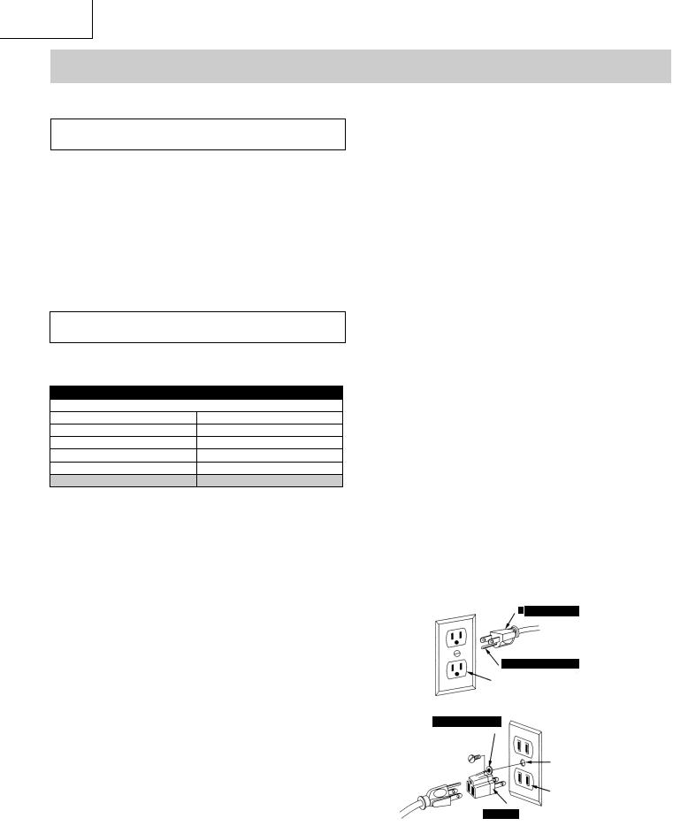
GROUNDING INSTRUCTIONS
IN THE EVENT OF A MALFUNCTION OR BREAKDOWN, grounding provides a path of least resistance for electric current and reduces the risk of electric shock. This saw is equipped with an electric cord that has an equipment grounding conductor and a grounding plug. The plug MUST be plugged into a matching receptacle that is properly installed and grounded in accordance with ALL local codes and ordinances.
DO NOT MODIFY THE PLUG PROVIDED. If it will not
fi t the receptacle, have the proper receptacle installed by a qualifi ed electrician.
 WARNING
Any extension cord must be GROUNDED for safe operation.
MINIMUM GAUGE FOR EXTENSION CORDS (AWG)
(When using 120 volts only)
Ampere Rating |
|
Total length of Cord |
|||
More Than |
Not More Than |
25ft. |
50ft. |
100ft. |
150ft. |
0 |
6 |
18 |
16 |
16 |
14 |
6 |
10 |
18 |
16 |
14 |
12 |
10 |
12 |
16 |
16 |
14 |
12 |
12 |
16 |
14 |
12 |
Not Applicable |
|
GUIDELINES FOR EXTENSION CORDS
Any extension cord used for power tools MUST be grounded (3-wire with two fl at prongs and one round ground prong).
Make sure the extension cord is in good condition. When using an extension cord, make sure you use one heavy enough to carry the current the tool will draw. An undersized cord will cause a drop in line voltage resulting in loss of power and overheating. The table above shows the correct size to use according to extension cord length and nameplate ampere rating. If in doubt, use the next heavier gauge cord. The smaller the gauge number the heavier the cord.
NOTE: The 12 to 16 amp rating is correct for this tool. It is highlighted in the table above.
Be sure your extension cord is properly wired and in good condition. Always replace a damaged extension cord or have it repaired by a qualifi ed person before using it. Protect your extension cords from sharp objects, excessive heat and damp or wet areas.
Before connecting the saw to the extension cord, make sure the saw switch is turned OFF.
IMPROPER CONNECTION of the equipment grounding conductor can result in risk of electric shock. The conductor (wire) with the green insulation (with or without yellow stripes) is the equipment grounding conductor. If repair or replacement of the electric cord or plug is necessary, DO NOT connect the equipment grounding conductor to a live terminal.
CHECK with a qualifi ed electrician or service personnel if you do not completely understand the grounding instructions, or if you are not sure the saw is properly grounded.
Use only 3-wire extension cords that have 3-prong grounding plugs and 3-pole grounding receptacles that accept the saw’s plug. Repair or replace damaged or worn cords immediately.
 d
d  le
le
 sure this is
  ected to a
 n ground.

 ng
ng  tacle
tacle
6
English
ACCESSORIES AND ATTACHMENTS
RECOMMENDED ACCESSORIES |
|
WARNING |
WARNING |
Visit your Hardware Department or see the Power and Hand Tools Catalog to purchase recommended accessories for this power tool.
To avoid the risk of personal injury:
Do not use a dado with a diameter larger than 6”.
Maximum dado width is 1/2”. DO NOT USE WIDER COMBINATIONS.
Do not use molding head set with this saw.
Do not modify this power tool or use accessories not recommended by Store.
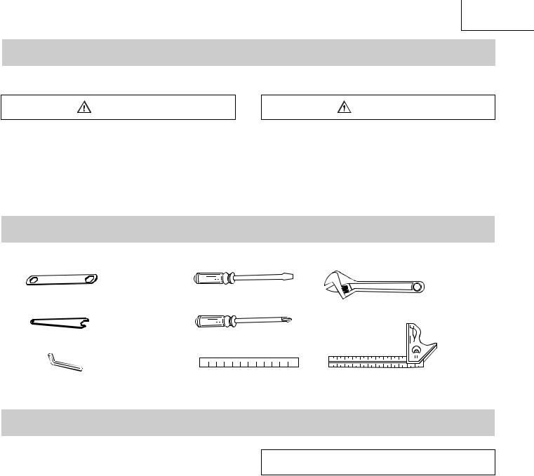
TOOLS NEEDED FOR ASSEMBLY
Supplied |
Not Supplied |
|
Wrench |
Medium Screwdriver |
Adjustable Wrench |
|
|
|
Wrench |
#2 Phillips screwdriver |
|
|
|
|
3 mm Hex Wrench |
Straight Edge |
Combination Square |
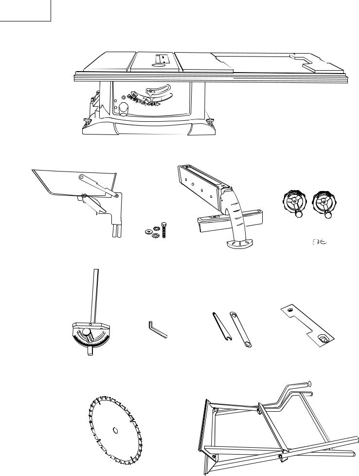
CARTON CONTENTS
UNPACKING AND CHECKING CONTENTS
Separate all parts from packing materials. Check each part with the illustration on the next page and the “Table of Loose Parts” to make certain all items are accounted for, before discarding any packing material.
TABLE OF LOOSE PARTS
ITEM DESCRIPTION QUANTITY
ATable saw assembly
B Blade guard and splitter
CRip fence
D Dado table insert
EMiter gauge
F |
Blade wrench |
2 |
G |
Hand wheel |
2 |
HBlade
Hex wrench
J |
Guard mounting bolt,fl at washer, |
1 each |
|
toothed washer,spring washer |
|
K |
Dome nut |
2 |
 WARNING
If any part is missing or damaged, do not attempt to assemble the table saw, plug in the power cord, or turn the switch ON until the missing or damaged part is obtained and is installed correctly.
STAND
ITEM DESCRIPTION QUANTITY
LStand assembly
NOTE: To make assembly easier, keep contents of box together. Apply a coat of automobile wax to the table.
Wipe all parts thoroughly with a clean dry cloth. This will reduce friction when pushing the workpiece.
7
English
UNPACKING YOUR JOBSITE TABLE SAW
o
5o
1
o |
30 |
o 35o |
|
|
40
45o
A
G
B
J
K
C
F D
E
H
L
8

English
KNOW YOUR JOBSITE TABLE SAW
Blade guard |
Table insert |
Miter gauge |
Rip fence |
|
|
Table |
Side table extension |
|
Hand hold |
Blade tilt scale |
|
Blade tilt pointer |
|
|
Blade bevel lock knob |
|
Blade elevation handwheel |
|
Bevel tilting handwheel |
Overload reset switch |
|
ON/OFF switch with key |
Stand |
|
Rear Of The Table Saw
Rip fence and miter gauge storage
Cord wrap
9

English
GLOSSARY OF TERMS
TABLE SAW TERMS
MITER GAUGE – A guide used for crosscutting operations that slides in the tabletop channels located on either side of the blade. It helps make accurate straight or angle cuts.
RIP FENCE – A guide used for rip cutting that clamps to the tabletop. It allows the workpiece to be straight.
TABLE INSERT – Provides access to the blade arbor for changing blades.
OVERLOAD RESET SWITCH – Resets the thermocouple and provides a way to restart the saw motor if it overheats or overloads.
BLADE BEVEL SCALE – Measures the angle the blade is tilted when set for a bevel cut.
TABLE SCALE – Measures the distance the rip fence is set from the blade, allowing quick setups.
ANTI-KICKBACK PAWLS – Prevents the workpiece from being kicked upward or back toward the front of the table saw by the spinning blade.
SPLITTER – Keeps the workpiece spread apart after being cut, to prevent binding on the blade and workpiece.
BLADE ELEVATION HANDWHEEL – Raises and lowers the blade.
BLADE TILTING HANDWHEEL – Tilts the blade to any angle between 0° to 45° for bevel cuts.
WOODWORKING TERMS
ARBOR – The shaft on which a blade is mounted.
BEVEL CUT – An angle cut made through the face of the workpiece.
COMPOUND CUT – A simultaneous bevel and miter cut
CROSSCUT – A cut made across the width of the workpiece.
FREEHAND – Performing a cut without using a fence
(guide), hold down or other proper device to prevent the workpiece from twisting during the cutting operation.
GUM – A sticky sap from wood products.
HEEL – Misalignment of the blade.
KERF – The amount of material removed by a blade cut
MITER CUT – An angle cut made across the width of the workpiece.
RESIN – A sticky sap that has hardened.
REVOLUTIONS PER MINUTE (RPM) – The number of turns completed by a spinning object in one minute.
SAW BLADE PATH – The area of the workpiece or table top directly in line with the travel of the blade or the part of the workpiece that will be cut.
SET – The distance between two saw blade tips, bent outward in opposite directions to each other. The further apart the tips are, the greater the set.
WORKPIECE – The item being cut. The surfaces of a workpiece are commonly referred to as faces, ends and edges.
Leading Edge |
Saw Blade Path |
|
Kerf
Surface
Trailing Edge
Workpiece
10
English
ASSEMBLY AND ADJUSTMENTS
ESTIMATED ASSEMSLY TIME 25~40 MINUTES ASSEMBLE THE TABLE SAW TO THE STAND (FIG. A)
.Unfold the leg sets and push down in place.
2.Place the stand on a level surface and adjust the front-right adjustable foot, so all legs are contacting the fl oor and are at similar angles on the fl oor.
3. Match the holes of the stand to the holes on the bottom fl ange of the saw base.
4.Fasten the saw to the stand using the four handles
(1) then tighten securely .
5.Position the saw on a clean, level surface.
Fig. A
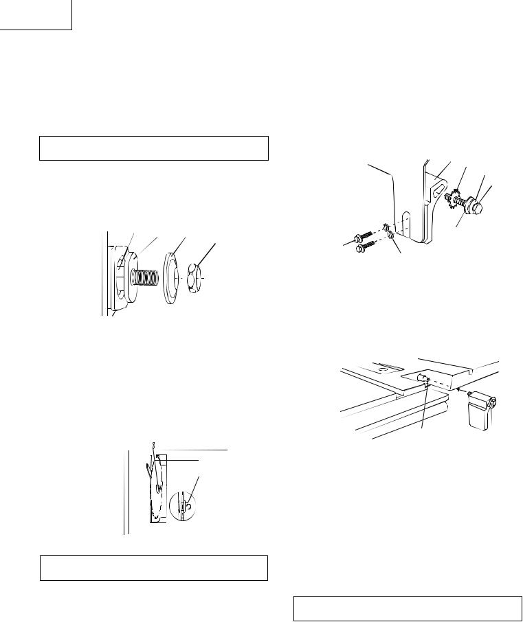
BLADE RAISING HANDWHEEL (FIG. B)
1.Attach the up ~ down handwheel (1) to the elevation rod (2) at the front of the saw. Make sure the slots (3) in the hub of the handwheel (1) engage with the pins (4).
2.Attach and tighten the dome nut (5-Fig.C)
Fig. B
2 4
3
BLADE TILTING HANDWHEEL (FIG. C)
1.Attach the bevel 0° ~ 45° handwheel (6) to the blade tilting rod on the right side of the saw in the same manner as above.
2.Attach and tighten the handwheel dome nut (5).
Fig. C
5


 6
6
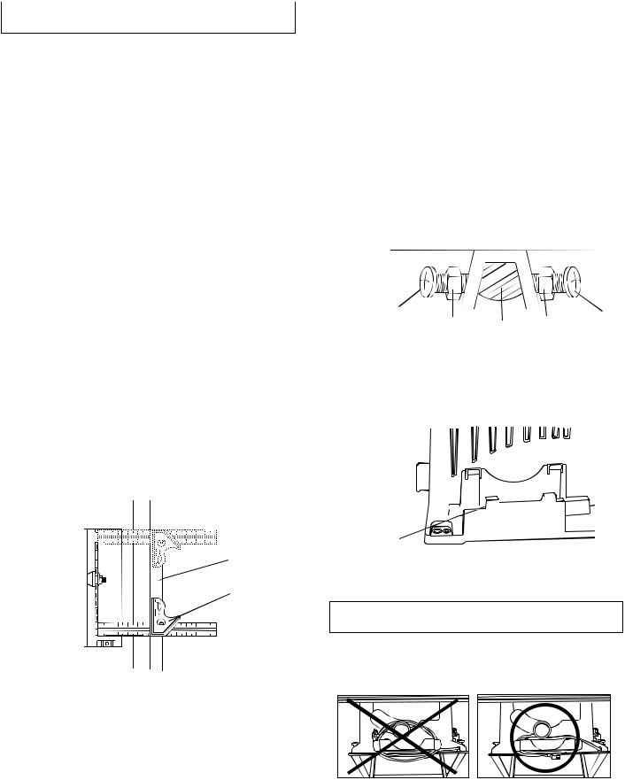
INSTALLING AND REMOVING THE BLADE (FIG. D)
 WARNING
To avoid injury from an accidental start, make sure the switch is in the OFF position and the plug is disconnected from the power source outlet.
To avoid serious injury, the rear of the table insert must be level with the table. If the rear of the insert is not level with the table, adjust the screw (3) in or out until the rear of the insert is level to or slightly above the table. To raise the insert, turn the screw counterclockwise, to lower the insert, turn the screw clockwise. NOTE: A rubber adjusting spacer is provided under rear of insert for this purpose.
1.Remove the table insert (1) by removing the two screws (2, 3). Be careful not to lose the rubber washer that is on the back screw (3) beneath the table insert. (Fig. D)
Fig. D
3
 2
2
2.Raise the blade arbor (4-Fig. E) to the maximum height by turning the blade raising handwheel counterclockwise.
3.Place the open-end wrench (8) jaws on the fl ats of the saw arbor to keep the arbor from turning (Fig. F) and place the box-end wrench (9) on the arbor nut (5), and turn counterclockwise.
11
English
4.Remove the arbor nut (5) and outer fl ange (6). (Fig. E)
5.Install the saw blade onto the arbor with the blade teeth pointing toward the front of the saw
6.Install the fl ange (6) against the blade and thread the arbor nut (5) as far as possible by hand. Ensure that the blade is fl ush againstthe inner side of the blade fl ange.
 WARNING
To avoid possible injury and damage to the workpiece, be sure to install the blade with the teeth pointing toward the front of table in the direction of the rotation arrow on the blade guard.
Fig. E |
4 |
7 |
6 |
5
7.To tighten the arbor nut (5), place the open-end wrench (8) on the fl ats of the saw arbor to keep the arbor from turning. (Fig. F)
8.Place the box-end wrench (9) on the arbor nut (5), and turn clockwise (to the rear of the table).
9.Replace the blade insert in the table recess, insert the screws through the front and rear hole and tighten remembering the rubber washer under the rear of the insert and leveling the rear of the insert to the table.
Fig. F |
9 |
8
 5
5
 WARNING
To avoid injury from a thrown workpiece, blade parts, or blade contact, never operate saw without the proper insert in place. Use the original installed insert for all throught sawing operations except dado cuts. A special dado insert plate must be installed when using a dado blade.
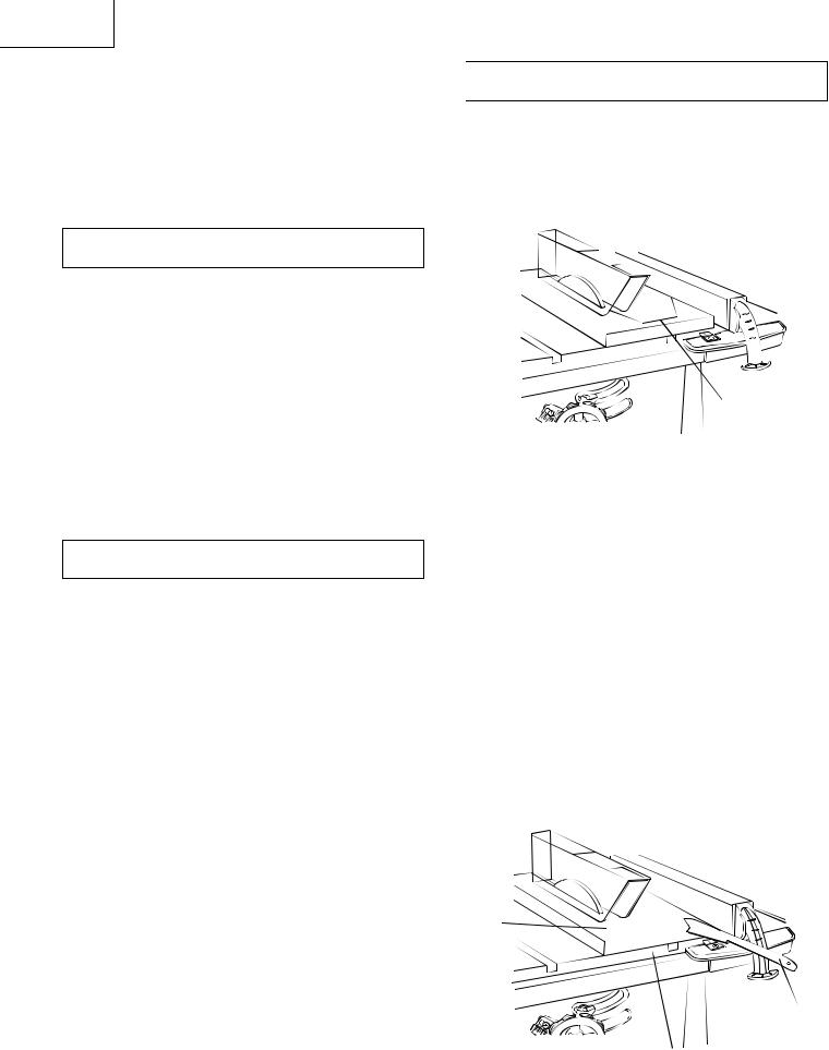
BLADE GUARD ASSEMBLY (FIG. G, H, I )
1.Set the blade to maximum height and the tilt to zero degrees on the bevel scale with the hand wheels. Lock the blade bevel lock knob.
2.Place the spring washer (2), fl at washer (3), external tooth lock washer (4) onto the blade guard mounting bolt (1-Fig. G).
3.Insert bolt and washer assembly through splitter bracket (5).
Fig. G 5 4
2
Blade guard splitter 
3
12
1
4.Install the blade guard splitter & bracket assembly into the rear of the saw table. Thread the bolt (1) into the internally threaded pivot rod (7-Fig. H) until snug.
NOTE: The blade guard and splitter is removed from the illustration for clarity.
Fig. H
7
6.Lift blade guard arm (8) up and using a straight edge, align the blade guard splitter (9) with the saw blade (10). (Fig. I)
7.Shift the splitter bracket assembly to right or left until parallel alignment to the blade is achieved.
8.When the splitter is properly aligned with the saw blade, tighten the bolt securely.
NOTE: The splitter bracket must always be correctly aligned so the cut workpiece will pass on either side without binding or twisting.
 WARNING
See Fig. G fl at washers (11) must be under bolts (12). NOTE: Be sure to tighten nuts very tight and periodically check tightness.
12

 WARNING
Improper splitter alignment can cause “kickback” and serious injury
Fig.
Anti-kickback Pawl |
8 |
10 |
9
Straight edge
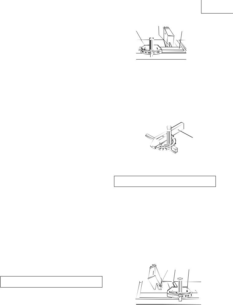
ADJUSTING THE 90°(00) AND 45° POSITIVE STOPS (FIG. J, K, L)
Your saw has positive stops that will quickly position the saw blade at 90°(00) and 450 to the table. Make adjustments only if necessary.
90°(00) Stop
1.Disconnect the saw from the power source.
2.Turn the blade elevation handwheel and raise the blade to the maximum elevation.
3.Loosen the blade bevel lock knob (1) and move the blade to the maximum vertical position, then tighten the lock knob (1).
4.Place a combination square on the table and against the blade (2) to determine if the blade is 90°(00) to the table. (Fig. K)
5.If the blade is not 90°(00) to the table, loosen the two set screws (4), located on the collar (5) underneath the table saw (Fig. L) with the hex key, and back off the collar.
6.Loosen the bevel lock knob, turn the blade tilting handwheel to move the blade until it is 90°(00) to the table and tighten the bevel lock knob.
7.Adjust the collar (5) so it contacts the bracket (3) when the blade is 90°(00) to the table. Tighten the two set screws (4). (Fig.L)
Fig. J
English
Fig. K
900 (00) |
450 |
2
45° Stop
1.With the blade in the upright 90°(00) position, loosen the bevel lock knob and move the blade to the maximum bevel angle.
2.Place the combination square on the table as shown in Fig. K to check if the blade is 45° to the table.
3.If the blade is not 45° to the table, loosen the two set screws (4), located on the collar (5) nuderneath the table saw, with the hex key, and back off the collar.
(Fig. L)
4.Loosen the bevel lock knob, turn the blade tilting handwheel to move the blade until it is 45° to the table and tighten the blade bevel lock knob.
5.Adjust the collar (5) so it contacts the bracket (3) when the blade is 45° to the table. Tighten the two set screws
BLADE TILT POINTER
1.When the blade is positioned at 90°(00), adjust the blade tilt pointer to read 0° on the scale.
2.Loosen the mounting screw, position pointer over 0° and tighten the screw.
NOTE: Make a trial cut on scrap wood before making critical cuts. Measure for exactness.
Fig. L
4 |
3 |
|
|
|
|
|
|
450 |
5 |
3 |
|
|
4 |
|
|
|
900(00)
5
13
BLADE PARALLEL TO THE MITER GAUGE GROOVE (FIG. M, N)
 WARNING
To avoid injury from an accidental start, make sure the switch is in the OFF position and the plug is disconnected from the power source outlet.
This adjustment was made at the factory, but it should be rechecked and adjusted if necessary.
This adjustment must be correct or kickback could result in a serious injury and accurate cuts can not be made.
1.Remove the safety switch key and unplug the saw.
2.Remove the blade guard for this procedure but reinstall and realign after adjustment.
3.Raise the blade to the heighest position and set at the 0° angle (900 straight up)
4.Select and mark with a felt tip marker, a blade tooth having a “right set” and rotate the blade so the marked tooth is 1/2 in. Above the table.
5.Place the combination square base (1) into the right side miter gauge groove (2). (Fig.M)
6.Adjust the ruler so it touches the front marked tooth and lock ruler so it holds its position in the square assembly.
7.Rotate the blade to the rear of the saw bringing the marked tooth approximately ½” above the blade.
8. Carefully slide the combination square to the rear until the ruler touches the marked tooth.
9.If the ruler touches the marked tooth at the front and rear position, no adjustment is needed at this time. If not or the base of the miter gauge groove, perform adjustment procedure described in next section.
Fig. M
2
counterclockwise, then adjust the right side screw(3) clockwise.
2.Remeasure, as described in steps 4 to 9 in the prior section
3.When alignment is achieved, turn the left screw (2) nutil it touches the pivot rod (4) then tighten both nuts (1).
If the blade is partial to left side:
4.Loosen the two nuts (1) and tighten the left screw (3) counterclockwise, then adjust the left side screw (2) clockwise.
5.Remeasure, as described in steps 4 to 9 in the prior section.
6.When alignment is achievde, turn the right screw (3) nutil it touches the pivot rod (4) then tighten both nuts (1).
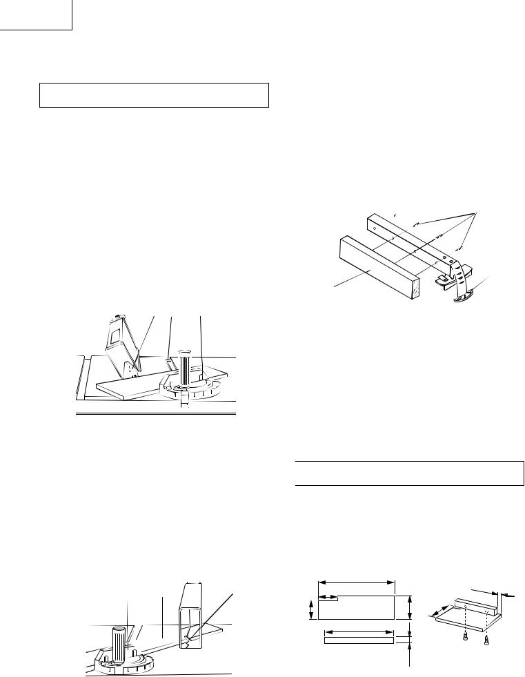
Fig. N
2
3
4
STORAGE (FIG. O, P)
Rip fence and miter gauge (Fig. O)
Storage brackets for the rip fence (2) and miter gauge
(3)are located on the left side of the saw housing.
Fig. O
2 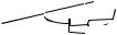

3
Cord wrap (Fig. O-1)
 WARNING
Do not wrap the cord around the dust port.
Fig. O-1
Additional Blade Adjustments (Fig. N)
NOTE: The adjusting nuts are 8 mm. The adjusting mechanism is located above the blade
height adjusting hand wheel nuder the tabletop. If the front and rear measurments are not the same.
If the blade is partial to right side:
1. Loosen the two nuts (1) and turn the left screw (2)
- 14 -
Blade (Fig. P)
1.Loosen and remove the knob (1) on the right side of the saw housing.
2.Place extra blades onto the arbor. Replace the knob and tighten.
Fig. P
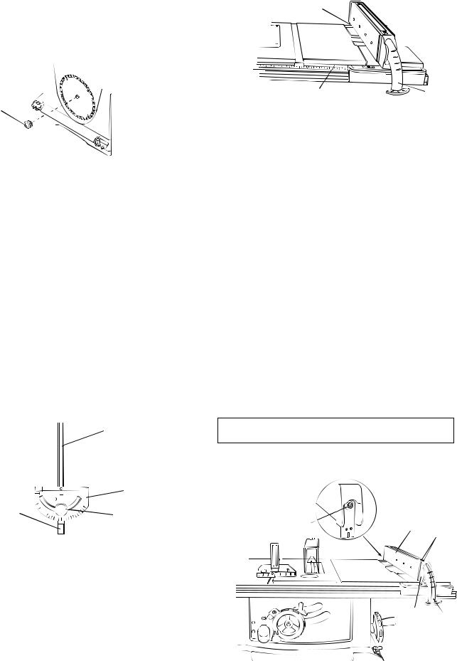
MITER GAUGE ADJUSTMENT (FIG. Q)
1.Make sure that the miter gauge bar (1) will slide freely through the table top grooves.
2.Loosen the lock knob handle (2) and turn the gauge body (3) to set the pointer (4) at 0º on the scale
3.Make a 90 cut in a scrap piece of wood. Check the cut to see if it is 90 . If not, loosen the lock knob handle (2) and move the miter gauge body until it is square to the miter gauge bar by using a combination square.
MITER GAUGE OPERATION (FIG. Q)
The miter gauge is accurately constructed with index stops at 0 , 15 , 30 , 45 , 60 both right and left side.
The operate the miter gauge, simply loosen the lock handle (2) and move the body of the miter gauge to the desired angle. The miter gauge body will stop at 0 , 15 30 , 45 , 60 both right and left side.
Fig. Q
Fig. R
2
3
RIP FENCE ADJUSTMENT (FIG. S)
1.The fence (1) is moved by lifting up on the handle (2) and sliding the fence to the desired location. Pushing down on the handle locks the fence in position.
2.Position the fence on the right side of the table, and along one edge of the miter gauge grooves.
3.Lock the fence handle. The fence should be parallel with the miter gauge groove.
4.If adjustment is needed to make the fence parallel to the groove, do the following:
•Loosen the two screws (3) and lift up on the handle (2).
•Hold the fence bracket (4) fi rmly against the front of the saw table. Move the far end of the fence until it is parallel with the miter gauge groove.
•Tighten both screws and push the handle to lock.
5.If fence is loose when the handle is in the locked
(downward) position, do the following:
•Move the handle (2) upward and turn the adjusting nut (5) clockwise until the rear clamp is snug. Do not turn the adjusting screw more than 1/4 turn at a time.
•Over-tightening the adjusting screw will cause the fence to come out of alignment.
4
60  45
45
 30
30
15
15
60
45
30
 WARNING
Failure to properly align the fence can cause “ kickback” and serious injury could occur.
3 |
Fig. S |
2
5
3
RIP FENCE (FIG. R)
1.Lift upward on the rip fence handle (1) so that the holding clamp (2) is fully extended.
2.Place the rip fence on the saw table and engage the holding clamp (2) to the table rear. Lower the front end onto the front rail (3).
3.Push down on the fence handle (1) to lock.
- 15 -
4
2

English
RIP FENCE INDICATOR (FIG. T)
NOTE: The rip fence indicator points to the scale on the front of the table saw. Measurement shown by the indicator will provide the user with accuracy up to 1/16 of an inch. Measurement shown is the distance from the blade to the side of the fence closest to the blade.
1.To check the accuracy, measure the actual distance
(1)to the side of the rip fence. If there is a difference between the measurement and the indicator, adjust the indicator as shown next.
2.Loosen the indicator screw (2). Slide the indicator to the correct measurement position on the scale, then retighten the screw (2).
Fig. T
2
TABLE EXTENSION SCALE POINTER (FIG. T-1)
The table extension scale pointer (1) should be at 13.5 inches on the scale when the extension is in the closed position. If not, loosen the holding screw (2), position the pointer over 13.5 inches and re-tighten the screw.
Fig. T-1
2
ADJUSTING THE CUTTING LINE INDICATOR (FIG. U)
1.Take off the cover (1) by loosening screws (2).
2.Adjust the pointer (3) to align to the blade.
3.Mount the cover on the table to fi x the pointer.
NOTE: The pointer was set up to align to the right side of the blade when packing.
Fig. U
3


 2
2
ADJUSTING CAM LOCKING LEVER (FIG. V)
If the extension table moves when it is open and locked, then the cam locking lever (1) may be loose and need adjustment, therefore, adjustment to the cam locking lever is necessary. To adjust the locking lever tension, turn the bar (2) with a 10 mm wrench until it is tightened, but do not over tighten.
Fig. V
2
16
English
OPERATION
BASIC SAW OPERATIONS
RAISE THE BLADE (FIG. W)
To raise or lower the blade, turn the blade elevation handwheel (1) to the desired blade height, and then tighten the bevel lock handle (2) to maintain the desired blade angle.
Fig. W |
2 |
3
TILTING THE BLADE (FIG. W)
1.To tilt the saw blade for bevel cutting, loosen the bevel lock knob (2) and turn the tilting handwheel (3).
2.Tighten the bevel lock knob (2) to secure.
ON/OFF SWITCH (FIG. X)
OVERLOAD PROTECTION (FIG. X)
This saw has an overload relay button (3) that resets the motor after it shuts off due to overloading or low voltage. If the motor stops during operation, turn the ON / OFF switch to the OFF position and unplug the saw.
Wait about fi ve minutes for the motor to cool, Plug in the saw, push in the reset button (3) and turn the switch to the ON position.
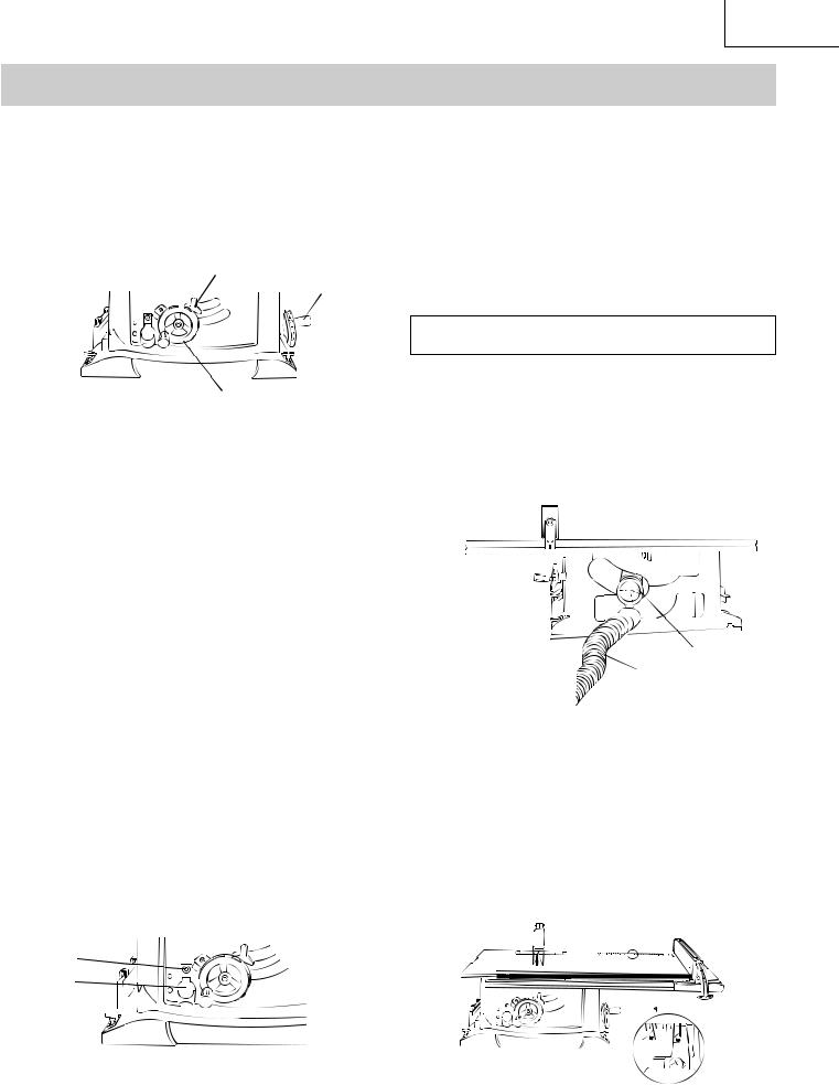
USING THE DUST CHUTE (FIG. Y)
 WARNING
To prevent fi re hazard, clean and remove sawdust from under the saw frequently.
To prevent sawdust buildup inside the saw housing, attach a vacuum hose (1) to the dust chute (2) at the rear of the table saw. DO NOT operate the saw with the hose in place unless the vacuum is turned on.
Fig. Y
The ON / OFF switch has a removable safety key. With the key removed from the switch, unauthorized and hazardous use by children and others is minimized and the saw will not turn on.
1.To turn the saw ON, insert key (1) into the slot in the switch (2). Move the switch upward to the ON position.
2.To turn the saw OFF, move the switch downward.
3.To lock the switch in the OFF position, grasp the sides (or yellow part) of the switch toggle (1), and pull it out.
4.With the switch key removed, the switch will not operate
5.If the switch key is removed while the saw is running, it can be turned OFF but cannot be restarted without re-inserting the switch key (1).
Fig. X
3
2

2
USING THE TABLE EXTENSION (FIG. Z)
NOTE: Use scale on front rail for rip cuts up to 13.5”. For rip cuts greater than 13.5” set the lock the fence on the
13.5” mark. Unlock the extension table, and slide the table with the fence to the desired dimension using the scale on rear rail.
Release cam locking lever.
1.Slide the table extension to the desired measurement and then tighten the cam locking lever.
Fig. Z
17
English
CUTTING OPERATIONS
There are two basic types of cuts: ripping and crosscutting. Ripping is cutting along the length and the grain of the workpiece. Crosscutting is cutting either across the width or across the grain of the workpiece. Neither ripping nor crosscutting may be done safely freehand. Ripping requires the use of the rip fence, and crosscutting requires the miter gauge.
 WARNING
Before using the saw each and every time, check the following:
1.The blade is tightened to the arbor.
2.The bevel angle lock knob is tight.
3.If ripping, the fence is locked into position & is parallel to the miter gauge groove.
4.The blade guard is in place and working properly.
5.Safety glasses are being worn.
The failure to adhere to these common safety rules, and those printed in the front of this manual, can greatly increase the likelihood of injury.
RIPPING (FIG. AA, BB)
 WARNING
To prevent serious injury:
Never use a miter gauge when ripping.
•Never use more than one rip fence during a single cut.
Do not allow familiarity or frequent use of your table saw to cause careless mistakes. Remember that even a careless fraction of a second is enough to cause a severe injury.
Keep both hands away from the blade and clear from the path of the blade.
The workpiece must have a straight edge against the fence and must not be warped, twisted, or bowed when ripping.
1.Remove the miter gauge and store it in the “storage” compartment in the base of the saw.
2.Secure the rip fence to the table.
3.Raise the blade so it is about 1/8 in higher than the top of the workpiece.
4.Place the workpiece fl at on the table and against the fence. Keep the workpiece away from the blade.
5.Turn the saw ON and wait for the blade to come to full speed.
6.Slowly feed the workpiece into the blade by pushing forward only on the workpiece section (1) that will pass between the blade and the fence. (Fig. AA)
 WARNING
AVOID KICKBACK by pushing forward on the section of the workpiece that passes between the blade and the fence. Never perform any freehand operations.
Fig. AA
NOTE: Always use a push stick. When width of the rip is narrower than 2 in the push stick cannot be used because the guard will interfere…therefore, use the auxiliary fence so the push stick can be used as shown on page 24.
7.Keep your thumbs off the table top. When both of your thumbs touch the front edge of the table (2),
finish the cut with a push stick. To make an additional push stick, use the pattern on page 24.
8.The push stick (3) should always be used. (Fig. BB)
9.Continue pushing the workpiece with the push stick
(3)until it passes through the blade guard and clears
the rear of the table.
10.Never pull the piece back when the blade is turning.
Turn the switch OFF. When the blade completely stops, you can then remove the workpiece.
Fig. BB
3
2
18
BEVEL RIPPING
This cut is the same as ripping except the blade bevel angle is set to an angle other than 0
RIPPING SMALL PIECES
To avoid injury from the blade contact, never make cuts narrower than 1/2 in wide.
1.It is unsafe to rip small pieces. Instead, rip a larger piece to obtain the size of the desired piece.
2.When a small width is to be ripped and your hand cannot safely pass between the blade and the rip fence, use one or more push sticks to move the workpiece. Always use a push stick during ripping operations.
CROSSCUTTING (FIG. CC)
To prevent serious injury:
Do not allow familiarity or frequent use of your table saw to cause careless mistakes. Remember that even a careless fraction of a second is enough to cause a severe injury.
Keep both hands away from the blade and the path of the blade.
Never attempt to pull the workpiece backwards during a cutting operation. This will cause kickback and serious injury to the user can occur.
1.Remove the rip fence and place the miter gauge in a miter gauge groove on the table.
2.Adjust the blade height so it is 1/8 in. higher than the top of the workpiece.
3.Hold the workpiece fi rmly against the miter gauge with the blade path in line with the desired cut location. Move the workpiece to 1in. distance from the blade.
4.Start the saw and wait for the blade (1) to come up to full speed. Never stand directly inline of the saw blade path, always stand to the side of the blade that you are cutting on.
5.Keep the workpiece (2) against the face of the miter gauge (3) and fl at against the table. Then slowly push the workpiece through the blade.
6.Do not try to pull the workpiece back with the blade turning. Turn the switch OFF, and carefully slide the workpiece out when the blade is completely stopped.
 WARNING
Always position the larger surface of the workpiece on the table when crosscutting and/or bevel crosscutting to avoid instability.
English
Fig. CC
3 |
2 |
USING WOOD FACING ON THE MITER GAUGE
(Fig. DD)
Slots are provided in the miter gauge for attaching an auxiliary facing (1) to make it easier to cut very long or short pieces. Select a suitable piece of smooth wood, drill two holes through it and attach it to the miter gauge with screws. Make sure the facing does not interfere with the proper operation of the sawblade guard. When cutting long workpieces, you can make a simple outfeed support by clamping a piece of plywood to a sawhorse.
Fig. DD
BEVEL CROSSCUTTING (FIG. EE)
This cutting operation is the same as crosscutting except the blade is at bevel angle other than 0°.
 WARNING
Always work to the right side of the blade during this type of cut. The miter gauge (1) must be in the right side groove (2) because the bevel angle may cause the blade guard to interfere with the cut if used on the left side groove.
1.Adjust the blade (3) to the desired angle, and tighten the blade bevel lock knob.
2.Tighten miter lock handle at 90°.
3.Hold workpiece fi rmly against the face of the miter gauge (1) throughout the cutting operation.
NOTE: When tilting the blade to 45°, the miter gauge handle will hit the blade guard.
Fig. EE |
3 |
2 |
|
19
English
COMPOUND MITER CROSSCUTTING (FIG. FF)
This sawing operation is combining a miter angle with a bevel angle.
 WARNING
Always work to the right side of the blade during this type of cut. The miter gauge (3) must be in the right side groove because the bevel angle may cause the blade guard to interfere with the cut if used on the left side groove.
When tilting the workpiece to 45° and push it toward the blade, the blade guard may hit the blade. To avoid injury, stop the work at that time.
1.Set the miter gauge (3) to the desired angle.
2.Place the miter gauge (3) in the right side groove (2) of the table.
3.Set the blade (1) bevel to the desired bevel angle and tighten the blade bevel lock knob.
4.Hold workpiece fi rmly against the face of the miter gauge (3) throughout the cutting operation.
2 3
Fig. FF
MITER CUTS (FIG. GG)
This sawing operation is the same as crosscutting except the miter gauge is locked at an angle other than 90°.
1.Set the blade (1) to 0° bevel angle and tighten the blade bevel lock knob.
2.Set the miter gauge (3) at the desired miter angle and lock in position by tightening the miter gauge locking handle.
3.Hold the workpiece (2) fi rmly against the face of the miter gauge throughout the cutting operation.
Fig. GG
32
USING WOOD FACING ON THE RIP FENCE (FIG. HH)
When performing some special cutting operations, add a wood facing (1) to either side of the rip fence (2).
1.Use a smooth & straight 3/4 in thick wood board
(1) that is as long as the rip fence.
2.Attach the wood facing to the fence with wood screws (3) through the holes in the fence. A wood fence should be used when ripping material such as thin paneling to prevent the material from catching between the bottom of the fence and the table.
Fig. HH

 3
3
2
AUXILIARY FENCE (FIG. II)
Making the base:
Start with a piece of 3/8 in plywood at least 5-1/2 in wide or wider and 30 in long or longer.
Cut the piece to shape and size shown:
Making the side:
Start with a piece of 3/4 in plywood at least 2-3/8 in wide or wider and 27 in long or longer
Cut the piece to shape and size shown:
Putting it together:
Put the pieces together, as shown:
 WARNING
Make sure the screw heads do not stick out from the bottom of the base, they must be fl ush or recessed. The bottom must be fl at and smooth enough to rest on the saw table without rocking.
|
Fig. II |
|
|
|
|
30” |
|
|
1-1/4” |
|
2-5/8” |
|
|
|
1/2”-3 |
1/2”-5 |
- |
|
|
|
||||
|
|
|||
|
3/8” Thick plywood base |
|
43/4” |
|
|
27” |
|
|
|
|
3/4” Thick plywood side |
|
|
|
|
|
2-3/8” |
|
|
20
English
Attach auxiliary fence to rip fence with two “C” |
Fig. KK |
clamps. (Fig. JJ) |
|
Fig. JJ |
2 |
|
3
DADO CUTS (FIG. KK)
1.The dado blade insert is included with this saw. Remove the saw blade, original table inser and blade guard. Install the dado and dado blade insert.
2.Instruction for operating the dado is packed with the separately purchased dado set.
3.The arbor (1) on this saw restricts the maximum width of the cut to 1/2 in.
4.When making full 1/2 in dado cuts, it is not necessary to install the outside fl ange (2) before screwing on the arbor nut (3). Make sure that the arbor nut (3) is tight, and that at least one thread of the arbor sticks out past the nut.
5.Do not exceed 6 in diameter dadoes and keep the width 1/2 in or less. It will be necessary to remove the blade guard and splitter when using a dado blade. Always use caution when operating a dado blade.
6.Use only the correct number of round outside blades and inside chippers as shown in the dado set’s instruction manual. Blade or chipper must not exceed
1/2 in.
7.Check saw to ensure that the dado will not strike the housing, insert, or motor when in operation.
 WARNING
For your own safety, always replace the blade, blade guard assembly, and blade insert when you are
fi nished with the dado operation.
21
English
MAINTENANCE
MAINTAINING YOUR TABLE SAW
GENERAL MAINTENANCE
 WARNING
For your own safety, turn the switch OFF and remove the switch key. Remove the plug from the power source outlet before maintaining or lubricating your saw.
1.Clean out all sawdust that has accumulated inside the saw cabinet and the motor.
2.Polish the saw table with an automotive wax to keep it clean and to make it easier to slide the workpiece.
3.Clean cutting blades with pitch and gum remover.
4.A worn, cut, or damaged power cord should be replaced immediately.
 WARNING
All electrical or mechanical repairs should be attempted only by a trained repair technician.
Contact the nearest Hitachi Authorized Service Center for service. Use only identical replacement parts. Any other parts may create a hazard.
5.Use liquid dish washing detergent and water to clean all plastic parts.
NOTE: Certain cleaning chemicals can damage plastic parts.
6.Avoid use of cleaning chemicals or solvents, ammonia and household detergents containing ammonia.
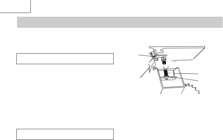
BLADE RAISING AND TILTING MECHANISM (FIG. LL)
After each fi ve hours of operation, the blade raising mechanism and tilting mechanism should be checked for looseness, binding, or other abnormalities. With the saw dis-connected from the power source, turn the saw upside down and alternately pull upward and downward on the motor unit. Observe any movement of the motor mounting mechanism. Looseness or play in the blade raising screw (1) should be adjusted as follows:
1.Using a wrench, loosen nut (2).
2.Adjust nut (3) until it is fi nger-tight against the bracket (4), and then back off the nut (3) 1/6 turn.
3.Tighten nut (2) with the wrench, while holding nut (3) in place. Maximum allowable play of screw rod (1) is 0.16 in. (4 mm).
Fig. LL
3


 2
2
4 |
5 |
|
Place a small amount of dry lubricant on bevel gear (2). Screws rod (1) must be kept clean and free of sawdust, gum, pitch, and other contaminants for smooth operation.
If excessive looseness is observed in any parts of the blade raising mechanism or tilting mechanism, contact
Hitachi Authorized Service Center immediately.
LUBRICATION
All motor bearings are permanently lubricated at the factory and require no additional lubrication.
On all mechanical parts of your table saw where a pivot or threaded rod are present, lubricate using graphite or silicone. These dry lubricants will not hold sawdust as would oil or grease.
22
 Loading...