


Hitachi CG 22EASS, CG 22EASSL, CG 27EASS, CG 24EASS, CG 22EADSL User Manual
...Grass Trimmer/Brush Cutter
Model CG 22EAS(SL)/CG 22EAS(S) CG 22EAD(SL)/CG 22EAB(SL) CG 24EAS(SL)/CG 24EAS(S) CG 27EAS(SL)/CG 27EAS(S)
Handling instructions
CG22EAS (SL)
Note:
Before using this machine, carefully read through these HANDLING INSTRUCTIONS to ensure e cient, safe operation. It is recommended that these INSTRUCTIONS be kept readily available as an important reference when using this machine.
MEANINGS OF SYMBOLS
NOTE: Some units do not carry them.
Symbols WARNING
The following show symbols used for the machine. Be sure that you understand their meaning before use.
|
|
|
|
|
It is important that you read, fully |
|
|
|
|
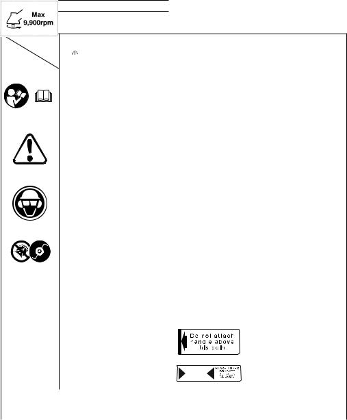
Shows maximum shaft speed. Do not |
|
|
|
|
|
|
|
|
|
||
|
|
|
|
|
understand and observe the following |
|
|
|
|
|
|
|
|
|
|
safety precautions and warnings. |
|
|
|
|
use the cutting attachment whose |
|
|
|
|
|
Careless or improper use of the unit may |
|
|
|
|
max rpm is below the shaft rpm. |
|
|
|
|
|
cause serious or fatal injury. |
|
|
|
|
|
|
|
|
|
|
|
|
|
|
|
|
|
|
|
|
|
Read, understand and follow all warnings |
|
|
|
Gloves should be worn when |
|
|
|
|
|
|
|
|
|
|||
|
|
|
|
|
and instructions in this manual and on |
|
|
|
|
necessary, e.g., when assembling |
|
|
|
|
|
the unit. |
|
|
|
|
cutting equipment. |
|
|
|
|
|
|
|
|
|
|
|
|
|
|
|
|
|
|
|
|
|
|
|
|
|
|
|
Always wear eye, head and ear protectors |
|
|
|
Use anti-slip and sturdy footwear. |
|
|
|
|
|
|
|
|
|
|||
|
|
|
|
|
when using this unit. |
|
|
|
|
|
|
|
|
|
|
|
|
|
|
|
|
|
|
|
|
|
|
|
|
|
|
|
|
|
|
|
|
|
|
|
|
|
|
|
|
|
|
|
Do not use metal/rigid blades when this |
|
|
|
|
Blade thrust may occur when the |
|
|
|
|
|
|
|
|
|
||
|
|
|
|
|
|
|
|
|
spinning blade contacts a solid object |
|
|
|
|
|
|
sign is shown on the unit. |
|
|
|
|
in the critical area. A dangerous |
|
|
|
|
|
|
|
|
|
|
reaction may occur causing the |
|
|
|
|
|
|
|
|
|
|
entire unit and operator to be thrust |
|
|
|
|
|
|
|
|
|
|
|
|
|
|
|
|
|
|
|
|
|
violently. This reaction is called blade |
|
|
|
|
|
|
|
|
|
|
thrust. As a result, the operator may |
|
|
|
|
|
Keep all children, bystanders and helpers |
|
|
|
lose control of the unit which may |
|
|
|
|
|
|
15 m away from the unit. If anyone |
|
|
|
|
cause serious or fatal injury. Blade |
|
|
|
|
|
approaches you, stop the engine and |
|
|
|
|
thrust is more likely to occur in areas |
|
|
|
|
|
cutting attachment immediately. |
|
|
|
|
where it is di cult to see the material |
|
|
|
|
|
|
|
|
|
|
to be cut. |
|
|
|
|
|
|
|
|
|
|
|
|
|
|
|
|
|
|
|
|
|
Indicate handle location. Do not |
|
|
|
|
|
Be careful of thrown objects. |
|
|
|
|
attach handle above this point. |
|
|
|
|
|
|
|
|
|
|
|
|
|
|
|
|
|
|
|
|
Indicates blade guard location for a |
|
|
|
|
|
|
|
|
|
|
|
|
|
|
|
|
|
|
|
|
|
|
trimmer head or semi-auto cutting |
|
|
|
|
|
|
|
|
|
|
head. |
|
Before using your machine |
|
|
|
|
|
||||
|
• Read the manual carefully. |
|
|
|
|
|
||||
|
• Check that the cutting equipment is correctly assembled and adjusted. |
|
||||||||
|
• Start the unit and check the carburetor adjustment. See “MAINTENANCE”. |
|
||||||||
Contents |
|
3 |
|
|
|
|
||||
WHAT IS WHAT ................................................................................. |
|
|
|
|
|
|||||
WARNINGS AND SAFETY INSTRUCTIONS ................................... |
4 |
|
|
|
|
|||||
SPECIFICATIONS ............................................................................. |
|
5 |
|
|
|
|
||||
ASSEMBLY PROCEDURES.............................................................. |
5 |
|
|
|
|
|||||
OPERATING PROCEDURES............................................................ |
8 |
|
|
|
|
|||||
MAINTENANCE............................................................................... |
10 |
|
|
|
|
|||||
2
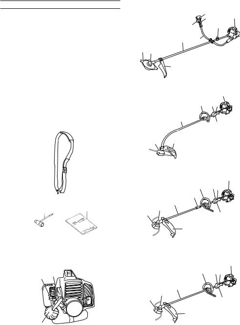
WHAT IS WHAT
Since this manual covers several models, there may be some di erence between pictures and your unit. Use the instructions that apply to your unit.
1.Fuel cap
2.Throttle trigger
3.Starter handle
4.Blade guard
5.Cutting attachment
6.Drive shaft tube
7.Handle
8.Suspension eyelet
9.Ignition switch
10.Harness
11.Throttle trigger lockout
12.Choke lever
13.Engine
14.Angle transmission
15.Joint case
16.Combi box spanner
17.Handling instructions
 10
10
16 |
17 |
12 3
1
|
|
|
9 |
|
|
13 |
|
|
|
11 |
|
|
|
|
|
|
2 |
|
|
8 |
|
|
6 |
7 |
|
|
|
|
|
|
|
|
|
|
5 |
14 |
|
|
|
|
|
|
|
4 |
|
|
CG22EAS (S) |
|
|
|
|
|
|
CG24EAS (S) |
|
|
|
|
|
|
CG27EAS (S) |
|
|
|
|
|
|
|
13 |
|
|
|
7 |
9 |
11 |
|
|
|
6 |
|
|
2 |
|
|
|
|
|
|
||
|
5 |
4 |
|
|
|
|
|
|
|
|
|
CG22EAB (SL) |
|
|
|
|
|
|
|
13 |
|
|
|
7 |
9 11 |
||
|
|
|
15 |
|
|
|
|
|
6 |
|
|
|
|
|
5 |
14 |
|
|
|
2 |
|
|
|
|
|
||
|
|
4 |
|
|
CG22EAD (SL) |
|
|
|
|
|
|
|
13 |
|
|
|
7 |
|
9 |
11 |
|
|
6 |
|
|
|
|
|
5 |
14 |
|
|
|
2 |
|
|
|
|
|
||
|
|
|
4 |
|
CG22EAS (SL) |
|
|
|
|
|
|
CG24EAS (SL) |
|
|
|
|
|
|
CG27EAS (SL) |
|
3

WARNINGS AND SAFETY INSTRUCTIONS
Operator safety
○ Always wear a safety face shield or goggles.
○ Always wear heavy, long pants, boots and gloves. Do not wear loose clothing, jewelry, short pants, sandals or go barefoot. Secure hair so it is above shoulder length.
○ Do not operate this tool when you are tired, ill or under the influence of alcohol, drugs or medication.
○ Never let a child or inexperienced person operate the machine. ○ Wear hearing protection. Pay attention to your surroundings.
Be aware of any bystanders who may be signaling a problem. Remove safety equipment immediately upon shutting o engine.
○ Wear head protection.
○ Never start or run the engine inside a closed room or building. Breathing exhaust fumes can kill.
○ Keep handles free of oil and fuel.
○ Keep hands away from cutting equipment.
○ Do not grab or hold the unit by the cutting equipment.
○ When the unit is turned o , make sure the cutting attachment has stopped before the unit is set down.
○ When operation is prolonged, take a break from time to time so that you may avoid possible Hand-Arm Vibration Syndrome (HAVS) which is caused by vibration.
WARNING
○ Antivibration systems do not guarantee that you will not sustain Hand-Arm Vibration Syndrome or carpal tunnel syndrome. Therefore, continual and regular users should monitor closely the condition of their hands and fingers. If any symptoms of the above appear, seek medical advice immediately.
○ If you are using any medical electric/electronic devices such as a pacemaker, consult your physician as well as the device manufacturer prior to operating any power equipment.
Unit/machine safety
○ Inspect the entire unit/machine before each use. Replace damaged parts. Check for fuel leaks and make sure all fasteners are in place and securely tightened.
○ Replace parts that are cracked, chipped or damaged in any way before using the unit/machine.
○ Make sure the safety guard is properly attached.
○ Keep others away when making carburetor adjustments.
○ Use only accessories as recommended for this unit/machine by the manufacturer.
WARNING
Never modify the unit/machine in any way. Do not use your unit/ machine for any job except that for which it is intended.
Fuel safety
○ Mix and pour fuel outdoors and where there are no sparks or flames.
○ Use a container approved for fuel.
○ Do not smoke or allow smoking near fuel or the unit/machine or while using the unit/machine.
○ Wipe up all fuel spills before starting engine.
○ Move at least 3 m away from fueling site before starting engine. ○ Stop engine before removing fuel cap.
○ Empty the fuel tank before storing the unit/machine. It is recommended that the fuel be emptied after each use. If fuel is left in the tank, store so fuel will not leak.
○ Store unit/machine and fuel in area where fuel vapors cannot reach sparks or open flames from water heaters, electric motors or switches, furnaces. etc.
WARNING
Fuel is easy to ignite or get explosion or inhale fumes, so that pay special attention when handling or filling fuel.
Cutting safety
○ Do not cut any material other than grass and brush.
○ Inspect the area to be cut before each use. Remove objects which can be thrown or become entangled.
○For respiratory protection, wear an aerosol protection mask when cutting the grass after insecticide is scattered.
○Keep others including children, animals, bystanders and helpers outside the 15 m hazard zone. Stop the engine immediately if you are approached.
○Always keep the engine on the right side of your body.
○Hold the unit/machine firmly with both hands.
○Keep firm footing and balance. Do not over-reach.
○Keep all parts of your body away from the mu er and cutting attachment when the engine is running.
○Keep cutting attachment below waist level.
○When relocating to a new work area, be sure to shut o the machine and ensure that all cutting attachments are stopped.
○Never place the machine on the ground when running.
○Always ensure that the engine is shut o and any cutting attachments have completely stopped before clearing debris or removing grass from the cutting attachment.
○Always carry a first-aid kit when operating any power equipment.
○Never start or run the engine inside a closed room or building and/or near inflammable liquids. Breathing exhaust fumes can kill.
Maintenance safety
○ Maintain the unit/machine according to recommended procedures.
○ Disconnect the spark plug before performing maintenance except for carburetor adjustments.
○ Keep others away when making carburetor adjustments.
○ Use only genuine Hitachi replacement parts as recommended by the manufacturer.
Transport and storage
○ Carry the unit/machine by hand with the engine stopped and the mu er away from your body.
○ Allow the engine to cool, empty the fuel tank, and secure the unit/machine before storing or transporting in a vehicle.
○ Empty the fuel tank before storing the unit/machine. It is recommended that the fuel be emptied after each use. If fuel is left in the tank, store so fuel will not leak.
○ Store unit/machine out of the reach of children.
○ Clean and maintain the unit carefully and store it in a dry place. ○ Make sure engine switch is o when transporting or storing.
○ When transporting in a vehicle, cover blade with blade cover.
If situations occur which are not covered in this manual, take care and use common sense. Contact Hitachi Authorized Service Centers if you need assistance. Pay special attention to statements preceded by the following words:
WARNING
Indicates a strong possibility of severe personal injury or loss of life, if instructions are not followed.
CAUTION
Indicates a possibility of personal injury or equipment damage, if instructions are not followed.
NOTE
Helpful information for correct function and use.
CAUTION
Do not disassemble the recoil starter. You may get a possibility of personal injury with recoil spring.
4
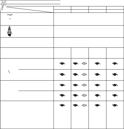
SPECIFICATIONS
Model |
Grass Trimmer |
Brush Cutter |
Grass Trimmer |
Grass Trimmer |
|
CG22EAS (SL) |
CG22EAS (S) |
CG22EAD (SL) |
CG22EAB (SL) |
||
|
Engine Size (ml) |
|
|
|
|
21.1 |
|
Spark Plug |
|
|
NGK BMR7A or equivalent |
|
||
Fuel Tank Capacity (l) |
|
|
|
|
0.45 |
|
Dry Weight (kg) |
|
4.4 |
|
4.7 |
4.7 |
4.0 |
Sound pressure level |
Equivalent |
|
|
|
|
|
LpA (dB (A)) |
90 |
89 |
91 |
90 |
90 |
|
(EN27917) |
|
|||||
Measured sound |
(ISO10884) |
|
|
|
|
|
power level LwA |
Equivalent |
104 |
104 |
103 |
104 |
104 |
(dB (A)) |
|
|||||
Measured sound |
(2000/14/EC) |
|
|
|
|
|
power level LwA |
Racing |
107 |
107 |
106 |
107 |
107 |
(dB (A)) |
|
|||||
Guaranteed sound |
(2000/14/EC) |
|
|
|
|
|
power level LwA |
Racing |
108 |
109 |
108 |
108 |
109 |
(dB (A)) |
|
|||||
Vibration level (m/s2) |
|
|
|
|
|
|
(ISO7916) |
|
|
|
|
|
|
Equivalent (Front / Left handle) |
6.7 |
4.5 |
4.7 |
7.7 |
5.5 |
|
Equivalent (Rear / Right handle) |
4.1 |
4.8 |
4.3 |
4.7 |
6.6 |
|
Idling (Front / Left handle) |
4.9 |
2.7 |
2.7 |
4.1 |
5.5 |
|
Idling (Rear / Right handle) |
3.3 |
3.4 |
3.4 |
3.7 |
4.7 |
|
Racing (Front / Left handle) |
8.0 |
5.8 |
6.1 |
10.1 |
5.5 |
|
Racing (Rear / Right handle) |
4.7 |
5.9 |
5.1 |
5.5 |
8.1 |
|
5

|
Model |
Grass Trimmer |
Brush Cutter |
Grass Trimmer |
Brush Cutter |
||
|
CG24EAS (SL) |
CG24EAS (S) |
CG27EAS (SL) |
CG27EAS (S) |
|||
|
|
||||||
Engine Size (ml) |
|
23.9 |
|
|
26.9 |
|
|
Spark Plug |
|
|
NGK BMR7A or equivalent |
|
|
||
Fuel Tank Capacity (l) |
|
|
|
|
0.52 |
|
|
Dry Weight (kg) |
|
4.6 |
|
4.9 |
4.9 |
|
5.1 |
Sound pressure level |
Equivalent |
|
|
|
|
|
|
LpA (dB (A)) |
92 |
92 |
93 |
93 |
93 |
95 |
|
(EN27917) |
|
||||||
Measured sound |
(ISO10884) |
|
|
|
|
|
|
power level LwA |
Equivalent |
105 |
105 |
105 |
107 |
107 |
107 |
(dB (A)) |
|
||||||
Measured sound |
(2000/14/EC) |
|
|
|
|
|
|
power level LwA |
Racing |
108 |
108 |
108 |
110 |
110 |
110 |
(dB (A)) |
|
||||||
Guaranteed sound |
(2000/14/EC) |
|
|
|
|
|
|
power level LwA |
Racing |
111 |
111 |
111 |
111 |
111 |
111 |
(dB (A)) |
|
||||||
Vibration level (m/s2) |
|
|
|
|
|
|
|
(ISO7916) |
|
|
|
|
|
|
|
Equivalent (Front / Left handle) |
6.2 |
3.7 |
8.4 |
6.2 |
4.8 |
8.6 |
|
Equivalent (Rear / Right handle) |
5.8 |
4.7 |
6.5 |
7.4 |
4.0 |
6.1 |
|
Idling (Front / Left handle) |
4.2 |
2.6 |
2.6 |
3.1 |
2.8 |
2.8 |
|
Idling (Rear / Right handle) |
3.1 |
4.4 |
4.4 |
2.0 |
3.9 |
3.9 |
|
Racing (Front / Left handle) |
7.7 |
4.6 |
11.6 |
8.3 |
6.2 |
11.9 |
|
Racing (Rear / Right handle) |
7.6 |
5.0 |
8.2 |
10.4 |
4.1 |
7.6 |
|
NOTE
Equivalent noise level/vibration level are calculated as the time-weighted energy total for noise/vibration levels under various working conditions with the following time distribution: 1/2 Idle, 1/2 racing.
* All data subject to change without notice.
ASSEMBLY PROCEDURES |
1 |
Drive shaft to engine (Fig. 1) |
|
Loosen tube locking bolt (1) about ten turns so that the bolt point will |
2 |
not obstruct drive shaft tube to be inserted. When inserting drive |
|
shaft tube, hold the tube locking bolt outward preventing inside |
|
fitting from obstructing as well. |
|
Insert the drive shaft into the clutch case of the engine properly until |
|
the marked position (2) on the drive shaft tube meets the clutch |
Fig. 1 |
case. |
|
Some models may come with the drive shaft already installed. |
|
6
NOTE
When it is hard to insert drive shaft up to the marked position on the drive shaft tube, turn drive shaft by the cutter mounting end clockwise or counter-clockwise. Tighten tube locking bolt lining up the hole in the shaft tube. Then tighten clamp bolt securely.
Installation of attachment
1. Join the attachment in place of it.
2. Make sure the lock pin (3) fits in the location hole (4) of tube and that the tube will not come o . (Fig. 2)
3. Tighten the knob nut (5) securely. (Fig. 2)
3
5
4
CG22EAD(S)
Fig. 2
Installation of handle
 WARNING
When you use steel/rigid blades on straight shaft trimmers or brush cutters, always use a barrier bar (6) and shoulder harness with the loop handle. (Fig. 3)
6
For Grass Trimmer
Fig. 3
Attach the handle to the drive shaft tube with the angle towards the engine.
Adjust the location to the most comfortable position before operation.
NOTE
If your unit has handle location label on drive shaft tube, follow the illustration.
Remove the handle bracket (7) from the assembly. (Fig. 4)
Place the handles and attach the handle bracket with four bolts lightly. Adjust to appropriate position. Then attach it firmly with the bolts.
7
Fig. 4 For Brush Cutter
Attach the protection tube to the drive shaft or handle using cord clamps (8). (Fig. 5)
8
Fig. 5 For Brush Cutter
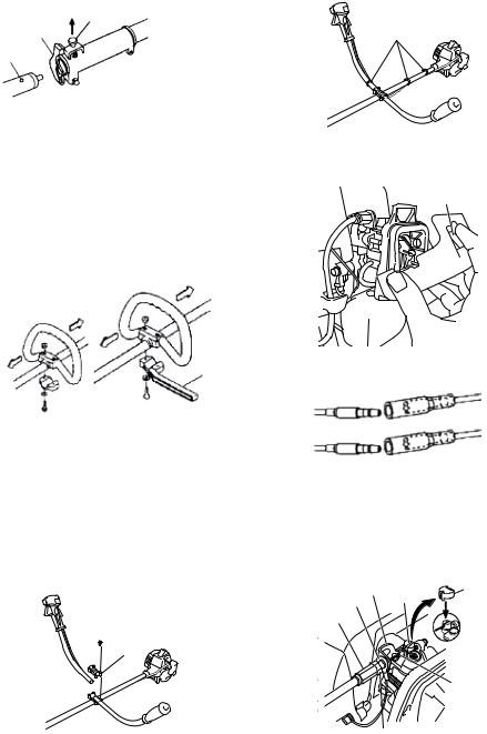
Throttle wire / stop cord
Press the upper tab (9) and open the air cleaner cover. (Fig. 6)
9
Fig. 6
Connect stop cords. (Fig. 7)
Fig. 7
If the throttle outer end (10) is threaded on your unit, screw it and the earth terminal (11) (if so equipped) into the cable adjuster stay (12) all the way, and then tighten this cable end using the adjuster nut (13) against the cable adjuster stay (12).
Connect throttle wire end (14) to carburetor (15) and install swivel cap (16) (if so equipped) where is included in tool bag, onto swivel (15) (Fig. 8).
Some models may come with the parts installed.
12 |
16 |
11 |
15 |
|
10
|
14 |
13 |
|
Fig. 8 |
7 |
|

Installation of blade guard (Fig. 9-a, 9-b, 9-c, 10)
 WARNING
○ Do not start or operate unit unless each guard is properly assembled to unit.
○ lf unit is operated without a sharp line limiters, the line will become too long, the engine will overheat, and engine damage may occur.
○ Check sharp line limiters surely cut nylon line when operating.
When using a trimmer head with two piece type blade guard, attach the guard extension to the blade guard. (Fig. 11)
Fig. 9-a
NOTE
The guard bracket may come already mounted to the gear case on some models.
Install the blade guard on drive shaft tube against angle transmission. Tighten the guard bracket firmly so that the blade guard does not swing or move down during operation.
Install the blade guard to the guard bracket, which also secures the guard to the gear case using the two guard mounting screws.
Fig. 9-b |
Fig. 9-c |
|
|
|
|
|
|
|
Only CG22EAB(SL)
Fig. 10
CAUTION
Some blade guards are equipped with sharp line limiters. Be careful with handling it.
Fig. 11
NOTE
○ When attaching the guard extension to the blade guard, the sharp line limiter must be removed from the blade guard, (if so installed).
○ If your unit has guard location label on drive shaft tube, follow the indication.
○ To remove the guard extension, refer to the drawings. Wear gloves as the extension has a sharp line limiter, then push the four square tabs on the guard one by one in order. (Fig. 12)
Fig. 12
Installation of semi-auto cutting head
1.Function
Automatically feeds more nylon cutting line when it is tapped at low rpm (not greater than 4500 rpm).
Specifications
Code No. |
Type of |
Direction of |
Size of |
|
attaching screw |
rotation |
attaching screw |
6696454 |
Female screw |
Counterclockwise |
M10×P1.25-LH |
6696597 |
Female screw |
Clockwise |
M8×P1.25-RH |
Applicable nylon cord |
Length: 2 m |
|
|
Cord diameter: Φ3.0 mm |
|
||
Cord diameter: Φ2.4 mm |
Length: 4 m |
|
|
8
 Loading...