


AX-F100-WUN
SERVICE MANUAL
MANUEL D'ENTRETIEN
WARTUNGSHANDBUCH
CAUTION:
Beforeservicing this chassis, itisimportantthat the servicetechnician read the“Safe ty
Precautions”and“ProductSafetyNotices”inthisservicemanual.
SM0100
AXF100E
AXF100EBS
AXF100UC
AXF100W
AXF100WUN
Data contained within this Service
manual is subject to alteration for
improvement.
ATTENTION:
Avantd’effectuerl’entretienduchâassis,letechniciendoitlireles«Précautionsdesécurité»
etles«Noticesdesécuritéduproduit»présentésdansleprésentmanuel.
VORSICHT:
VorÖffnendesGehäuseshatderService-Ingenieurdie„Sicherheitshinweise“und„Hinweise
zurProduktsicherheit“indiesemWartungshandbuchzulesen.
Les données fournies dans le présent
manueld’entretienpeuventfairel’objet
demodificationsenvuedeperfectionner
leproduit.
Die in diesem Wartungshandbuch
enthaltenenSpezifikationenkönnensich
zwecksVerbesserungenändern.
CONTENTS
SPECIFICATIONS...............................................................................................................................................3
SERVICE POINTS..............................................................................................................................................4
WIRING DIAGRAM.............................................................................................................................................8
PRINTED WIRING BOARD...............................................................................................................................9
CIRCUIT DIAGRAM...........................................................................................................................................17
BLOCK DIAGRAM.............................................................................................................................................29
EXPLODED VIEW.............................................................................................................................................31
REPLACEMENT PARTS LIST..........................................................................................................................35
SPECIFICATIONSANDPARTS ARE SUBJECT TO CHANGE FOR IMPROVEMENT
MINI COMPONENT HI-FI SYSTEM
September 2000

ENGLISH
SAFETY PRECAUTIONS
WARNING: The following precautions must be observed.
ALL PRODUCTS
Before any service is performed on the chassis an
isolation transformer should be inserted between the
power line and the product.
1. When replacing the chassis in the cabinet, ensure
all the protective devices are put back in place.
2. When service is required, observe the original
lead dressing. Extra precaution should be taken to
ensure correct lead dressing in any high voltage
circuitry area.
3. Many electrical and mechanical parts in
HITACHI products have special safety related
characteristics. These characteristics are often not
evident from visual inspection, nor can the
protection afforded by them necessarily be
obtained by using replacement components rated
for higher voltage, wattage, etc. Replacement
parts which have these special safety
characteristics are identified by marking with a
on the schematics and the replacement parts
list.
The use of a substitute replacement component
that does not have the same safety characteristics
as the HITACHI recommended replacement one,
shown in the parts list, may create electrical
shock, fire, X-radiation, or other hazards.
4. Always replace original spacers and maintain lead
lengths. Furthermore, where a short circuit has
occurred, replace those components that indicate
evidence of overheating.
5. Insulation resistance should not be less than 2M
ohms at 500V DC between the main poles and
any accessible metal parts.
6. No flashover or breakdown should occur during
the dielectric strength test, applying 3kV AC or
4.25kV DC for two seconds between the main
poles and accessible metal parts.
7. Before returning a serviced product to the
customer, the service technician must thoroughly
test the unit to be certain that it is completely safe
to operate without danger of electrical shock. The
service technician must make sure that no
protective device built into the instrument by the
manufacturer has become defective, or
inadvertently damaged during servicing.
CE MARK
1. HITACHI products may contain the CE mark on
the rating plate indicating that the product
contains parts that have been specifically
approved to provide electromagnetic
compatibility to designated levels.
2. When replacing any part in this product, please
use only the correct part itemised in the parts list
to ensure this standard is maintained, and take
care to replace lead dressing to its original state,
as this can have a bearing on the electromagnetic
radiation/immunity.
PICTURE TUBE
1. The line output stage can develop voltages in
excess of 25kV; if the E.H.T. cap is required to be
removed, discharge the anode to chassis via a
high value resistor, prior to its removal from the
picture tube.
2. High voltage should always be kept at the rated
value of the chassis and no higher. Operating at
higher voltages may cause a failure of the picture
tube or high voltage supply, and also, under
certain circumstances could produce X-radiation
levels moderately in excess of design levels. The
high voltage must not, under any circumstances,
exceed 29kV on the chassis (except for projection
Televisions).
3. The primary source of X-radiation in the product
is the picture tube. The picture tube utilised for
the above mentioned function in this chassis is
specially constructed to limit X-radiation. For
continued X-radiation protection, replace tube
with the same type as the original HITACHI
approved type
4. Keep the picture tube away from the body while
handling. Do not install, remove, or handle the
picture tube in any manner unless shatterproof
goggles are worn. People not so equipped should
be kept away while picture tubes are handled
LASERS
If the product contains a laser avoid direct exposure to
the beam when the cover is open or when interlocks are
defeated or have failed.
AX-F100
• The caution labels on laser usage • Notices de précautions d’emploi du laser
CLASS 1 LASER PRODUCT
LUOKAN 1 LASERLAITE
KLASS 1 LASERAPPARAT
CLASS 1 LASER PRODUCT
LUOKAN 1 LASERLAITE
KLASS 1 LASERAPPARAT
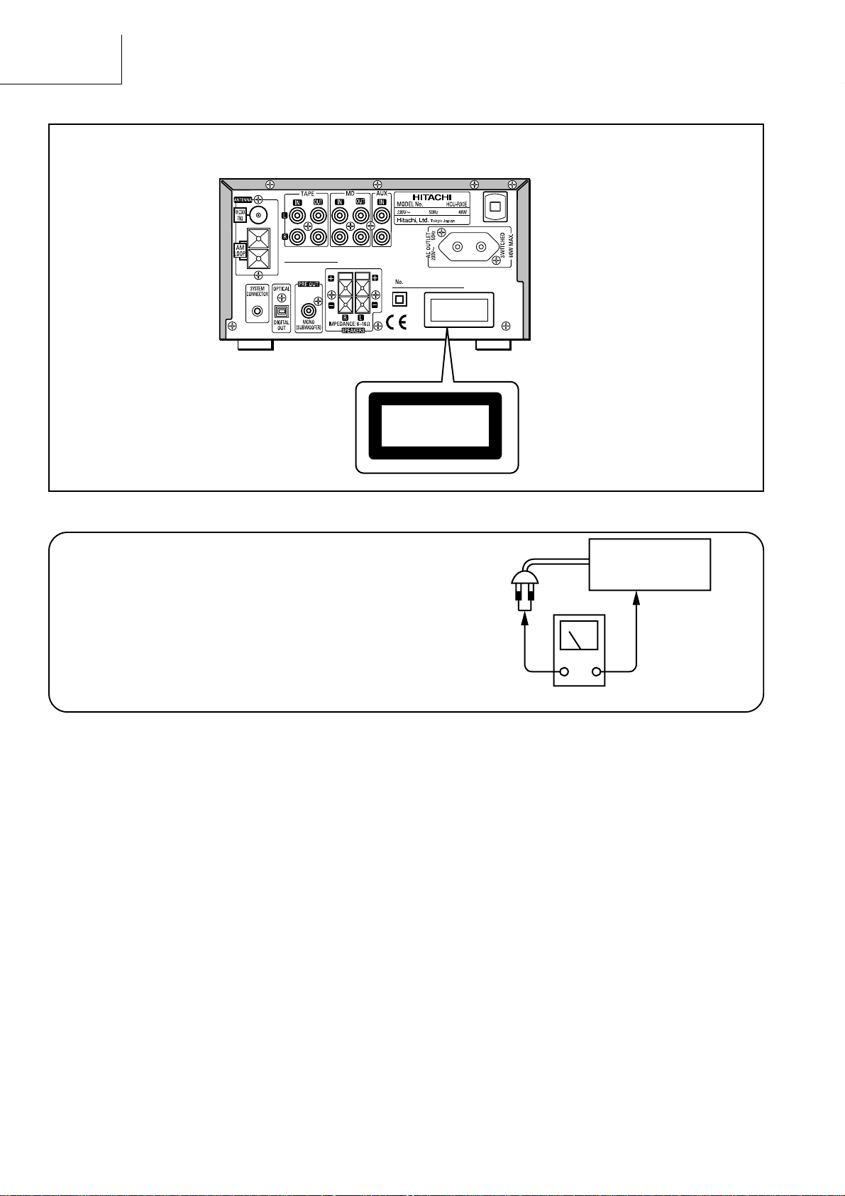
Check that exposed parts are acceptably insulated from
the supply circuit before returning the repaired instrument
to the customer.
• Checking method
Measure the resistance value between the both poles of
attachment cup (Power supply plug) and the exposed
parts (Parts such as Knob, Cover, etc. where the customer is easy to touch.) and check that the resistance
value is 500 kohms or more.
INSTRUMENT
(Exposed part)
Insulation tester (DC 500V)
2

SAFETY PRECAUTIONS
The following precautions should be observed when servicing.
1. Since many parts in the unit have special safety-related characteristics, always use genuine Hitachis replacement
parts. Especially critical parts in the power circuit block should not be replaced with other makers. Critical parts
are marked with in the circuit diagram.
2. Before returning a repaired unit to the customer, the service technician must thoroughly test the unit to ascertain
that it is completely safe to operate without danger of electrical shock.
SPECIFICATIONS• SPECIFICATIONS
RECEIVER SECTION
Tuner Range : FM: 87.5 - 108.0 MHz (0.1 MHz step) UC
: FM: 87.50 - 108.00 MHz (0.05 MHz step) E, EBS, W, WUN
: MW: 520 - 1,710 kHz (10 kHz step) UC, W, WUN
: MW: 522 - 1,611 kHz (9 kHz step) E, EBS, W, WUN
: LW: 153 - 281 kHz (1 kHz step) E, EBS
CD SECTION
Sampling Frequency : 44.1 kHz
Laser : Semiconductor laser
AX-F100
TIMER SECTION
System : Digital Quartz Clock
Display Format : 24-hour cycle E, EBS, W, WUN
12-hour cycle UC
Timer Accuracy : Within 60 seconds at monthly rate in normal room temperature
GENERAL SPECIFICATIONS
Power Supply : AC 110 - 127 V/220 - 240 V, 50/60 Hz W, WUN
: AC 120 V, 60 Hz UC
: AC 230 V, 50 Hz E, EBS
Power Consumption : 48 W (ECO-ON mode: less than 1 W) E, EBS, W, WUN
: 1.1 A include AC outlet (ECO-ON mode: less than 1 W) UC
Rated Output Power : 30 W + 30 W (6 ohms, THD 10%)
Inputs/Outputs : MD, TAPE, AUX, Optical Digital Out, Pre out, Headphone, System Connector
SPEAKER SECTION
System : 2 Way Bass Reflex Speaker System
Speaker Unit : Woofer: 10 cm ∞ 1, Tweeter: 5 cm ∞ 1
Impedance : 6 ohms
DIMENSIONS
HCU-R30 Unit : 210 (W) ∞ 120 (H) ∞ 325 (D) mm
Speaker Unit : 150 (W) ∞ 275 (H) ∞ 227 (D) mm
WEIGHT
HCU-R30 Unit : 4.4 kg
Speaker Unit : 3.0 kg (1 speaker)
ACCESSORY SUPPLIED : FM Antenna, AM LOOP Antenna,
Remote Control (RB-AXF3), Battery,
Edison plug adapter (For W, WUN only)
* Specifications are subject to change for performance improvement without notice.
3
AX-F100
SERVICE POINTS
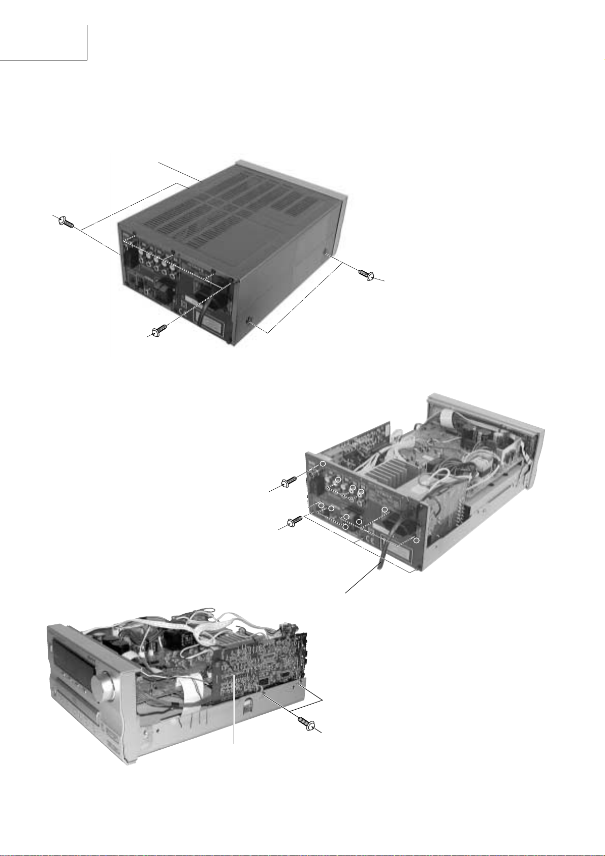
1. Removal of Top Cover
(1) Remove 4 screws 1 from each side.
(2) Remove 4 screws 2 from the rear plate.
Top cover
1
1
2
Fig. 1
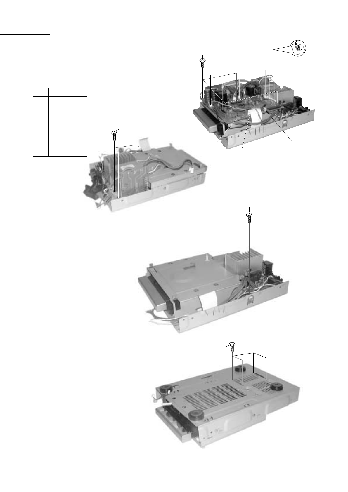
3. Removal of Tuner P.W.B Board
(1) Remove 2 screws 5.
(2) Pull the tuner P.W.B gently to detach from
connector A of the main PCB.
2. Removal of Rear Plate and Power Cord
(1) Remove 11 screws 3 and 4 from the rear plate.
(2) Detach the power cord.
1
3
4
4
2
3
Power cord
5
9
7
8
10
6
11
Fig. 2
Fig. 3
5
Connector A
4
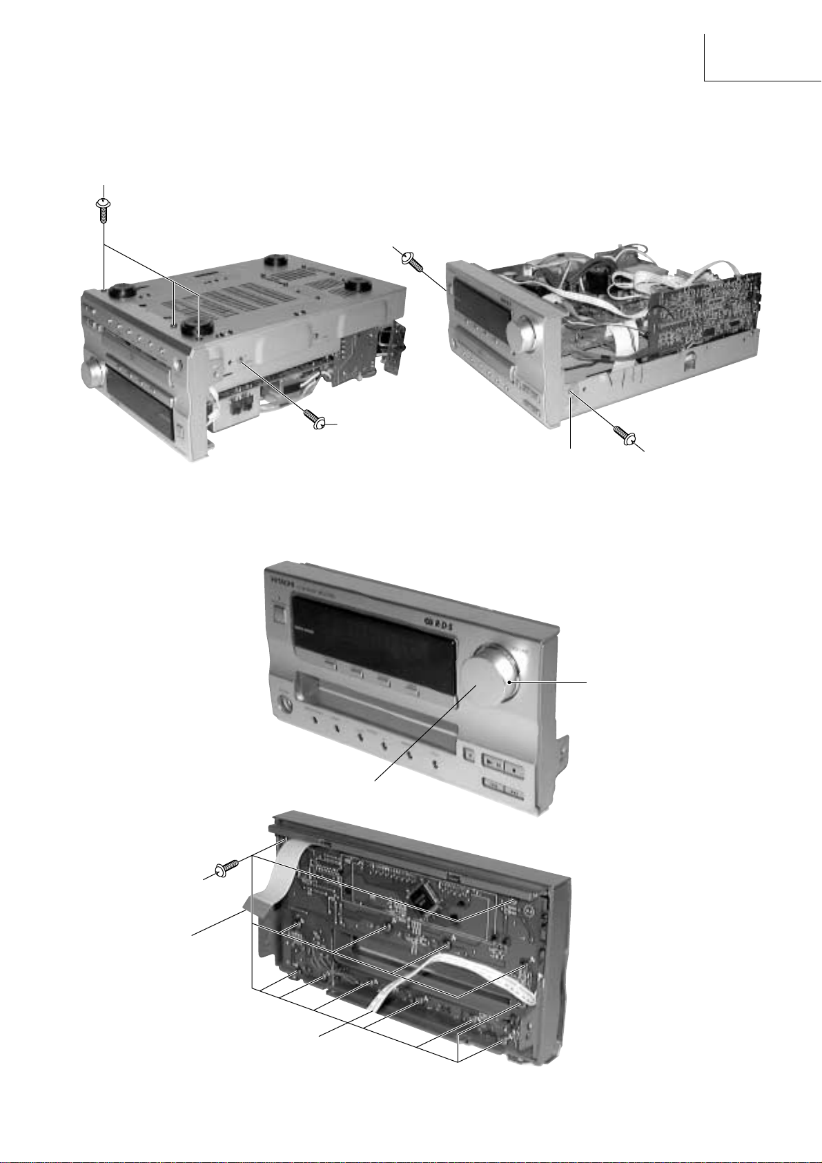
4. Removal of Front Panel
(1) Detach connector B & C (Refer to Fig. 5-2)
(2) Remove 3 screws 6 from base of front panel.
(3) Remove 1 screw 7 from each side and screw 8.
(4) Release the claw of the Inner panel from each side.
6
7
8
Fig. 4-1
Claw
AX-F100
Fig. 4-2
7
5. Removal of Front P.W.B Board
(1) Remove the volume knob to detach the nut.
(2) Remove 13 screws 9.
Fig. 5-1
Volume knob
9
Nut
Connector B
Fig. 5-2
Connector C
5
AX-F100
6. Removal of Main P.W.B Board and Power Transformer
(1) Detach the connector D to K.
(2) Remove 4 screws ! from base of the plate and 4
screws ".
(3) Press and push downwards the P.W.B. support.
(4) Gently pull the main P.W.B. upwards and remove
the Power Transformer.
No. CONNECTOR
D CN702
E CN701
F PG301
G PG302
H PG501
I PG601
J CN501
K PG505
L PG602
"
!
K
D
P.W.B. Support
I
J
E
H
G
F
Fig. 6-1
L
7. Removal of Amp P.W.B. Board
(1) Remove 1 screw #.
(2) Remove 4 screws $ from base of chassis.
Fig. 6-2
#
Fig. 7-1
$
6
Fig. 7-2
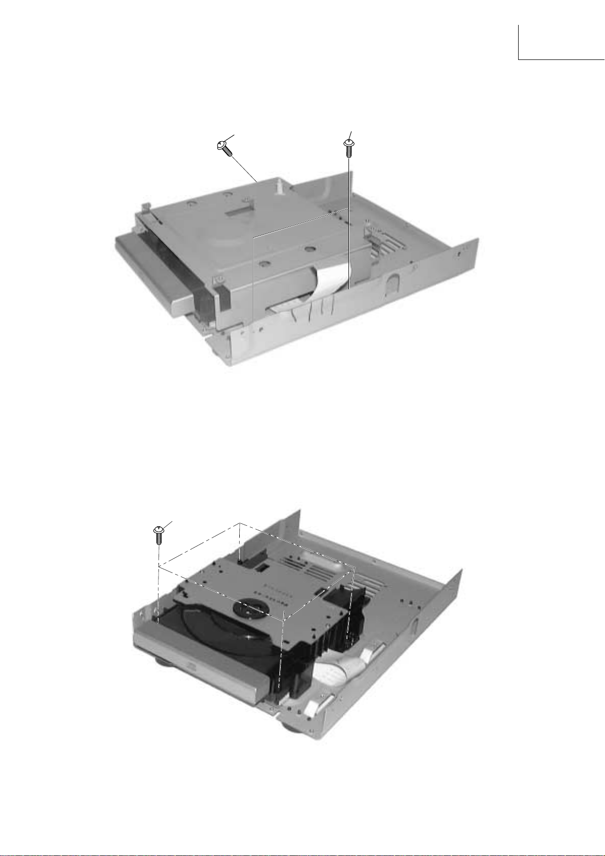
8. Removal of P.W.B. Holder
(1) Remove 3 screws % to detach the P.W.B. Holder.
AX-F100
%
%
Fig. 8
9. Removal of CD Mechanism Assembly
(1) Remove 4 screws & and pull up the CD mechanism.
&
Fig. 9
7
 Loading...