

Page 1
Installationsanleitung
Installation Instructions
Guide d’installation
Istruzioni di installazione
Instrucciones de instalación
Installationsanvisning
Installatie-instructies
Instruções de Instalação
Instrukcja instalowania
Инструкция по установке
Kurulum Talimatları
設置説明書
安装说明
安裝說明
MSE 1202
5/2014
Page 2
MSE 1202
Product overview
Complete Operating Instructions available at www.heidenhain.de
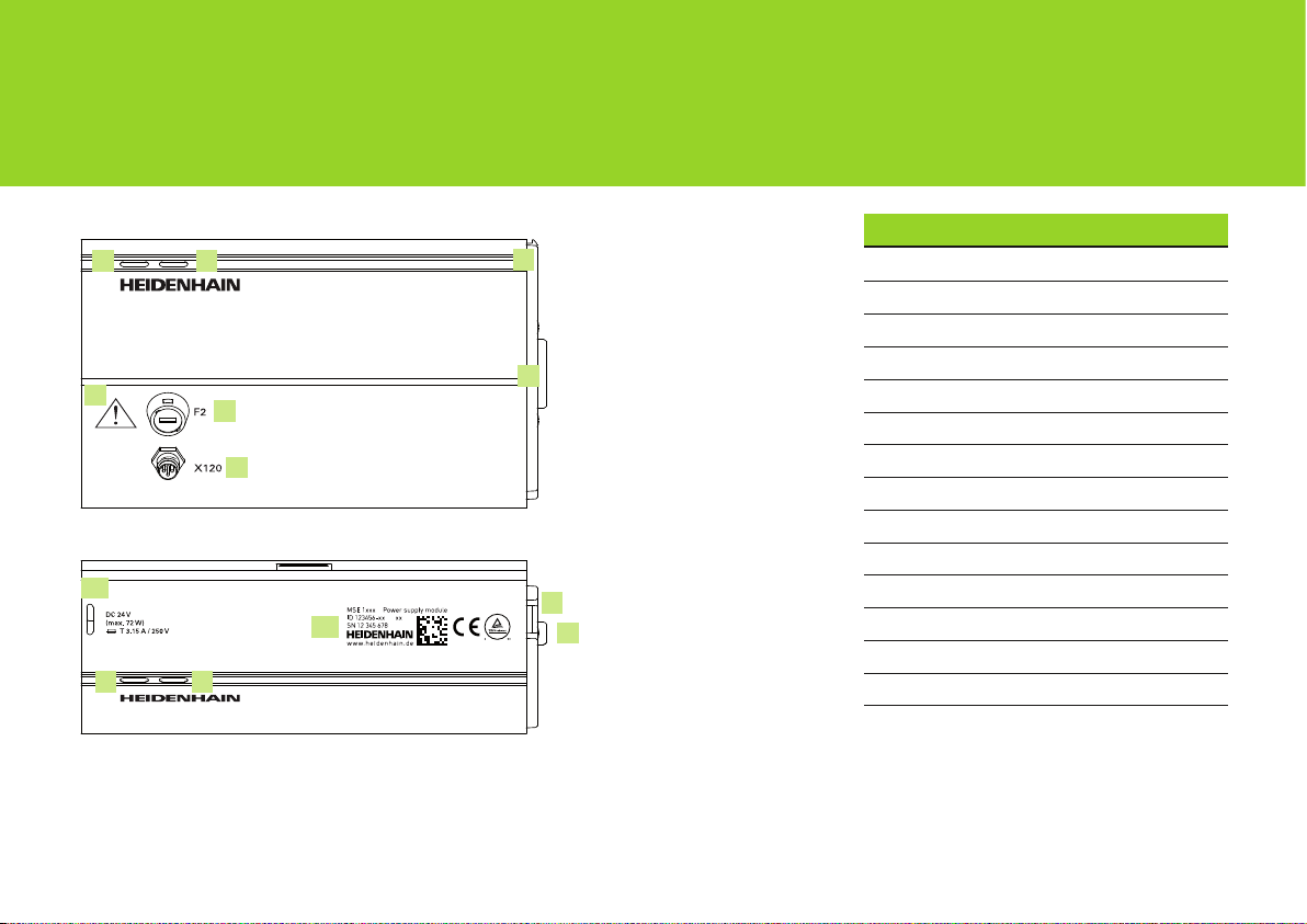
Front MSE 1202
1 2
3
4
5
Top MSE 1202
8
1 2
Languages
6
7
6
9
7
Deutsch .......................................................4
English ......................................................16
Français ....................................................28
Italiano .......................................................40
Español .....................................................52
Svenska ....................................................64
Nederlands ...............................................76
Português ..................................................88
J.polski ....................................................100
Русский ...................................................112
Türkçe .....................................................124
日本語 .....................................................136
Zhongwen (zh-CN) .................................148
Zhongwen (zh-TW) .................................160
2
Page 3
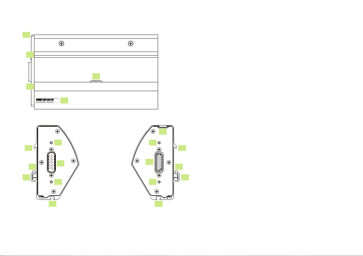
Rear MSE 1202
6
10
12
13
11
Left side MSE 1202
10
11
12
14
15
14
16
Right side MSE 1202
6
14
7
14
16
10
11
12
3
Page 4

MSE 1202
Installationsanleitung
Betriebsanleitung siehe www.heidenhain.de
Deutsch
1. Verwendung dieser Anleitung
Die vorliegende Installationsanleitung enthält alle für die Installation dieses Gerätes
notwendigen Informationen. Diese Informationen sind lediglich ein Auszug aus der
Betriebsanleitung (ID 1066850-xx). Die Betriebsanleitung steht unter www.heidenhain.de
zum Download zur Verfügung.
Die vorliegende Anleitung richtet sich an Personal, das befähigt ist, die
HEIDENHAIN MSE 1000 zu installieren und zu warten.
Eine qualifizierte Person ist aufgrund ihrer technischen Ausbildung, ihres Wissens
und ihrer Erfahrung sowie ihrer Kenntnisse des relevanten Regelwerks befähigt, die ihr
übertragenen Aufgaben zu beurteilen und mögliche Gefahren zu erkennen.
Inhaltsverzeichnis
Verwendung dieser Anleitung ....................4
Informationen zum Gerätetyp ....................6
Sicherheit ....................................................6
Technische Daten ........................................7
Montage......................................................8
Installation ................................................. 12
Erstinbetriebnahme .................................. 13
Wartung ....................................................14
4
Page 5
Hinweise in dieser Anleitung
Sicherheitshinweise, Warnhinweise auf mögliche Sachschäden und allgemeine Hinweise
werden in dieser Anleitung wie folgt dargestellt. Machen Sie sich zuerst mit diesen
Hinweisarten vertraut, um Personen- oder Sachschäden zu vermeiden.
Hinweis auf weitere Sicherheitshinweise. Diese ergänzenden Weisungen
beziehen sich nicht auf bestimmte Gefährdungen, sondern dienen der
Sensibilisierung und machen auf gezielte Sicherheitshinweise aufmerksam.
Warnung!
Hinweis, der über eine Gefährdung, die Folgen bei Nichtvermeidung einer
Gefährdung und die Möglichkeiten zur Vermeidung einer Gefährdung
informiert.
Hinweis
Allgemeiner Hinweis oder Hinweis, der hauptsächlich über das Risiko von
Sachschäden informiert, über die möglichen Folgen einer Nichtvermeidung
solcher Situationen oder Möglichkeiten zur Vermeidung solcher Situationen.
Darstellung von Begriffen in dieser Anleitung
Besonders wichtige Punkte oder Begriffe, auf die der Benutzer besonders aufmerksam
gemacht werden soll, sind fett gedruckt.
5
Page 6

2. Informationen zum Gerätetyp
Die vorliegende Kurzanleitung enthält die technischen Daten, sowie die Montage- und
Installationsanleitung für die folgenden Gerätetypen:
Produktname ID
MSE 1202 747502-01
9
Produktname ID
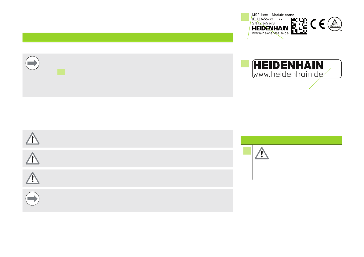
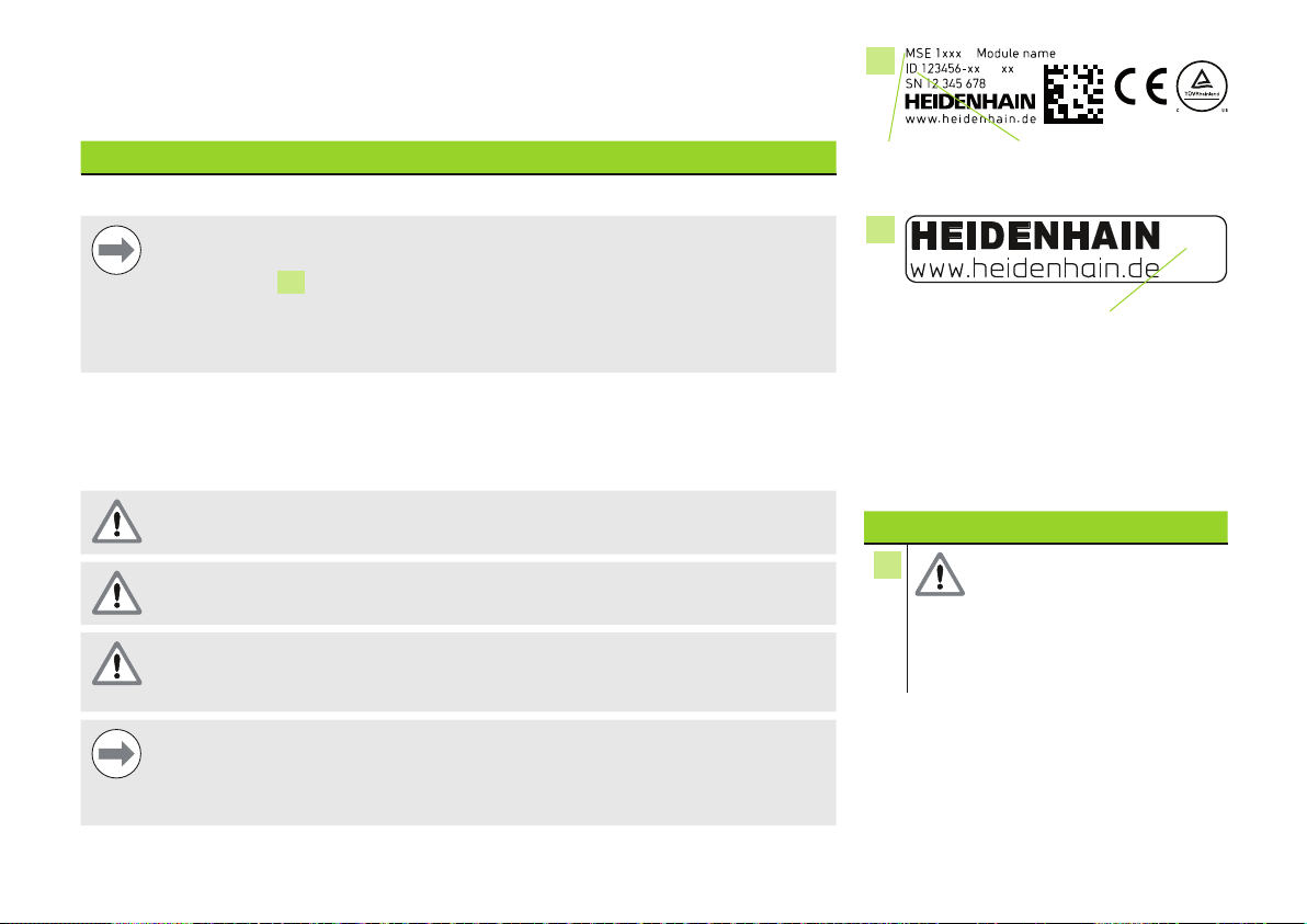
Typenschild
Hinweis
Überprüfen Sie, ob diese Installationsanleitung gültig ist, indem Sie den Index
auf dem Indexschild
vergleichen. Wenn die Anleitung nicht auf Ihr Gerät zutrifft, laden Sie die richtige
Installationsanleitung von www.heidenhain.de herunter.
Auf manchen Geräten ist eventuell kein Indexschild vorhanden.
mit dem unter www.heidenhain.de aufgeführten Index
13
3. Sicherheit
Die folgenden Hinweise enthalten sicherheitsrelevante Informationen zur Vermeidung von
Personen- oder Sachschäden:
Machen Sie sich zuerst mit den hier beschriebenen Anweisungen vertraut, um
Gefahren zu vermeiden, die zu Verletzungen oder Tod führen können.
Gerät nicht öffnen! Die im Gerät enthaltenen Bauteile sind wartungsfrei.
Der Schutzmechanismus des Gerätes kann durch nicht bestimmungsgemäßen
Gebrauch beeinträchtigt werden. Das Gerät darf nur gemäß seiner Bestimmung
verwendet werden.
Hinweis
Bewahren Sie dieses Dokument auf, falls Sie in Zukunft Informationen über
die Sicherheit, Bedienung und Handhabung des Gerätes nachschlagen wollen.
Bewahren Sie diese Anleitung so auf, dass sie sich in erreichbarer Nähe des
Geräts befindet.
13
Index
Indexschild
Sicherheitssymbole
Die folgenden Hinweissymbole auf
dem Produkt weisen auf wichtige
sicherheitsrelevante Informationen hin.
Symbolbeschreibung
3
Beachten Sie die
beiliegende Information
oder Dokumentation, um
Personen- oder Sachschäden
zu vermeiden.
6
Page 7
4. Technische Daten
Die MSE 1000 ist eine hochwertige, modulare Elektronik für hochgenaue, fertigungsnahe
Messungen. Die in dieser Anleitung beschriebenen Module sind nicht für die Verwendung
im Freien vorgesehen. Die Komponenten der MSE 1000 dürfen nur gemäß dieser
Anleitung installiert werden. Montage, Installation und Wartung dürfen nur von
qualifiziertem Personal durchgeführt werden.
MSE 1202
ID 747502-01
Versorgungsspannung
Ausgangsleistung
Austauschbare
Sicherung
Datenübertragung
Adressierung
Arbeitstemperatur
Lagertemperatur
Relative
Luftfeuchtigkeit
Höhe
Schutzart
Überspannungs-
kategorie
Verschmutzungsgrad
Masse
DC 24 V (±10 %)
(max. 72 W)
72 W
T 3,15 A / 250 V, 5 mm x 20 mm
Standard-Ethernet, IEEE 802.3
Feste IP-Adresse oder DHCP
0 °C ... 45 °C
-20 °C ... 70 °C
80 %
2000 m
IP 65
II, Energie verbrauchende Betriebsmittel, die von der festen
Installation gespeist werden
2
560 g
7
Page 8
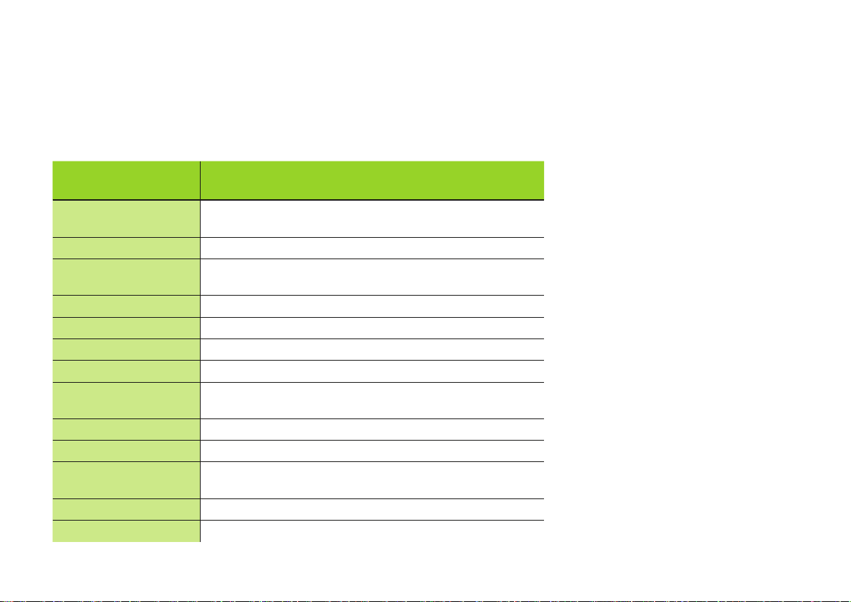
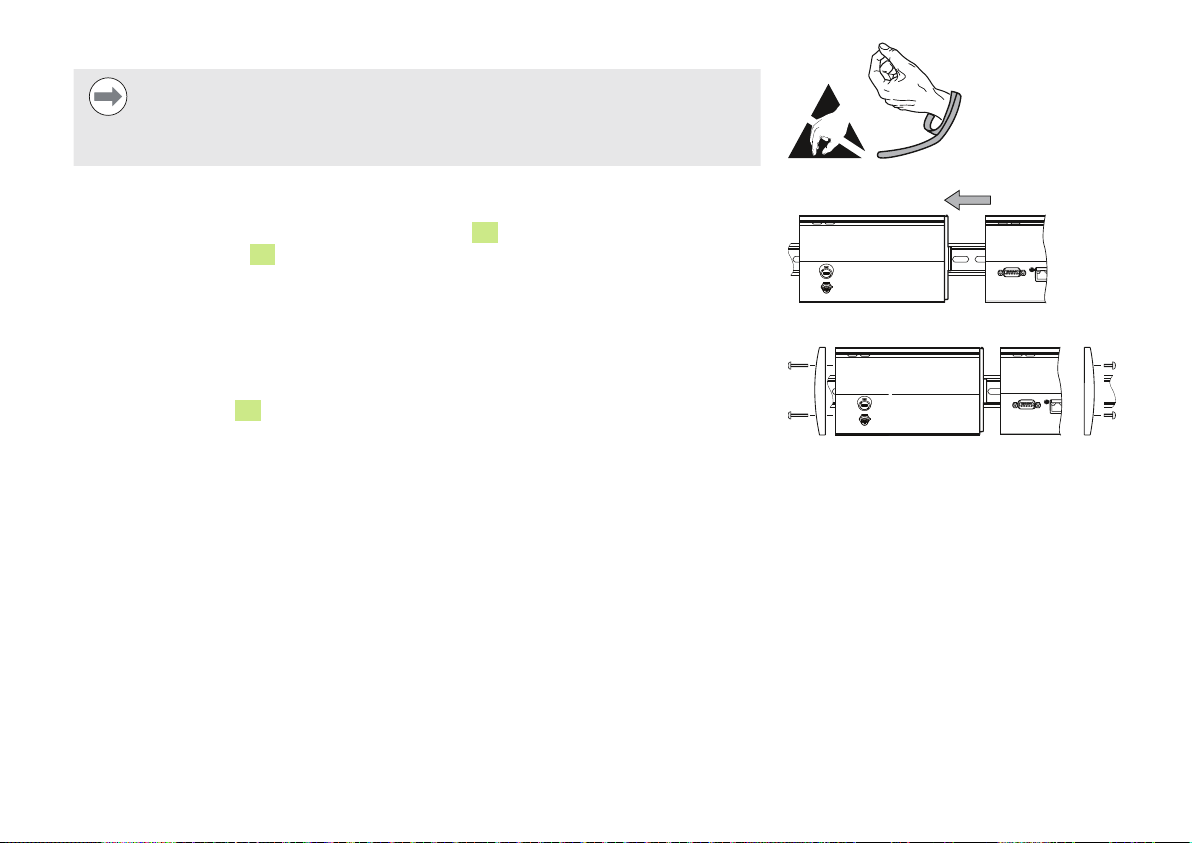
5. Montage
Bei der Montage auf leichte Zugänglichkeit des Netzkabels achten.
MSE-1000-Module lassen sich auf einer 35 mm-Standardhutschiene nach DIN EN 50022
im Schaltschrank oder auf Standfüßen (Zubehör) befestigen. Die einzelnen Module
werden aneinander gesteckt und über eine Klick-Arretierung zueinander fixiert, so dass
sich eine Modulkette ergibt.
Die MSE 1000 besteht in ihrer Grundkonfiguration aus Netzteil- und Basismodul. Sie kann
bei Bedarf durch zusätzliche Module erweitert werden. Insgesamt sind bis zu 250 Achsen
oder Kanäle konfigurierbar.
Abhängig vom Leistungsbedarf der Module, die dem Netzteilmodul in der Modulkette
folgen, und aller an diese Module angeschlossenen Geräte, werden möglicherweise
weitere Versorgungsmodule benötigt. Reicht die maximale Nennleistung eines
Versorgungsmoduls nicht aus, muss ein weiteres Versorgungsmodul in der Modulkette
verwendet werden. Maximale Nennleistung der Versorgungsmodule: Siehe “Technische
Daten“ auf Seite 7.
Hinweis
Berechnungsbeispiele für den Leistungsbedarf finden Sie in der
Produktinformation MSE 1000 (ID 736907-xx).
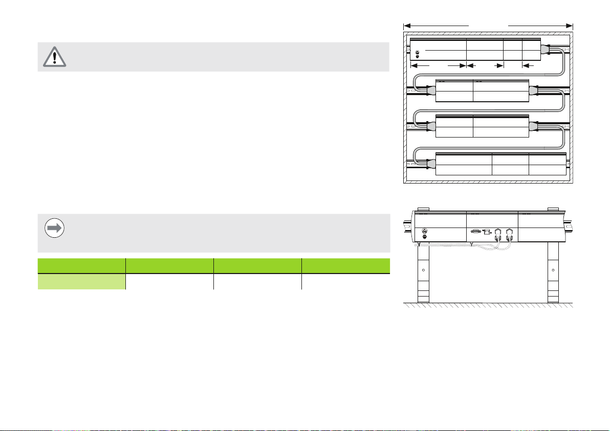
Modulgrößen Größe 1 Größe 2 Größe 3
Breite
53 mm 106 mm 159 mm
19” / 483 mm
Größe 3 Gr. 2 Größe 1
Montage im 19-Zoll-Schaltschrank
Standfüße (Zubehör)
8
Page 9
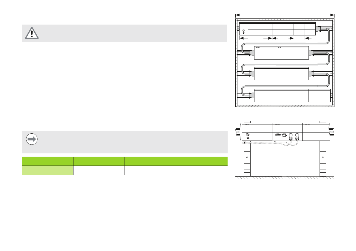
Montage eines Moduls
Hinweis
Eine Versorgungsmodul muss immer links von den Modulen angeordnet sein,
die es in der Modulkette versorgen soll. Reicht die maximale Nennleistung eines
Versorgungsmoduls nicht aus, muss ein weiteres Versorgungsmodul in der
Modulkette verwendet werden.
Modul befestigen:
Stromversorgung aller Versorgungsmodule der Modulkette abschalten
12
Modul mit unterer Nut
Hutschiene sanft nach oben drücken, dabei die Befestigungsfeder
bis die Hutschiene auf der unteren Nut
Oberseite des Moduls zur Hutschiene hin schwenken bis die obere Nut
auf Unterkante der Hutschiene aufsetzen
12
des Moduls einschnappt
11
niederdrücken
10
des Moduls
auf der Oberkante der Hutschiene aufsitzt, dabei weiter sanft nach oben drücken bis
die obere Nut des Moduls auf der Hutschiene einschnappt
Montage eines Moduls
9
Page 10
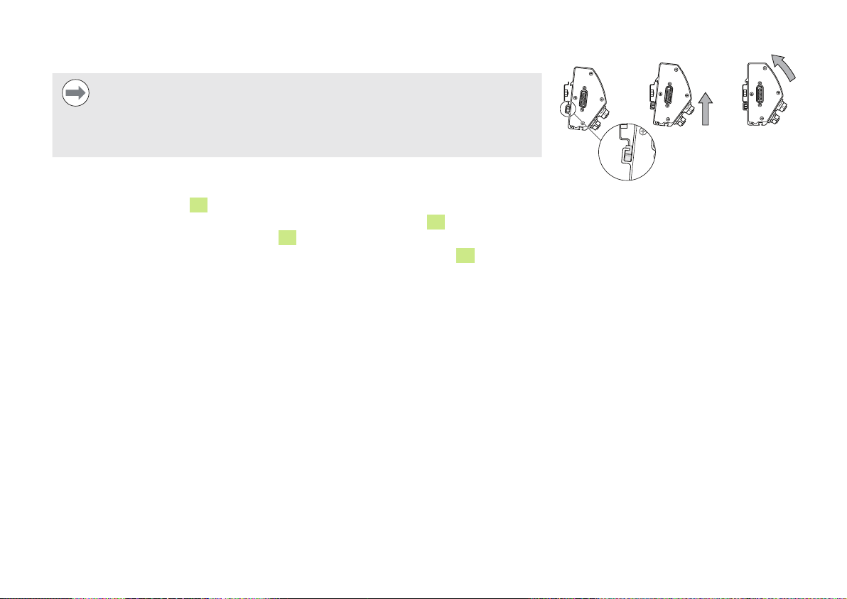
Module miteinander verbinden
Hinweis
Dieses Gerät enthält Bauteile, die durch elektrostatische Entladung (ESD)
beschädigt werden können. Beachten Sie die Sicherheitsvorkehrungen für die
Handhabung ESD-empfindlicher Bauteile und berühren Sie die Anschlussstifte
niemals ohne ordnungsgemäße Erdung.
Module miteinander verbinden:
Stromversorgung aller Versorgungsmodule der Modulkette abschalten
6
Rechtes Modul nach links schieben bis die Rastnase
vorgesehenen Schlitz
8
des rechten Moduls einrastet
des linken Moduls in den dafür
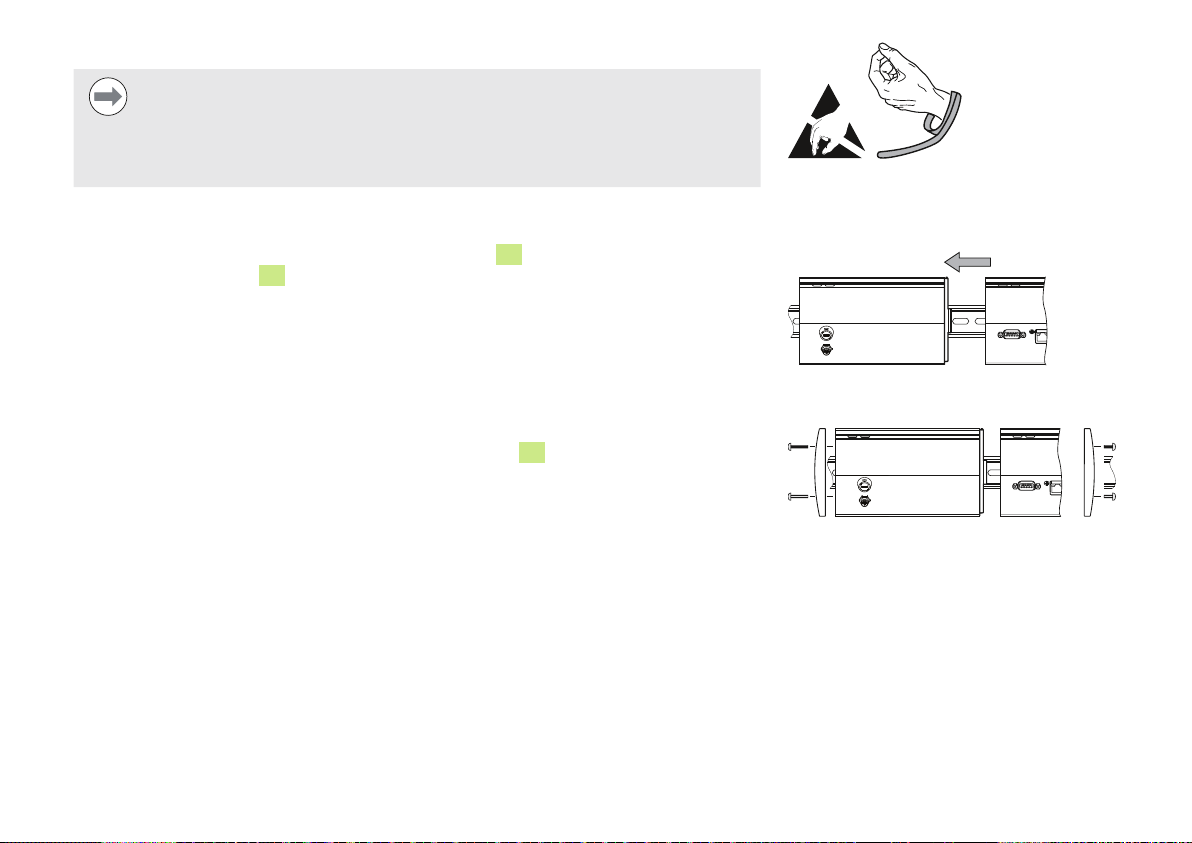
Abschlussblenden montieren
Alle Versorgungsmodule werden mit je einem Satz für eine linke und rechte
Abschlussblende geliefert, damit offene Modulseiten abgedeckt werden können.
Linke Abschlussblende in die linke Seite des ersten Versorgungsmoduls der Kette
einsetzen
19 mm-Schrauben der Abschlussblende durch die Befestigungsbohrungen der
Abschlussblende in die dafür vorgesehenen Bohrungen
Schrauben mit einem Kreuzschlitzschraubendreher festziehen
Rechte Abschlussblende in die rechte Seite des letzten Moduls der Kette unter
14
am Modul einstecken
Verwendung der mitgelieferten 9 mm-Schrauben wie oben beschrieben einsetzen
Sicherheitsvorkehrungen für die
Handhabung ESD-empfindlicher
Bauteile beachten
Module miteinander verbinden
Abschlussblenden montieren
10
Page 11
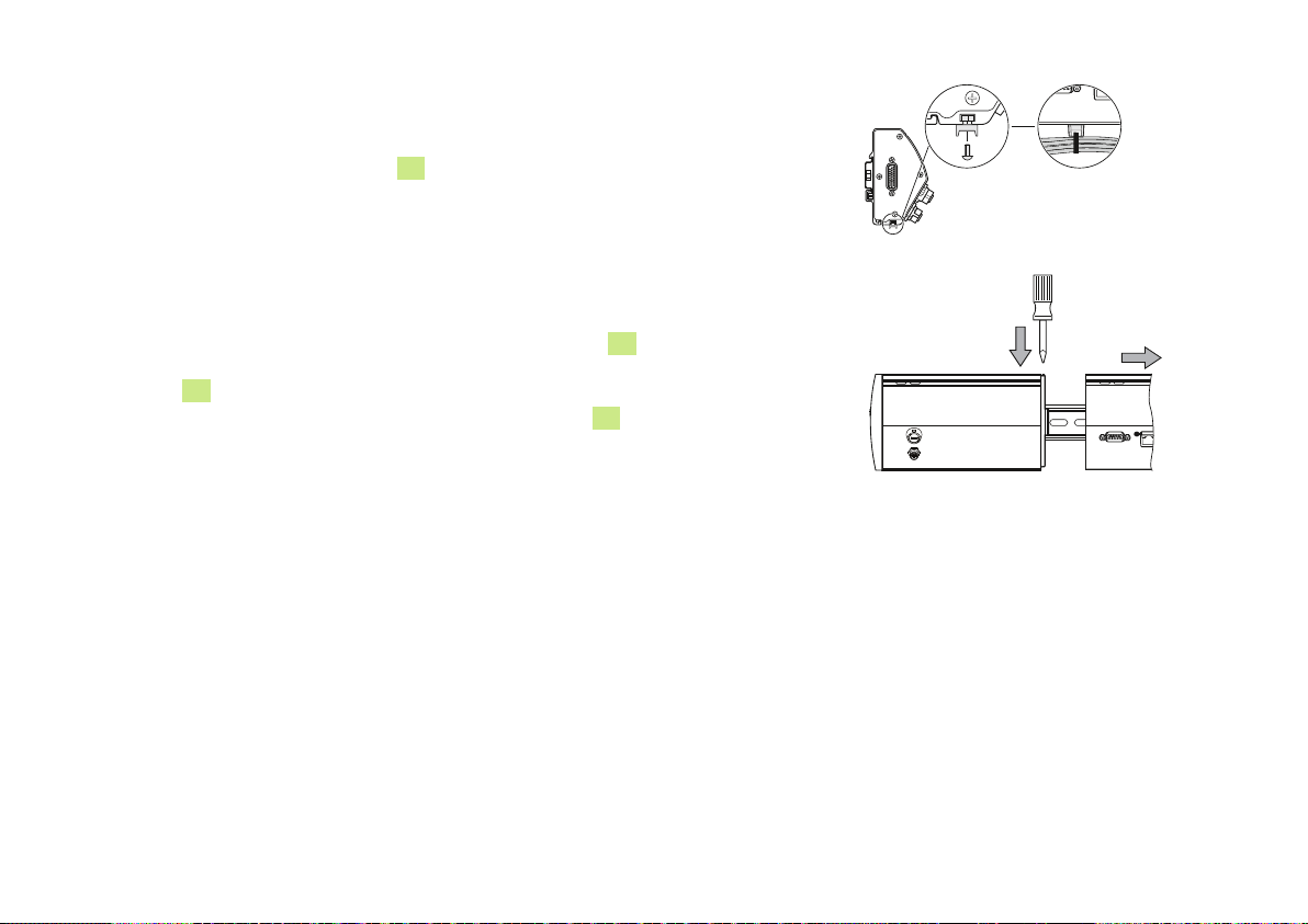
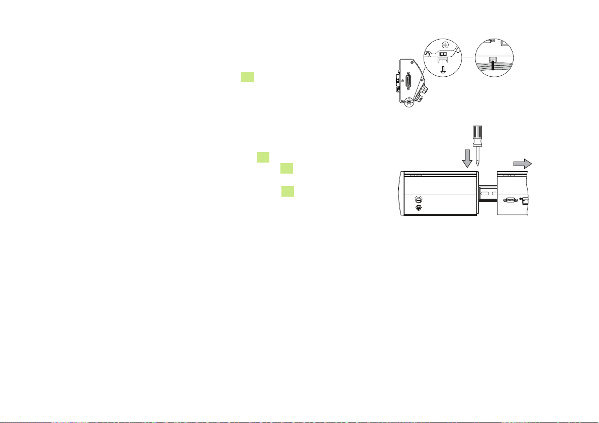
Befestigungselemente für Kabel montieren
Alle Module werden mit einem Befestigungsset zum Führen von Kabeln geliefert. Jedes
Befestigungsset enthält zwei Sätze Befestigungselemente.
16
Sechskantmutter M3 in Kabelkanal
Schraube M3 durch den Halter für den Kabelbinder stecken und mit einem
auf der Unterseite des Moduls einsetzen
Kreuzschlitzschraubendreher mit der Sechskantmutter M3 festschrauben
Kabelbinder durch den Halter schieben und Kabel befestigen
Modul entfernen
Stromversorgung aller Versorgungsmodule der Modulkette abschalten
8
Einen flachen Schraubendreher in die Öffnung des Schlitzes
stecken, der sich
oben links am rechten Modul befindet und in dem die Rastnase eingerastet ist, und die
Rastnase
Sanft nach oben drücken und dabei die Befestigungsfeder
Mit sanftem Druck nach oben die Oberseite des Moduls von der Hutschiene weg
6
des linken Moduls niederdrücken, damit es entfernt werden kann
11
niederdrücken
schwenken
Dann Druck nach oben langsam lösen und das Modul von der Hutschiene abnehmen
Modul entfernen
11
Page 12
6. Installation
Für die Sicherheit eines Systems, in dem dieses Gerät verwendet wird, trägt
der Monteur oder Installateur dieses Systems die Verantwortung.
Hinweis
Steckverbindungen nur bei ausgeschaltetem Gerät herstellen oder lösen!
Interne Bauteile könnten sonst beschädigt werden.
Elektrischer Anschluss
Warnung! Stromschlaggefahr!
Bei nicht ordnungsgemäßer Erdung des Gerätes besteht Stromschlaggefahr.
Verwenden Sie zur Vermeidung dieser Gefahr immer ein 3-poliges Netzkabel
und stellen Sie den korrekten Erdungsanschluss an die Gebäudeinstallation
sicher.
Warnung! Brandgefahr!
Wenn das verwendete Netzkabel nicht die Mindestanforderungen erfüllt,
besteht Brandgefahr.
Verwenden Sie zur Vermeidung dieser Gefährdung immer Netzkabel, die die
in der rechts abgebildeten Netzkabel-Tabelle aufgeführten Anforderungen
erfüllen.
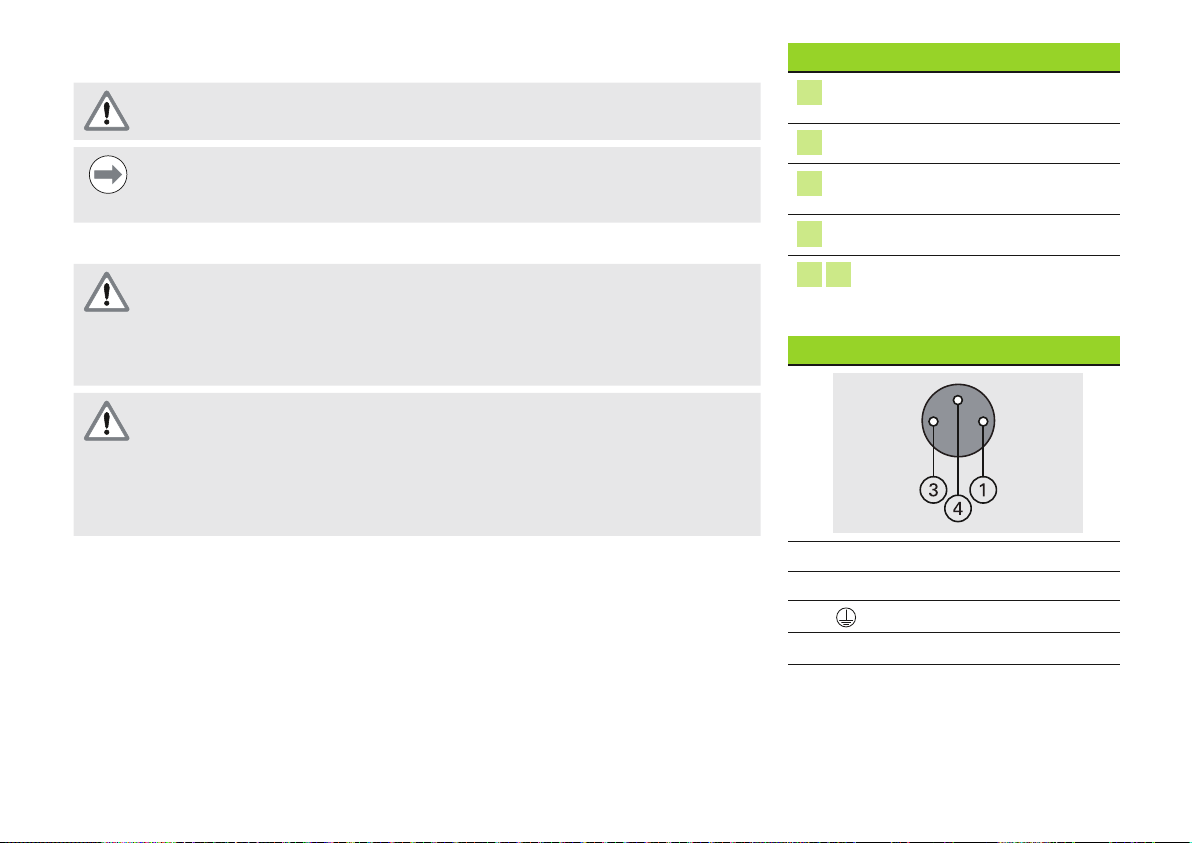
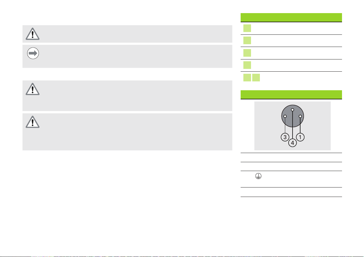
Schnittstellen
1
2
4
5
7 15
Netzkabel
1
3
4
Mindestquerschnitt: 0,24 mm
Max. Querschnitt: 0,35 mm
Status-LED für
Stromversorgung
Status-LED für Netzwerk
F2: Halterung für
austauschbare Sicherung
X120: Netzstecker
Modulanschlüsse
DC 24 V
0 V
Schutzleiteranschluss
2
2
12
Page 13
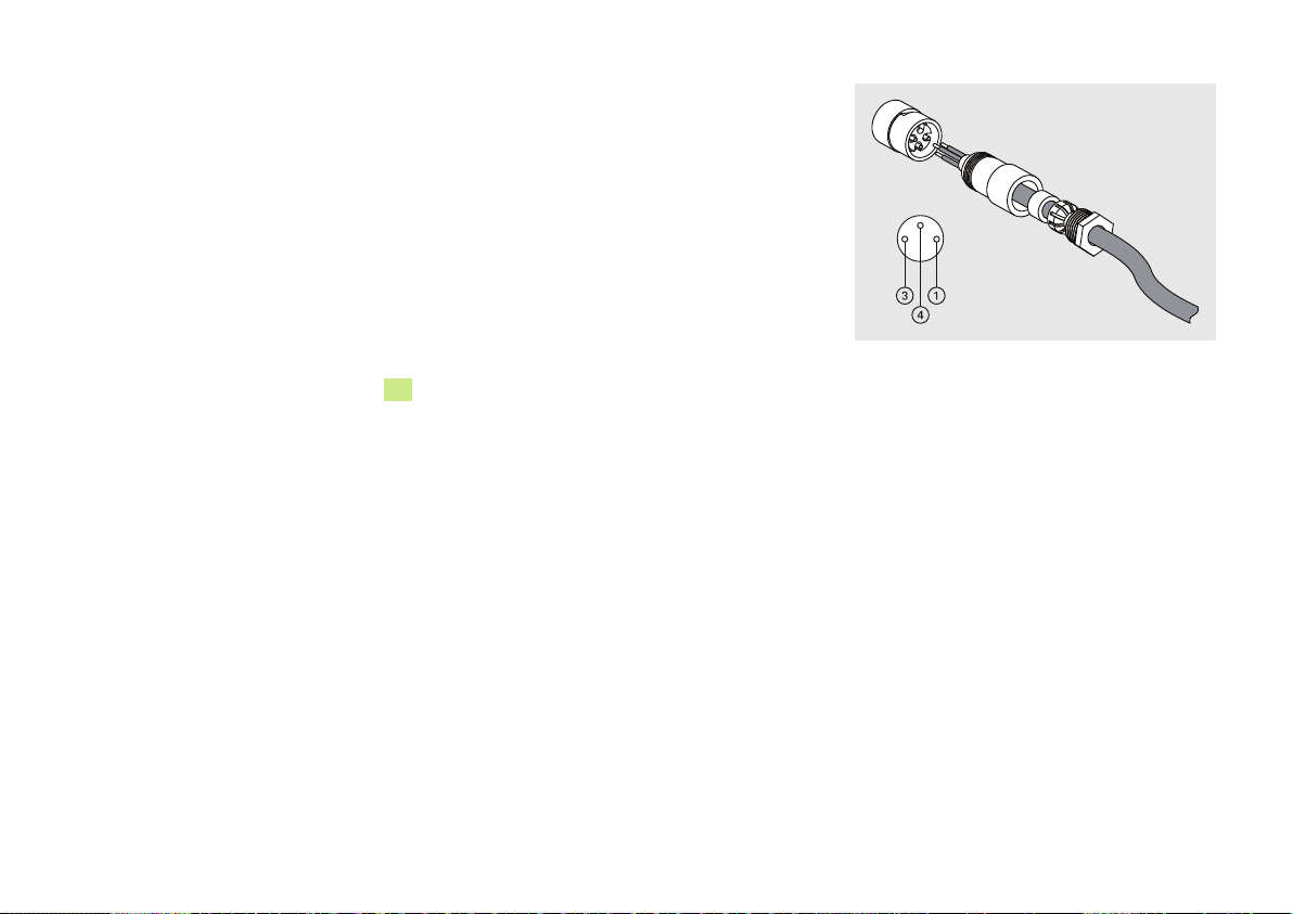
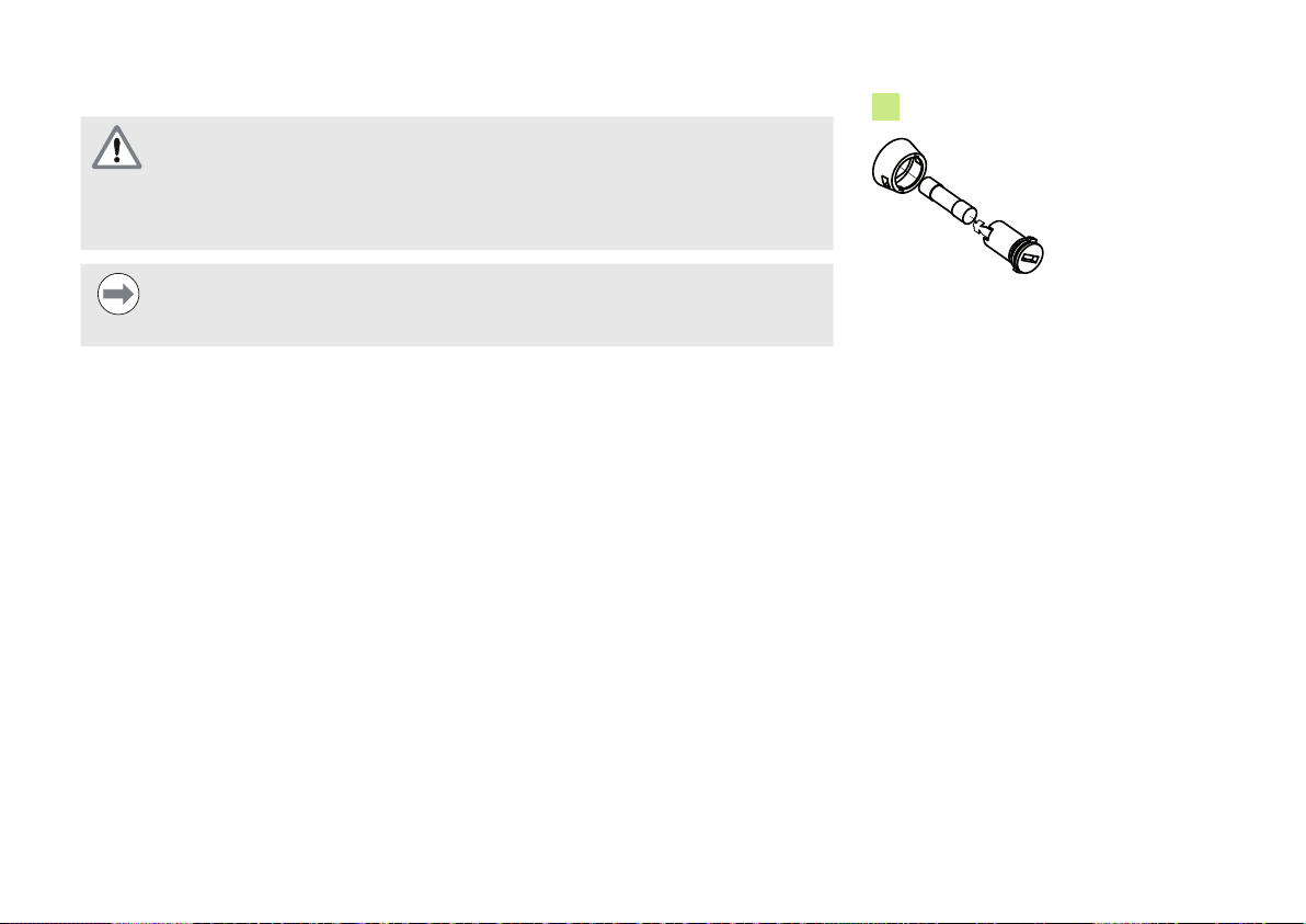
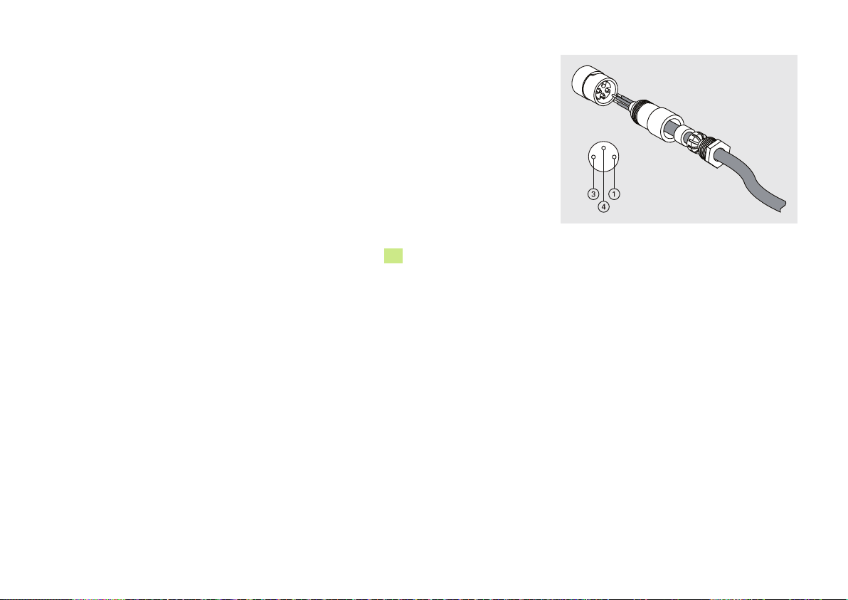
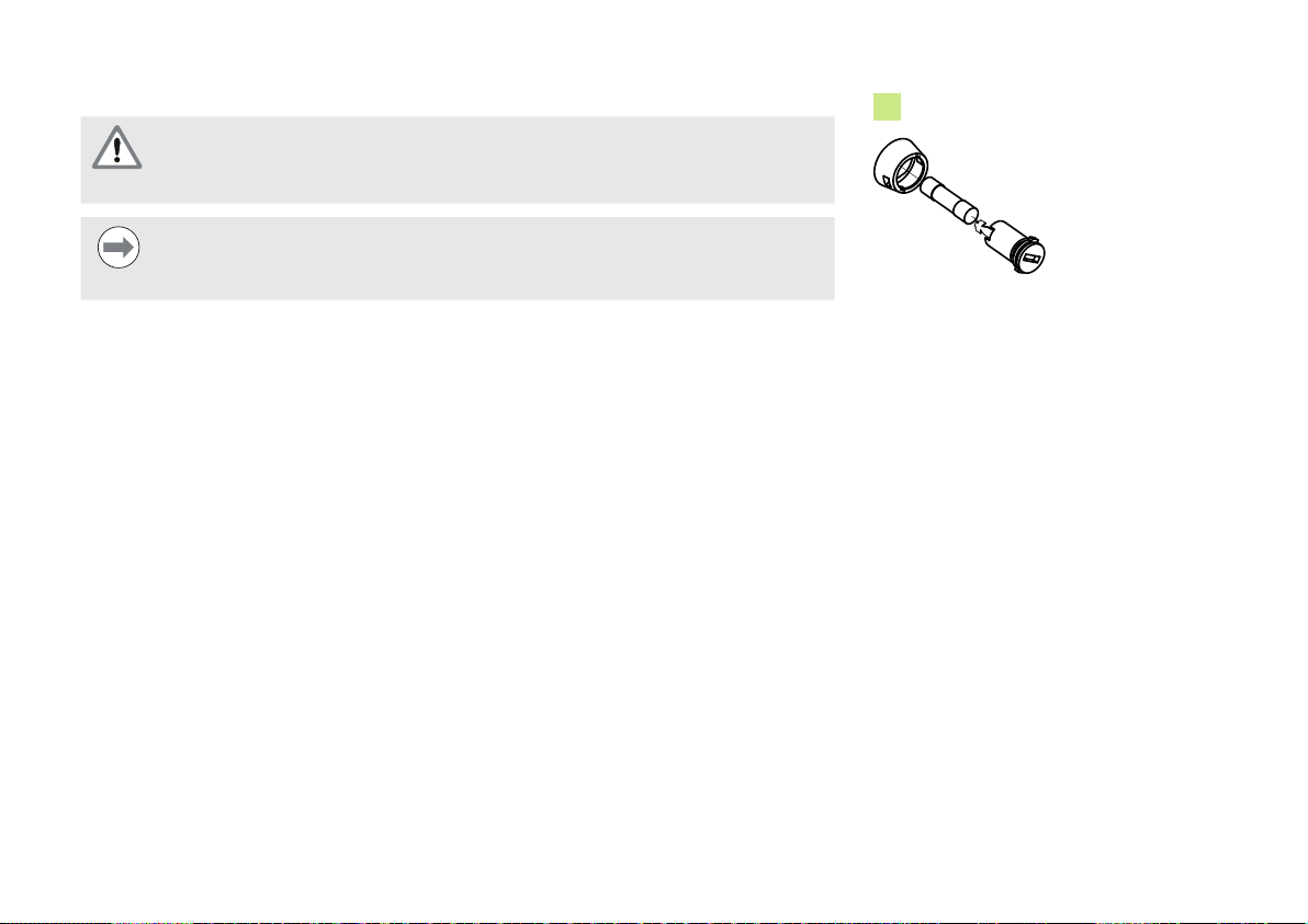
Verdrahtung der Netzkupplung
Die mit der MSE 1202 mitgelieferte M8-Kupplung (ID 1071955-01) muss mit einem
geeigneten Netzkabel verdrahtet werden, siehe “Netzkabel“ auf Seite 12.
Ersatzkupplungen sind von HEIDENHAIN erhältlich.
Netzkupplung verdrahten:
Netzkabel von der Hauptstromversorgung trennen
Netzkupplung verdrahten wie in der Abbildung rechts dargestellt
Netzkabel anschließen
Netzkabel anschließen:
Netzkabel von der Hauptstromversorgung trennen
Kupplung des Kabels auf den Anschluss am Modul ausrichten
5
Netzkupplung an den Netzstecker
M8-Kupplung handfest anziehen
auf der Vorderseite des Moduls anschließen
7. Erstinbetriebnahme
Gerät einschalten:
Stromversorgung des Geräts einschalten
Verdrahtung der M8-Netzkupplung
13
Page 14
8. Wartung
Die in dieser Anleitung beschriebenen Wartungsarbeiten können bei der Installation
des Gerätes erforderlich sein. Weitere Informationen zur Wartung finden Sie in der
Betriebsanleitung (ID 1066850-xx).
Reinigung
Warnung! Stromschlaggefahr!
Bei der Reinigung besteht die Gefahr eines Stromschlags durch Eintreten von
Flüssigkeit in das Gerät.
Zur Vermeidung dieser Gefahr muss das Gerät stets ausgeschaltet und das
Netzkabel gezogen werden. Verwenden Sie niemals ein durchfeuchtetes oder
vor Feuchtigkeit triefendes Tuch.
Hinweis
Verwenden Sie keine scheuernden oder aggressiven Reinigungs- oder
Lösungsmittel, um das Gerät nicht zu beschädigen.
Gerät reinigen:
Stromversorgung aller Versorgungsmodule der Modulkette abschalten
Außenflächen mit einem mit Wasser und einem milden Haushaltsreiniger
angefeuchteten Tuch abwischen
14
Page 15
Sicherung austauschen
Warnung! Stromschlaggefahr!
Beim Austausch einer Sicherung besteht die Gefahr, gefährliche,
spannungsführende Teile zu berühren.
Schalten Sie zur Vermeidung dieser Gefährdung das Gerät stets aus und
trennen Sie das Netzkabel von der Stromversorgung.
4
Hinweis
Um eine Beschädigung des Gerätes zu vermeiden, dürfen nur
spezifikationsgemäße Ersatzsicherungen verwendet werden.
Sicherung austauschen:
Stromversorgung des Moduls abschalten
Einen flachen Schraubendreher in den Schlitz an der Sicherungshalterung schieben und
im Gegenuhrzeigersinn drehen, um die Sicherungshalterung zu lösen
Sicherungshalterung abnehmen und Sicherung austauschen
Sicherungshalterung wieder einsetzen und mit einem flachen Schraubendreher im
Uhrzeigersinn drehen, bis sie wieder einrastet
Sicherungshalterung
15
Page 16

MSE 1202
Installation Instructions
Operating Instructions available at www.heidenhain.de
English
1. How to use these instructions
The installation instructions contained in this document provide the information necessary
to install this product. This information is just a part of the information available in the
Operating Instructions (ID 1066850-xx). The Operating Instructions can be downloaded
from www.heidenhain.de.
These instructions are intended for use by personnel qualified to install and maintain the
HEIDENHAIN MSE 1000.
A qualified person is someone whose technical education, knowledge and experience,
as well as knowledge of the relevant system of rules qualifies the person to evaluate the
delegated task and recognize possible hazards.
Contents
How to use these instructions .................16
Model information ....................................18
Safety ........................................................18
Specifications ............................................ 19
Mounting ...................................................20
Installation .................................................24
Initial power-up ..........................................25
Maintenance .............................................26
16
Page 17
Messages shown in these instructions
The following examples show how safety, property damage and general advice messages
are shown in these instructions. Read and understand these types of messages before
proceeding to prevent personal injury or property damage.
Messages about other safety messages. These supplemental directives do
not address specific hazards, but instead provide information that promotes
awareness and use of specific safety messages.
Warning!
Messages that provide information about the nature of a hazardous situation,
the consequences of not avoiding a hazardous situation, and methods for
avoiding a hazardous situation.
Notice
Messages that provide information primarily about situations that can lead to
property damage, the potential consequences of not avoiding the situations, or
methods for avoiding the situations and general advice messages.
Fonts used in these instructions
Items of special interest or concepts that are emphasized to the user are shown in bold
type.
17
Page 18
2. Model information
This guide covers specifications, mounting and installation for the following models:
Product name ID
MSE 1202 747502-01
Notice
Verify that these Installation Instructions are valid by matching the Index on the
label
not valid, download the applicable Installation Instructions from
www.heidenhain.de.
An index may not be present on all products.
with the Index listed at www.heidenhain.de. If these instructions are
13
9
Product name ID
ID label
13
Index
Index label
3. Safety
The following messages provide safety information for preventing personal injury and
product damage:
Read and understand these instructions before use to avoid the possibility of
personal injury or death.
Do not open the unit. There are no serviceable items inside.
The protection provided by the equipment may be impaired if used in a manner
not specified. Do not use this product in any way other than its intended use.
Notice
For safety, operation and handling of the unit, keep this document for future
reference. This document must be kept within reaching distance of the product.
Safety symbols
Where the following safety symbols
appear on the product they alert you to
important safety information.
Symbol description
3
Refer to the accompanying
information or
documentation to protect
against personal injury or
damage to the unit
18
Page 19

4. Specifications
The MSE 1000 is an advanced system for performing production integrated
measurements at high levels of precision and accuracy. The modules described in these
instructions are designed for indoor use only. The MSE 1000 components shall only be
installed as described in these instructions. Mounting, installation and maintenance are to
be performed by qualified personnel only.
MSE 1202
ID 747502-01
Power input
Rated power output
Replaceable fuse
Data transfer
Addressing
Operating temperature
Storage temperature
Relative humidity
Altitude
Degree of protection
Overvoltage category
Pollution degree
Mass
DC 24 V (±10 %)
(max. 72 W)
72 W
T 3.15 A / 250 V, 5 mm x 20 mm
Standard Ethernet, IEEE 802.3
Fixed IP address or DHCP
0 °C ... 45 °C
-20 °C ... 70 °C
80 %
2000 m
IP65
II, intended to be supplied from the building wiring
2
560 g
19
Page 20
5. Mounting
Do not mount in a position that makes it difficult to access the power cable.
MSE 1000 modules are designed to be mounted on a standard 35 mm, DIN EN 50022
rail in an electrical cabinet or on a mounting stand (accessory). The individual modules are
plugged onto each other and fixed together with a lock creating a module chain.
In its basic configuration, the MSE 1000 consists of a power supply module and a base
module. It can be expanded by further modules as needed. In all, up to 250 axes or
channels can be configured.
Multiple power supply modules may be needed based on the power consumption of the
modules following the power supply in the module chain and any equipment connected
to those modules. When the maximum power rating of a power supply module is reached
it is necessary to install another power supply module into the module chain. Refer to
“Specifications” on page 19 for maximum power consumption rating of power supply
modules.
Notice
Refer to the MSE 1000 Product Information (ID 736907-xx) for power
consumption calculation examples.
Module sizes Size 1 Size 2 Size 3
Width
53 mm 106 mm 159 mm
19” / 483 mm
Size 3 Size 2 Size 1
19”electrical cabinet mounting
Mounting stand (accessory)
20
Page 21

Mounting a module
Notice
A power supply module must always be to the left of any modules it is
powering in the module chain. Once the maximum power consumption rating
of a power supply module is reached, install another power supply module into
the module chain.
To mount a module:
Verify power is removed from all power supply modules in the module chain
12
Align the bottom edge of the DIN rail with the bottom channel
Gently apply upward pressure, depressing the DIN rail spring
rail into the bottom channel
While maintaining upward pressure, rotate the top of the module towards the DIN rail
until the top channel
Gently release the upward pressure, locking the module onto the DIN rail
12
of the module
10
of the module is aligned above the DIN rail
of the module
11
and inserting the DIN
Mounting a module
21
Page 22
Connecting modules
Notice
This product contains components that can be damaged by electrostatic
discharge (ESD). Observe precautions for handling ESD sensitive devices and
never touch connector pins unless properly grounded.
To connect modules:
Verify power is removed from all power supply modules in the module chain
6
Slide the right module to the left until the lock tab
the lock tab receiver
8
of the right module
of the left module engages with
Installing end covers
Left and right end cover kits are provided with each power supply module for covering
open module ends.
Insert the left end cover into the left side of the first power supply module in the chain
Insert 19 mm end cover screws through the end cover mounting holes and into the end
cover screw holes
Using a cross-head screwdriver, tighten the screws
Install the right end cover onto the right side of the last module in the chain using the
14
on the module
provided 9 mm screws and following the instructions given above
Observe ESD handling precautions
Connecting modules
Installing end covers
22
Page 23
Installing cable mounting hardware
A cable mounting hardware kit is provided with each module for routing cables. Each kit
contains two sets of mounting hardware.
16
Insert the M3 hex nut into the cable mounting slot
Insert the M3 screw through the cable tie holder and fasten to the M3 hex nut using a
on the bottom of the module
cross-head screwdriver
Insert the cable tie through the cable tie holder and fasten cables
Releasing a module
Verify power is removed from all power supply modules in the module chain
8
Press a flat-edge screwdriver into the lock tab receiver
left of the right hand module and press down on the lock tab
opening at the top
6
of the left hand
module to release the module
Gently apply upward pressure, depressing the DIN rail spring
While keeping upward pressure, rotate the top of the module away from the DIN rail
Gently release the upward pressure, releasing the module from the DIN rail
11
Releasing a module
23
Page 24
6. Installation
The safety of any system incorporating the use of this product is the
responsibility of the assembler or installer of the system.
Notice
Do not engage, or disengage any connections while the unit is under power.
Damage to internal components may result.
Interfaces
1
2
4
5
Power indicator LED
Network indicator LED
F2: Replaceable fuse holder
X120: Power connector
Electrical connection
Warning! Risk of electrical shock
A risk of electrical shock exists if this product is not properly grounded.
To avoid the hazard, always use a 3-conductor (grounded) power cord and
ensure the ground is properly wired to the building installation.
Warning! Risk of fire
A risk of fire exists if a power cord not meeting minimum specifications is
used.
To avoid the hazard, always use power cords that meet the specifications listed
in the Power cord table on the right.
7 15
Power cord
1
3
4
Min. wire cross section: 0.24 mm
Max. wire cross section: 0.35 mm
Module connectors
DC 24 V
0 V
Protective conductor (ground)
terminal
2
2
24
Page 25
Wiring the power connector
The MSE 1202 includes a female M8 connector (ID 1071955-01) that needs to be wired to
a suitable power cord; see “Power cord” on page 24. Replacement connectors can be
purchased from HEIDENHAIN.
To wire the power connector:
Verify that the power cord is not plugged into the main power supply
Wire the power connector according to the illustration on the right
Connecting a power cord
To connect a power cord:
Verify that the power cord is not plugged into the main power supply
Align the cable connector with the module connector
5
Insert the power cord connector into the power connector
on the front of the
module
Hand tighten the M8 connector onto the module
7. Initial power-up
To power-up the system:
Turn power on for the system
Wiring the M8 power connector
25
Page 26

8. Maintenance
The maintenance procedures described in these instructions may be required
during installation of the product. For additional maintenance information, refer to
the Operating Instructions (ID 1066850-xx).
Cleaning
Warning! Risk of electrical shock
While cleaning it is possible to conduct electricity from hazardous live parts if
liquid enters the product.
To avoid the hazard, always power off the product, disconnect the power cable
and never use a cloth that is dripping or saturated with water.
Notice
Never use abrasive cleaners, strong detergents or solvents to avoid damage to
the product.
To clean:
Verify power is removed from all power supply modules in the module chain
Wipe exterior surfaces with a cloth dampened with water and a mild household
detergent
26
Page 27
Replacing a fuse
Warning! Risk of electrical shock
When replacing a fuse it is possible to touch hazardous live parts.
To avoid the hazard, always power off the unit and disconnect the power cable.
Notice
Use only replacement fuses meeting rated specifications to avoid damage to
the product.
To replace a fuse:
Verify power is removed from the module
Insert a flat-edge screwdriver into the slot on the fuse holder and turn counterclockwise
to disengage the fuse holder
Remove the fuse holder and replace the fuse
Re-insert the fuse holder and turn clockwise with flat-edge screwdriver until re-engaged
4
Fuse holder
27
Page 28

MSE 1202
Guide d'installation
Le guide d'utilisation est disponible à l'adresse www.heidenhain.de.
Français
1. Comment utiliser ce guide
Ce guide fournit toutes les informations nécessaires à l'installation du système. Ces
informations ne représentent qu'une partie du guide d'utilisation (ID 1066850-xx). Le guide
d'utilisation est téléchargeable à l'adresse www.heidenhain.de.
Ces instructions s'adressent au personnel qualifié chargé de l'installation et de la
maintenance du MSE 1000 HEIDENHAIN.
Par personne qualifiée, on entend toute personne faisant preuve de connaissances
et de compétences techniques ainsi que d'une expérience certaine. Elle doit connaître
également les règles permettant d'évaluer les mesures à prendre et d'identifier les
risques possibles.
Sommaire
Comment utiliser ce guide .......................28
Informations sur le(s)modèle(s) ................30
Sécurité .....................................................30
Spécifications ............................................31
Montage....................................................32
Montage....................................................36
Première mise en service ........................37
Maintenance .............................................38
28
Page 29
Messages apparaissant dans ce guide
Les exemples suivants expliquent les messages liés à la sécurité, ceux qui préviennent
d'éventuels dégâts matériels ou encore ceux d'ordre général. Il est nécessaire de prendre
le temps de lire et de comprendre ces messages pour éviter les dommages corporels ou
les dégâts matériels.
Messages au sujet d'autres avertissements de sécurité Ces messages
supplémentaires ne tiennent pas compte des dangers spécifiques. Par contre,
ils fournissent des informations qui favorisent l'évaluation et l'utilisation des
messages de sécurité.
Attention !
Messages qui fournissent des informations sur la nature d'une situation
dangereuse, les conséquences d'une telle situation, et les recommandations
pour l'éviter.
Remarque
Messages d'ordre général qui fournissent des informations concernant des
situations pouvant mener à des dégâts matériels, avec les conséquences
potentielles si de telles situations se présentent, ou les recommandations pour
les éviter.
Polices utilisées dans ce guide
Les sujets d'un intérêt particulier ou les concepts importants pour l'utilisateur sont en
caractères gras.
29
Page 30
2. Informations sur le(s)modèle(s)
Ce guide comprend les caractéristiques techniques et les instructions de montage et
d'installation pour les modèles suivants :
Nom du produit ID
MSE 1202 747502-01
9
Nom du produit ID
Etiquette signalétique
Remarque
Vérifier la validité du présent Guide d'installation en faisant correspondre l'index
de l'étiquette
Si ce Guide d'installation ne s'applique pas, télécharger les instructions de
montage depuis le site Internet www.heidenhain.fr.
Il se peut que l'index ne soit pas mentionné pour certains produits.
avec l'index du produit répertorié sur www.heidenhain.fr.
13
3. Sécurité
Les messages suivants fournissent des informations de sécurité pour prévenir les
dommages corporels et les dégâts matériels :
Il est impératif de lire et de comprendre ces instructions avant toute utilisation,
pour éviter les risques de dommages corporels ou de décès.
Ne pas ouvrir le boîtier. Aucun composant interne n'est réparable.
La protection fournie par l'équipement peut être altérée si celui-ci est utilisé de
manière non conforme. Ne pas utiliser ce produit pour un usage autre que celui
pour lequel il est destiné.
Remarque
Pour la sécurité, le fonctionnement et la manipulation, conserver ce document
comme future référence. Le présent document doit être conservé près du
produit à portée de main.
13
Index
Etiquette de l'index
Symboles de sécurité
Les symboles de sécurité qui figurent
dans le guide attirent votre attention sur
d'importantes informations de sécurité.
Description du symbole
3
Se référer à la
documentation et aux
informations ci-jointes pour
éviter les blessures
corporelles ou les dégâts sur
le système.
30
Page 31

4. Spécifications
Le MSE 1000 est un système électronique modulaire performant qui garantit des
mesures de haute de précision. Les modules décrits dans le présent guide sont conçus
uniquement pour un usage intérieur. Les composants du MSE 1000 doivent être
impérativement installés selon les termes de ces instructions. Le montage, l'installation et
l'entretien doivent uniquement être assurés par un personnel qualifié.
MSE 1202
ID 747502-01
Alimentation
Puissance de sortie :
Fusible :
Transfert de données
Adresse
Température de service
Température de
stockage
Humidité relative
Altitude
Indice de protection
Catégorie de
surtension
Degré de pollution
Masse
DC 24 V (±10 %)
(max. 72 W)
72 W
T 3.15 A / 250 V, 5 mm x 20 mm
Ethernet standard, IEEE 802.3
Adresse IP fixe ou DHCP
0 °C ... 45 °C
-20 °C ... 70 °C
80 %
2000 m
IP65
II, équipement destiné à être alimenté par le réseau
électrique de l'entreprise
2
560 g
31
Page 32

5. Montage
Au moment du montage, veiller à ce que l'interrupteur d'alimentation et le
câble secteur soient faciles d'accès.
Les modules MSE 1000 sont conçus pour être montés sur un profilé standard
35 mm, selon DIN EN 50022, dans une armoire électrique ou sur un pied de montage
(accessoire). Les modules sont fichés les uns dans les autres et fixés ensemble par un
mécanisme de blocage, créant ainsi une chaîne de modules.
Dans sa configuration de base, le MSE 1000 est composé d'un module d'alimentation
et d'un module de base. Il peut faire l'objet d'une extension avec d'autres modules, si
nécessaire. Au total, jusqu'à 250 axes ou canaux peuvent être configurés.
D'autres modules d'alimentation peuvent s'avérer nécessaires en fonction de la
puissance absorbée par les modules qui suivent le module d'alimentation dans la
chaine des modules ainsi que par les appareils raccordés à ces modules. Si la puissance
nominale maximale d'un module d'alimentation ne suffit pas, il faut en installer un
autre dans la chaîne des modules. Pour la puissance nominale maximale des modules
d'alimentation, voir “Spécifications” voir page 31.
Remarque
Pour les exemples de calcul des besoins en puissance, se référer à l'information
produit du MSE 1000 (ID 736907-xx).
Taille des modules Taille 1 Taille 2 Taille 3
Largeur
53 mm 106 mm 159 mm
19” / 483 mm
Size 3 Size 2 Size 1
Montage dans une armoire électrique
19"
Pied de montage (accessoire)
32
Page 33

Monter un module
Remarque
Un module d'alimentation doit toujours être prévu à gauche des modules qu'il
doit alimenter dans la chaîne des modules. Dès qu'un module d'alimentation
atteint sa puissance nominale maximale, il faut en installer un autre dans la
chaîne des modules.
Monter un module :
Vérifier que tous les modules d'alimentation de la chaîne sont hors tension.
12
Placer le bord inférieur du profilé DIN sur la rainure inférieure
Appuyer doucement vers le haut sur le profilé DIN en comprimant le ressort
ce que le profilé se bloque dans la rainure inférieure
Tout en maintenant la pression vers le haut, orienter la face supérieure du module vers
le profilé DIN jusqu'à ce que la rainure supérieure
12
du module.
10
du module se prenne dans le
du module.
11
jusqu'à
profilé DIN.
Relâcher doucement la pression vers le haut de manière à ce que le module se bloque
sur le profilé DIN.
Monter un module
33
Page 34

Raccorder les modules
Remarque
Ce produit contient des composants qui peuvent être endommagés par des
décharges électrostatiques (DES). Observer les instructions de sécurité
pour manipuler les composants sensibles aux décharges électrostatiques et
ne jamais toucher les broches de sortie sans mise à la terre en bonne et due
forme.
Raccorder les modules :
Vérifier que tous les modules d'alimentation de la chaîne sont hors tension.
6
Faire glisser le module droit vers la gauche jusqu'à ce que l'ergot
s'engage dans la fente prévue à cet effet
8
sur le module droit.
du module gauche
Monter les capots terminaux
Chaque module d'alimentation est fourni avec un jeu de capots terminaux, un gauche et
un droit, afin que les côtés ouverts des modules puissent être recouverts.
Placer le capot terminal gauche sur le côté gauche du premier module d'alimentation de
la chaîne.
Insérer les vis 19 mm dans les trous de fixation du capot terminal, puis dans les trous
de fixation
Serrer les vis avec un tournevis cruciforme.
Placer le capot terminal droit sur le côté droit du dernier module de la chaîne en utilisant
14
du module.
les vis 9 mm fournies et en suivant les instructions mentionnées ci-dessus.
Respecter les précautions de
manipulation DES
Raccorder les modules
Monter les capots terminaux
34
Page 35

Monter les éléments de fixation pour câbles
Tous les modules sont livrés avec un kit d'éléments de fixation pour guider les câbles.
Chaque kit comprend deux jeux d'éléments de fixation.
16
Insérer l'écrou 6 pans M3 dans le canal à câbles
Introduire la vis M3 dans le support du serre-câble et, avec un tournevis cruciforme,
sur la face inférieure du module.
visser avec l'écrou 6 pans M3.
Introduire le serre-câble dans son support et fixer les câbles.
Démonter un module
Vérifier que tous les modules d'alimentation de la chaîne sont hors tension.
8
Mettre le tournevis à bout plat dans l'ouverture de la fente
qui se trouve en haut à
gauche du module droit, et dans laquelle est pris l'ergot, et appuyer ensuite sur l'ergot
6
du module gauche afin de pouvoir enlever ce dernier.
Appuyer doucement vers le haut de manière à comprimer le ressort du profilé DIN.
Tout en continuant à appuyer vers le haut, faire pivoter la face supérieure du module de
manière à la dégager du profilé DIN.
Relâcher doucement la pression et dégager le module du profilé DIN.
11
Démonter un module
35
Page 36

6. Montage
C'est le monteur ou l'installateur du système qui est responsable de la sécurité
du système dans lequel est utilisé ce produit.
Remarque
Ne pas connecter ou déconnecter les connecteurs lorsque le système est sous
tension. Les composants internes peuvent être endommagés.
Interfaces
1
2
4
5
Témoin LED puissance
Témoin LED réseau
F2 : Porte-fusible remplaçable
X120 : Prise secteur
Raccordement électrique
Attention! Risque de choc électrique
Un risque de choc électrique existe si ce produit n'est pas mis correctement à
la terre.
Pour éviter ce risque, utiliser un câble 3 conducteurs et vérifier sa mise à la
terre sur l'installation du bâtiment.
Attention! Risque d'incendie
L'utilisation d'un câble secteur non conforme peut constituer un risque
d'incendie.
Pour éviter ce risque, utiliser des câbles secteur conformes aux caractéristiques
techniques mentionnées dans le tableau de droite Câbles secteur.
7 15
Câble secteur
1
3
4
Section de conducteur min. : 0.24 mm
Section de conducteur min. : 0.35 mm
Connecteurs sur les modules
DC 24 V
0 V
Conducteur de mise à la terre /
borne
2
2
36
Page 37

Câblage de la prise secteur
Le MSE 1202 est pourvu d'un connecteur femelle M8 (ID 1071955-01) qui doit être
raccordé à un câble secteur adéquat ; voir “Câble secteur” voir page 36. Les
connecteurs de rechange sont disponibles auprès de HEIDENHAIN.
Câbler la prise secteur
Vérifier que le câble secteur n'est pas raccordé sur l'alimentation en tension générale.
Câbler la prise secteur selon la figure de droite.
Connecter un câble secteur
Connecter un câble secteur :
Vérifier que le câble secteur n'est pas raccordé sur l'alimentation en tension générale.
Aligner le connecteur du câble sur le connecteur du module.
5
Introduire le connecteur du câble secteur dans la prise secteur
située sur la face
avant du module.
Serrer à la main le connecteur M8 sur le module.
7. Première mise en service
Pour la première mise en service :
Activer l'alimentation en tension du système.
Câbler la prise secteur M8
37
Page 38

8. Maintenance
Les procédures de maintenance décrites dans ce guide peuvent être nécessaires lors de
l'installation du produit Pour de plus amples informations sur la maintenance, consulter les
instructions d'utilisation (ID 1066850-xx).
Nettoyage
Attention! Risque de choc électrique
Du liquide peut s'introduire dans le système lors du nettoyage et provoquer des
courts-circuits.
Pour éviter ce risque, toujours éteindre le système, débrancher le câble secteur
et ne jamais utiliser un chiffon trop humide ou gorgé d'eau.
Remarque
Ne jamais utiliser d'agents nettoyants abrasifs, de solvants ou de détergents
puissants afin de ne pas endommager le produit.
Nettoyage :
Vérifier que tous les modules d'alimentation de la chaîne sont hors tension.
Essuyer les surfaces extérieures avec un chiffon humide et un détergent doux acheté
dans le commerce.
38
Page 39

Remplacer un fusible
Attention! Risque de choc électrique
Lors du remplacement du fusible, il est possible de toucher des parties actives
dangereuses.
Pour éviter ce risque, mettre toujours le système hors tension et débrancher le
câble secteur.
4
Remarque
Utiliser uniquement des fusibles de rechange qui répondent aux spécifications
pour éviter d'endommager le système.
Pour remplacer un fusible :
Vérifier que le module est hors tension.
Mettre un tournevis à bout plat dans la fente du porte-fusible et tourner dans le sens
anti-horaire pour desserrer ce dernier
Retirer le porte-fusible et remplacer le fusible.
Réinsérer le porte-fusible et, avec le tournevis à bout plat, tourner dans le sens horaire
pour le resserrer.
Porte-fusible
39
Page 40

MSE 1202
Istruzioni di installazione
Istruzioni per l'uso disponibili all'indirizzo www.heidenhain.it
Italiano
1. Utilizzo delle presenti istruzioni
Le Istruzioni di installazione contenute nel presente documento forniscono le informazioni
necessarie per installare questo prodotto. Tali informazioni rappresentano soltanto una
parte di quelle disponibili nelle Istruzioni per l'uso (ID 1066850-xx). I manuali possono
essere scaricati all'indirizzo www.heidenhain.it.
Le presenti istruzioni sono destinate al personale qualificato addetto all'installazione e alla
manutenzione di HEIDENHAIN MSE 1000.
Per personale qualificato si intende una persona in possesso di formazione, conoscenze
ed esperienze tecniche nonché di competenza nel sistema pertinente di regole che
qualifica la stessa a valutare il compito assegnatole e riconoscere i possibili rischi.
Indice
Utilizzo delle presenti istruzioni ................40
Informazioni sul modello ..........................42
Sicurezza ...................................................42
Specifiche ..................................................43
Montaggio .................................................44
Installazione ..............................................48
Accensione iniziale ....................................49
Manutenzione ...........................................50
40
Page 41

Messaggi riportati nelle presenti istruzioni
I seguenti esempi mostrano come i messaggi di sicurezza, pericolo e avvertimento
generale sono riportati nelle presenti istruzioni. Leggere attentamente e comprendere
bene questi tipi di messaggi prima di proseguire al fine di prevenire lesioni a persone o
danni a cose.
Messaggi su altre avvertenze di sicurezza. Queste direttive supplementari
non indicano rischi specifici, ma forniscono informazioni atte a incrementare la
consapevolezza e l'uso di avvertenze di sicurezza specifiche.
Attenzione!
Messaggi che forniscono informazioni sulla natura della situazione di pericolo, le
possibili conseguenze se non si evita tale situazione e i metodi per prevenirla.
Avvertenza
Messaggi che forniscono informazioni principalmente riguardo situazioni che
possono comportare danni a cose, possibili conseguenze per non avere evitato
determinate situazioni o metodi per prevenirle e messaggi di avvertimento
generale.
Font utilizzati nelle presenti istruzioni
Argomenti o concetti di particolare interesse per l'operatore sono riportati in grassetto.
41
Page 42

2. Informazioni sul modello
La presente guida si riferisce a specifiche, montaggio e installazione dei seguenti modelli:
Nome prodotto ID
MSE 1202 747502-01
Avvertenza
Verificare che le presenti Istruzioni di installazione siano valide controllando la
corrispondenza dell'indice sull'etichetta
www.heidenhain.it. Se queste istruzioni non sono valide, scaricare le Istruzioni
di installazione applicabili all'indirizzo
www.heidenhain.it.
Un indice può non essere presente su tutti i prodotti.
con l'indice riportato all'indirizzo
13
9
Nome prodotto ID
Etichetta ID
13
Indice analitico
Etichetta indice
3. Sicurezza
I seguenti messaggi forniscono avvertenze sulla sicurezza per prevenire lesioni a persone
o danni al prodotto.
Leggere attentamente e comprendere bene le presenti istruzioni prima dell'uso
per evitare la possibilità di lesioni personali o letali.
Non aprire l'unità. I componenti interni sono esenti da manutenzione.
La protezione fornita dall'apparecchiatura può essere compromessa se non
utilizzata in modo appropriato. Non impiegare questo prodotto in modo diverso
dall'uso previsto.
Avvertenza
Conservare questo documento come riferimento in futuro per sicurezza,
funzionamento e gestione dell'unità. Il presente documento deve essere
conservato in prossimità del prodotto.
Simboli di sicurezza
I seguenti simboli di sicurezza applicati in
diverse posizioni sul prodotto richiamano
l'attenzione su importanti avvertenze di
sicurezza.
Descrizione del simbolo
3
Riferimento a informazioni
complementari o
documentazione per
la protezione da lesioni
personali o danni all'unità
42
Page 43

4. Specifiche
La sofisticata interfaccia modulare MSE 1000 è indicata per l'esecuzione di misurazioni
integrate nella produzione a livelli elevati di precisione e accuratezza. I moduli descritti
nelle presenti istruzioni sono concepiti soltanto per uso in interni. I componenti dell'unità
MSE 1000 devono essere installati soltanto come descritto nelle presenti istruzioni. Le
operazioni di montaggio, installazione e manutenzione devono essere eseguite soltanto
da personale qualificato.
MSE 1202
ID 747502-01
Ingresso di
alimentazione
Potenza nominale
Fusibile sostituibile
Trasferimento dati
Indirizzamento
Temperatura di lavoro
Temperatura di
immagazzinaggio
Umidità relativa
Altitudine
Grado di protezione
Categoria di
sovratensione
Grado di inquinamento
Peso
DC 24 V (±10%)
(max 72 W)
72 W
T 3,15 A / 250 V, 5 mm x 20 mm
Standard Ethernet, IEEE 802.3
indirizzo IP fisso o DHCP
0 °C ... 45 °C
-20 °C ... 70 °C
80%
2000 m
IP65
II, apparecchiatura destinata ad essere alimentata da cavi in
edifici
2
560 g
43
Page 44

5. Montaggio
Non montare in una posizione che renda difficoltoso l'accesso al cavo di
alimentazione.
I moduli MSE 1000 sono concepiti per essere montati su una guida standard da 35 mm a
norma DIN EN 50022 in un quadro elettrico o su un supporto di montaggio (accessorio).
I singoli moduli sono inseriti uno sull'altro e fissati insieme con un fermo creando una
catena di moduli.
Nella sua configurazione base, l'unità MSE 1000 consiste di un modulo di alimentazione
elettrica e un modulo base. Può essere ampliato con altri moduli secondo le singole
esigenze. È possibile configurare nel complesso fino a 250 assi o canali.
Possono essere richiesti moduli di alimentazione multipli a seconda del consumo dei
moduli seguendo l'alimentazione elettrica nella catena di moduli e ogni apparecchiatura
collegata a tali moduli. Una volta raggiunta la potenza nominale massima di un modulo di
alimentazione, è necessario installare un altro modulo di alimentazione nella catena dei
moduli. Consultare la sezione “Specifiche” a pagina 43 per il consumo massimo dei
moduli di alimentazione.
Avvertenza
Consultare la Scheda tecnica MSE 1000 (ID 736907-xx) per esempi di calcolo
dei consumi.
19" / 483 mm
Size 3 Size 2 Size 1
Montaggio del quadro elettrico da 19"
Dimensioni
modulo
Larghezza
Dimensione 1 Dimensione 2 Dimensione 3
53 mm 106 mm 159 mm
Supporto di montaggio (accessorio)
44
Page 45

Montaggio di un modulo
Avvertenza
Il modulo di alimentazione deve essere sempre sistemato alla sinistra di
qualsiasi modulo che alimenta nella catena. Una volta raggiunto il consumo
nominale massimo di un modulo di alimentazione, è necessario installare un
altro modulo di alimentazione nella catena.
Per montare un modulo:
Verificare che l'alimentazione sia assente da tutti i moduli di alimentazione della catena
12
Allineare il bordo inferiore della guida DIN al canale inferiore
Applicare con cautela pressione verso l'alto, abbassando la molla della guida DIN
inserendo la guida DIN nel canale inferiore
Mantenendo la pressione verso l'alto ruotare la parte superiore del modulo verso la
guida DIN fino ad allineare il canale superiore
Rilasciare con cautela la pressione verso l'alto bloccando il modulo sulla guida DIN
12
del modulo
10
del modulo sopra la guida DIN
del modulo
11
Montaggio di un modulo
e
45
Page 46

Collegamento dei moduli
Avvertenza
Questo prodotto contiene componenti che possono essere danneggiati
da scariche elettrostatiche (ESD). Osservare le precauzioni previste per
la gestione di apparecchiature sensibili a ESD e non toccare mai i pin dei
connettori se non adeguatamente messi a terra.
Per collegare i moduli:
Verificare che l'alimentazione sia assente da tutti i moduli di alimentazione della catena
6
Spingere il modulo destro verso sinistra affinché il fermo
incastri nella relativa apertura
8
del modulo destro
del modulo sinistro si
Attenersi alle precauzioni ESD
Installazione delle coperture terminali
I kit delle coperture terminali destra e sinistra vengono forniti a corredo di ciascun modulo
di alimentazione per coprire le estremità aperte dei moduli.
Inserire la copertura terminale sinistra nel lato sinistro del primo modulo di
alimentazione della catena
14
Inserire le viti da 19 mm attraverso i fori di montaggio della copertura e nei fori
del
modulo
Stringere le viti utilizzando un cacciavite a croce
Installare la copertura terminale destra sul lato destro dell'ultimo modulo della catena
utilizzando le viti da 9 mm in dotazione e seguendo le istruzioni riportate sopra
Collegamento dei moduli
Installazione delle coperture terminali
46
Page 47

Installazione dell'hardware di montaggio del cavo
Il kit dell'hardware di montaggio del cavo viene fornito a corredo di ciascun modulo per
passaggio cavi. Ogni kit contiene due set di hardware di montaggio.
16
Inserire il dado esagonale M3 nella scanalatura di montaggio
sulla parte inferiore del
modulo
Inserire la vite M3 attraverso il portacavo e fissare al dado esagonale M3 utilizzando un
cacciavite a croce
Inserire il fermacavo attraverso il portacavo e fissare i cavi
Sbloccaggio di un modulo
Verificare che l'alimentazione sia assente da tutti i moduli di alimentazione della catena
8
Premere con un cacciavite a bordo piatto nell'incastro del fermo
parte superiore sinistra del modulo destro e premere sul fermo
aprendolo sulla
6
del modulo sinistro
per sbloccare il modulo
Applicare con cautela pressione verso l'alto, abbassando la molla della guida DIN
Mantenendo la pressione verso l'alto, ruotare la parte superiore del modulo
11
allontanandola dalla guida DIN
Rilasciare con cautela la pressione verso l'alto sbloccando il modulo dalla guida DIN
Sbloccaggio di un modulo
47
Page 48

6. Installazione
La sicurezza di qualsiasi sistema che includa l'impiego di questo prodotto è di
responsabilità dell'assemblatore o dell'installatore del sistema.
Avvertenza
Tutti i collegamenti elettrici devono essere connessi/disconnessi solo ad
apparecchio spento. Pericolo di danneggiamento dei componenti interni.
Interfacce
1
2
4
5
LED di accensione
LED di rete
F2: portafusibili sostituibile
X120: connettore di rete
Collegamento elettrico
Attenzione! Pericolo di scosse elettriche!
Il pericolo di scosse elettriche sussiste se il prodotto non è adeguatamente
messo a terra.
Per evitare il pericolo, occorre utilizzare sempre un cavo di alimentazione
tripolare (con messa a terra) e assicurare che la messa a terra sia
adeguatamente cablata con l'installazione dell'edificio.
Attenzione! Pericolo di incendio!
Sussiste il pericolo di incendio nel caso un cavo di alimentazione utilizzato non
sia conforme alle specifiche minime.
Per evitare il rischio, occorre utilizzare sempre cavi di alimentazione che siano
conformi alle specifiche elencate nella tabella Cavo di alimentazione a destra.
7 15
Cavo di alimentazione
1
3
4
Sezione min. cavo: 0,24 mm
Sezione max cavo: 0,35 mm
Connettori moduli
DC 24 V
0 V
Terminale di messa a terra
2
2
48
Page 49

Cablaggio del connettore di rete
L'interfaccia modulare MSE 1202 include un connettore M8 femmina (ID 1071955-01) che
necessita di essere cablato a un cavo idoneo; vedere “Cavo di alimentazione” a pagina
48. I connettori di ricambio possono essere acquistati presso HEIDENHAIN.
Per cablare il connettore di rete:
Verificare che il cavo di alimentazione non sia inserito nell'alimentazione elettrica
principale
Cablare il connettore di rete secondo la figura riportata a destra
Collegamento del cavo di alimentazione
Per collegare il cavo di alimentazione:
Verificare che il cavo di alimentazione non sia inserito nell'alimentazione elettrica
principale
Allineare il connettore del cavo al connettore del modulo
5
Inserire il connettore del cavo di alimentazione nel connettore di rete
sulla parte
frontale del modulo
Stringere a mano il connettore M8 sul modulo
7. Accensione iniziale
Per accendere il sistema:
Inserire l'alimentazione del sistema
Cablaggio del connettore di rete M8
49
Page 50

8. Manutenzione
Le procedure di manutenzione descritte nelle presenti istruzioni possono essere richieste
durante l'installazione del prodotto. Per maggiori informazioni sulla manutenzione,
consultare le Istruzioni per l'uso (ID 1066850-xx).
Pulizia
Attenzione! Pericolo di scosse elettriche!
Durante la pulizia sono possibili scosse elettriche da componenti pericolosi
sotto tensione se penetra liquido nel prodotto.
Per evitare il rischio, disinserire sempre il prodotto, scollegare il cavo di
alimentazione e non utilizzare mai un panno troppo imbevuto d'acqua.
Avvertenza
Non utilizzare mai detergenti abrasivi, forti o solventi per evitare di danneggiare
il prodotto.
Per la pulizia:
Verificare che l'alimentazione sia assente da tutti i moduli di alimentazione della catena
Passare sulle superfici esterne un panno inumidito con acqua e detergente delicato
50
Page 51

Sostituzione del fusibile
Attenzione! Pericolo di scosse elettriche!
Durante la sostituzione del fusibile è possibile toccare componenti pericolosi
sotto tensione.
Per evitare il rischio, spegnere sempre l'unità e scollegare il cavo di
alimentazione.
4
Avvertenza
Utilizzare esclusivamente fusibili sostitutivi conformi alle specifiche per evitare
di danneggiare il prodotto.
Per sostituire il fusibile:
Verificare che il modulo non sia alimentato
Inserire un cacciavite piatto nella scanalatura sul portafusibili e ruotare in senso
antiorario per sbloccare il portafusibili
Rimuovere il portafusibili e sostituire il fusibile
Reinserire il portafusibili e ruotare in senso orario con il cacciavite piatto fino a ribloccarlo
Portafusibili
51
Page 52

MSE 1202
Instrucciones de instalación
Las instrucciones de funcionamiento están disponibles en www.heidenhain.de
Español
1. Utilización de estas instrucciones
Las instrucciones de instalación contenidas en este documento proporcionan
la información necesaria para la instalación de este producto. Dicha información
únicamente es parte de la información disponible en las Instrucciones de
Funcionamiento (ID 1066850-xx). Las instrucciones de funcionamiento se pueden
descargar en www.heidenhain.de.
Estas instrucciones están concebidas para la instalación y mantenimiento por parte de
personal cualificado del HEIDENHAIN MSE 1000.
Una persona cualificada es una persona cuya formación técnica, conocimiento y
experiencia, así como el conocimiento de las reglas relevantes, le habilita para evaluar la
tarea encargada y para detectar riesgos eventuales.
Contenido
Utilización de estas instrucciones ............52
Información de modelo ............................54
Seguridad ..................................................54
Especificaciones .......................................55
Montaje .....................................................56
Instalación .................................................60
Primera puesta en marcha .......................61
Mantenimiento .........................................62
52
Page 53

Mensajes utilizados en estas instrucciones
Los ejemplos siguientes muestran como se utilizan los mensajes de seguridad, daños
en bienes y generales en estas instrucciones. Antes de continuar, es preciso leer y
comprender estos tipos de mensajes para evitar lesiones o daños en bienes.
Mensajes sobre otros mensajes de seguridad. Estas directivas adicionales no
se refieren directamente a riesgos específicos, sino que contienen información
que fomenta la atención y el uso de los mensajes de seguridad específicos.
¡Atención!
Mensajes que proporcionan información sobre la naturaleza de una situación
peligrosa, las consecuencias en caso de no evitarla, y los métodos para evitarla.
Aviso
Mensajes que principalmente proporcionan información sobre situaciones que
pueden provocar daños en bienes, las consecuencias potenciales en caso de no
evitar estas situaciones, y mensajes de consejos generales.
Fuentes utilizadas en este manual
Elementos de interés especial o conceptos que se resaltan para el usuario se muestran
en negrita.
53
Page 54

2. Información de modelo
Esta guía cubre las especificaciones, el montaje y la instalación de los modelos
siguientes:
Nombre de producto ID
MSE 1202 747502-01
Aviso
Verifique que estas instrucciones de instalación son válidas comprobando
que el índice en la etiqueta
en www.heidenhain.de. Si estas instrucciones no son válidas, descargue las
instrucciones de instalación aplicables desde www.heidenhain.de.
Un índice puede no estar presente en todos los productos.
concuerda con el índice que aparece en la lista
13
9
Nombre de
producto
Etiqueta ID
13
Indice etiqueta
ID
Indice
3. Seguridad
Los mensajes siguientes proporcionan información de seguridad para evitar lesiones y
daños en el producto:
Antes de la utilización hay que leer y comprender estas instrucciones para
evitar lesiones incluso mortales.
No abrir la unidad. En su interior no se encuentran componentes que requieren
mantenimiento.
La protección proporcionada por el equipo puede resultar ineficaz si no se
utiliza de una manera predefinida. Utilice el producto únicamente para su uso
previsto.
Aviso
Guardar este documento para referencias futuras respecto a seguridad,
funcionamiento y manejo de esta unidad. Es preciso guardar el presente
documento cerca del producto.
Símbolos de seguridad
Cuando los símbolos siguientes aparecen
en el producto, éstos alertan sobre
informaciones importantes de seguridad.
Descripción de los símbolos
3
Véase la información adjunta
o documentación para la
protección contra lesiones o
de prevención de daños en el
producto.
54
Page 55

4. Especificaciones
El MSE 1000 es un sistema avanzado para realizar mediciones integradas en la producción
con un nivel muy elevado de precisión y exactitud. Los módulos descritos en las
presentes instrucciones se han desarrollado únicamente para su utilización en interiores.
Los componentes del MSE 1000 solo se deben instalar según la descripción en las
presentes instrucciones. Solo personal cualificado debe realizar el montaje, la instalación y
el mantenimiento.
MSE 1202
ID 747502-01
Alimentación
Tensión nominal de
salida:
Fusible sustituible
Transferencia de datos
Direccionamiento
Temperatura de
funcionamiento
Temperatura de
almacenamiento
Humedad relativa
Altitud
Grado de protección
Clase de sobretensión
Grado de
contaminación:
Peso
DC 24 V (±10 %)
(máx. 72 W)
72 W
T 3,15 A / 250 V, 5 mm x 20 mm
Ethernet estándar, IEEE 802.3
Dirección de IP fija o DHCP
0 °C ... 45 °C
-20 °C ... 70 °C
80%
2000 m
IP65
II, alimentación prevista desde la red del edificio
2
560 g
55
Page 56

5. Montaje
No realice el montaje en una posición que dificulte el acceso al cable de
alimentación.
Los módulos MSE 1000 están concebidos para el montaje en un raíl estándar de 35 mm,
DIN EN 50022, en un armario eléctrico o en un soporte de montaje (accesorio). Los
distintos módulos se interconectan entre sí y se fijan entre sí con un bloqueo, creándose
una cadena de módulos.
En su configuración básica, el MSE 1000 comprende un módulo de fuente de
alimentación y un módulo base. Se puede ampliar con módulos adicionales, según se
requiera. En total, se pueden configurar un máximo de 250 ejes o canales.
Es posible que se necesiten múltiples módulos de fuente de alimentación, según cuál
sea el consumo de los módulos, en función de la fuente de alimentación de la cadena de
módulos y de los equipos conectados a dichos módulos. En el caso de alcanzar la máxima
potencia nominal de un módulo de fuente de alimentación, será necesario instalar un
módulo de fuente de alimentación adicional en la cadena. Véase “Especificaciones” en
la página 55 para averiguar la máxima potencia nominal de los módulos de fuente de
alimentación
Aviso
Véase la información de producto del MSE 1000 (ID 736907-xx) para ejemplos
de cálculo de consumo de potencia.
19” / 483 mm
Size 3 Size 2 Size 1
Montaje de armario eléctrico de 19"
Tamaños de
módulo
Ancho
Tamaño 1 Tamaño 2 Tamaño 3
53 mm 106 mm 159 mm
Soporte de montaje (accesorio)
56
Page 57

Montaje de un módulo
Aviso
Es imprescindible que un módulo de fuente de alimentación se disponga
a la izquierda de los módulos que alimente en la cadena de módulos. Una
vez que se alcance la máxima potencia nominal de un módulo de fuente de
alimentación, instalar un módulo de fuente de alimentación adicional en la
cadena.
Para el montaje de un módulo:
Verifique que todos los módulos de fuente de alimentación de la cadena no suministren
tensión.
12
Alinee el borde inferior del raíl DIN con el canal inferior
Aplique presión con cuidado hacia arriba, soltando el muelle del raíl DIN
el raíl DIN en el canal inferior
Mientras se mantiene la presión hacia arriba, girar la parte superior del módulo hacia el
raíl DIN hasta que el canal superior
Reduzca con cuidado la presión ejercida hacia arriba, bloqueando el módulo en el raíl
12
del módulo
10
del módulo quede alineado sobre el raíl DIN.
del módulo
11
e insertando
DIN
Montaje de un módulo
57
Page 58

Módulos de conexión
Aviso
Este producto contiene componentes que pueden quedar dañados por
descargas electrostáticas (ESD). Observe las precauciones para el manejo de
aparatos sensibles a ESD y tocar los contactos de conector solo después de
asegurar una toma de tierra adecuada.
Para conectar módulos:
Verifique que todos los módulos de fuente de alimentación de la cadena no suministren
tensión.
6
Deslice el módulo de la derecha hacia la izquierda hasta que la aleta de freno
módulo de la izquierda encaje con el receptor de la aleta de freno
8
del módulo de la
del
derecha
Observe la precauciones sobre el
manejo ESD
Instalación de las tapas de los extremos
Con el módulo de fuente de alimentación se suministra un kit de tapas de los extremos
izquierdo y derecho, a fin de poder cubrir los extremos abiertos de dicho módulo.
Inserte la tapa del extremo izquierdo en el lado izquierdo del primer módulo de fuente
de alimentación de la cadena.
Pase tornillos de 19 mm a través de los orificios de montaje de la tapa del extremo y
enroscarlos en los orificios roscados de la tapa del extremo
Utilizando un destornillador de estrella, apriete los tornillos
Instale la tapa del extremo derecho en el lado derecho del último módulo de la cadena
14
del módulo
mediante los tornillos de 9 mm suministrados y siguiendo las instrucciones indicadas
anteriormente
Módulos de conexión
Instalación de las tapas de los extremos
58
Page 59

Instalación de hardware de montaje de cables
Para guiar los cables, junto con el módulo se suministra un kit de hardware de montaje de
cables. Dicho kit contiene dos juegos de hardware de montaje.
16
Inserte la tuerca hexagonal M3 en la ranura de montaje de cables
en la parte inferior
del módulo
Inserte el tornillo M3 a través del soporte de abrazadera de cables y fijarlo a la tuerca
hexagonal M3 con un destornillador de estrella
Inserte la abrazadera de cables a través del soporte de abrazadera de cables y sujete los
cables con dicha abrazadera
Extracción de un módulo
Verifique que todos los módulos de fuente de alimentación de la cadena no suministren
tensión.
Ejerza presión con un destornillador plano en la apertura del receptor de la aleta de
8
freno
en la aleta de freno
Aplique presión con cuidado hacia arriba, soltando el muelle del raíl DIN
Mientras se mantiene la presión hacia arriba, gire la parte superior del módulo
por la parte superior izquierda del módulo de la derecha y empuje hacia abajo
6
del módulo de la izquierda para extraer el módulo.
11
separándolo del raíl DIN
Reduzca con cuidado la presión ejercida hacia arriba, extrayendo el módulo del raíl DIN
Extracción de un módulo
59
Page 60

6. Instalación
La seguridad de un sistema donde se integra este producto es responsabilidad
del montador o instalador del sistema.
Aviso
No establezca ni interrumpa ninguna conexión mientras la unidad esté
conectada a la corriente. Podrían ocasionarse daños a los componentes
internos.
Conexión eléctrica
¡Atención! ¡Riesgo de descarga eléctrica!
Si este equipo no dispone de una toma de tierra adecuada existe riesgo de
descargas eléctricas.
Para evitar peligros, siempre utilizar un cable de alimentación de 3 hilos
(con tierra) y asegurar la buena conexión de la tierra con la instalación del
edificio.
¡Atención! ¡Riesgo de incendio!
Si se utiliza un cable de alimentación que no cumpla con las especificaciones
mínimas, existe riesgo de incendio.
Para evitar peligros, utilice siempre un cable de alimentación que cumpla las
especificaciones indicadas en la tabla Cable de alimentación de la derecha.
Interfaces
1
2
4
5
7 15
Cable de alimentación
1
3
4
Sección mín. de cable: 0,24 mm
Sección máx. de cable: 0,35 mm
Diodo LED indicador de
encendido
Diodo LED indicador de red
F2: Portafusibles sustituible
X120: Conector de potencia
Conectores de módulo
24 VCC
0 V
Borna (tierra) del conductor de
protección
2
2
60
Page 61

Conexión del acoplamiento de red
El MSE 1202 incluye un conector hembra M8 (ID 1071955-01) que debe conectarse a un
cable de alimentación adecuado; véase “Cable de alimentación” en la página 60. Se
pueden adquirir los conectores de sustitución en HEIDENHAIN.
Para el cableado del conector de potencia:
Compruebe que el enchufe del cable de red no se encuentra enchufado en el conector
de la alimentación principal.
Conecte el conector de potencia según la ilustración de la derecha
Conexión de un cable de alimentación
Para conectar un cable de alimentación
Compruebe que el enchufe del cable de red no se encuentra enchufado en el conector
de la alimentación principal.
Alinee el conector del cable con el conector del módulo
5
Inserte el conector de alimentación en el conector de potencia
en la parte frontal del
módulo
Apriete manualmente el conector M8 en el módulo
7. Primera puesta en marcha
Para suministrar corriente el sistema:
Encienda el sistema
Cableado del conector de potencia M8
61
Page 62

8. Mantenimiento
Los procedimientos de mantenimiento descritos en estas instrucciones pueden
ser necesarios durante la instalación del producto. Para información adicional del
mantenimiento, véanse las instrucciones de funcionamiento (ID 1066850-xx).
Limpieza
¡Atención! ¡Riesgo de descarga eléctrica!
Durante la limpieza es posible que se desvíe corriente de los componentes
bajo tensión si agua penetra en el producto.
Para evitar peligros, siempre desconectar la alimentación del producto,
desenchufar el cable de alimentación y nunca utilizar una trapo muy mojado o
saturado con agua.
Aviso
Nunca utilizar productos abrasivos, detergentes agresivos o disolventes para
evitar daños en el producto.
Para limpiar:
Verifique que todos los módulos de fuente de alimentación de la cadena no suministren
tensión.
Frotar las superficies exteriores con un trapo humedecido con agua y un detergente
suave doméstico.
62
Page 63

Sustitución de un fusible
¡Atención! ¡Riesgo de descarga eléctrica!
Durante la sustitución de un fusible es posible el contacto con componentes
bajo tensión.
Para evitar el peligro, siempre desconectar el producto y separar el cable de
alimentación.
4
Aviso
Solo utilizar fusibles de recambio que cumplan con las especificaciones
indicadas para evitar daños en el producto.
Para sustituir un fusible:
Verifique que el módulo no suministre tensión
Ejerza presión con un destornillador plano en la ranura del portafusibles y gire en el
sentido contrario a las agujas del reloj para desencajar dicho portafusibles
Quitar el portafusible y sustituir el fusible.
Vuelva a insertar el portafusibles y gire en el sentido de las agujas del reloj con un
destornillador plano hasta que vuelva a quedar encajado.
Portafusibles
63
Page 64

MSE 1202
Installationsanvisning
Bruksanvisning finns tillgänglig på www.heidenhain.de
Svenska
1. Hur denna instruktion skall användas
Installationsanvisningarna i detta dokument ger nödvändig information för att
installera denna produkt. Denna information är ett förkortat utdrag från informationen
tillgänglig i Bruksanvisningen (ID 1066850-xx). Bruksanvisningen kan laddas ner från
www.heidenhain.de.
Dessa instruktioner är avsedda för personer som är kvalificerade att installera och använda
HEIDENHAIN MSE 1000.
Kvalificerad person är någon med teknisk utbildning, kunskap och erfarenhet, samt
kunskap om det relevanta systemet och regler kvalificerar personen att utvärdera den
delegerade uppgiften och upptäcka eventuella risker.
Innehåll
Hur denna instruktion skall användas .......64
Modellinformation ....................................66
Säkerhet ....................................................66
Specifikationer ..........................................67
Montage....................................................68
Installation .................................................72
Initial uppstart ...........................................73
Underhåll ................................................... 74
64
Page 65

Meddelanden som visas i denna instruktion
Följande exempel visar hur meddelanden som berör säkerhet, skador på utrustning och
generella råd visas i denna instruktion. Läs och förstå dessa typer av meddelanden innan
du fortsätter för att undvika personskador och skador på utrustningen.
Meddelanden om andra säkerhetsmeddelanden. Dessa tilläggsinstruktioner
pekar inte på några specifika risker, utan ger istället information för att
tydliggöra specifika säkerhetsmeddelanden.
Varning!
Meddelanden som ger information om farliga situationer, konsekvenserna
om man inte undviker en farlig situation samt metoder för att undvika en farlig
situation.
Notering
Meddelanden som primärt ger information om situationer som kan leda till att
utrustning skadas, de potentiella konsekvenserna om situationerna inte undviks
eller metoder för att undvika situationerna och generella råd.
Typsnitt som används i denna instruktion
Objekt av särskilt intresse eller begrepp som betonas för användaren visas med fet stil.
65
Page 66

2. Modellinformation
Denna beskrivning avser specifikationer, montering och installation av följande modeller:
Produktnamn ID
MSE 1202 747502-01
Notering
Verifiera att denna installationsanvisning är giltig genom att index på etiketten
stämmer med index som listas på www.heidenhain.de. Om dessa
13
instruktioner inte stämmer, ladda ner rätt installationsanvisning från
www.heidenhain.de.
Det finns inte index på alla produkter.
9
Produktnamn ID
ID label
13
Index
Index etikett
3. Säkerhet
Följande meddelanden ger säkerhetsinformation för att undvika personskador och skador
på utrustningen:
Läs och förstå dessa instruktioner innan användning för att undvika risken för
personskador eller dödsfall.
Öppna inte enheten. Det finns inte några reparerbara komponenter inuti.
Skyddet som utrustningen ger kan sättas ur funktion om den används på ett
felaktigt sätt. Använd inte denna produkt på något annat sätt än vad den är
avsedd för.
Notering
Spara denna dokumentation för framtida bruk beträffande säkerhet,
handhavande och hantering av enheten. Detta dokument måste finnas tillhands
inom räckhåll från produkten.
Säkerhetsymboler
Där följande säkerhetssymboler
visas på produkten indikerar de viktig
säkerhetsinformation.
Symbolbeskrivning
3
Beakta informationen eller
dokumentationen för att
undvika personskada eller att
utrustningen förstörs
66
Page 67

4. Specifikationer
MSE 1000 är ett avancerat system som kan utföra produktionsintegrerade mätningar
med mycket hög precision och noggrannhet. Modulerna som beskrivs i denna instruktion
är enbart konstruerade för användning inomhus. MSE 1000 komponenter skall enbart
installeras i enlighet med beskrivningarna i denna instruktion. Montering, installation och
underhåll får enbart utföras av kvalificerad personal.
MSE 1202
ID 747502-01
Nätanslutning
Märkeffekt
Utbytbar säkring
Dataöverföring
Adressering
Drifttemperatur
Lagringstemperatur
Ralativ luftfuktighet
Altitud
Skyddsklass
Överspänningsklass
Föroreningsgrad
Vikt
DC 24 V (±10 %)
(max. 72 W)
72 W
T 3.15 A / 250 V, 5 mm x 20 mm
Standard ethernet, IEEE 802.3
Fast IP-adress eller DHCP
0 °C ... 45 °C
-20 °C ... 70 °C
80 %
2000 m
IP65
II, avsedd för att anslutas till byggnadens strömnät
2
560 g
67
Page 68

5. Montage
Montera inte i en position som gör det svårt att komma åt nätspänningskabeln.
MSE 1000 modulerna är designade för att monteras på en standard 35 mm,
DIN EN 50022 skena i ett elskåp eller på ett bordsstativ (tillbehör). De enskilda
modulerna är anslutna till varandra och fixeras med ett lås och skapar en modulkedja.
I grundutförandet består MSE 1000 av en strömförsörjningsmodul samt en basmodul.
Den kan den utökas med fler moduler efter behov. Sammanlagt kan upp till 250 axlar eller
kanaler konfigureras.
Multipla strömförsörjningsmoduler kan behövas beroende av strömförbrukningen av
modulerna som följer efter strömförsörjningen i modulkedjan och andra utrustningar som
ansluts till dessa moduler. När den maximala märkeffekten för en strömförsörjningsmodul
uppnås är det nödvändigt att installera ytterligare en strömförsörjningsmodul
i modulkedjan. För mer information om maximal märkströmsförbrukning för
försörjningsmoduler se “Specifikationer” på sida 67
Notering
Se MSE 1000 Produktinformation (ID 736907-xx) för exempel på
strömförbrukningsberäkningar.
Modulstorlekar Storlek 1 Storlek 2 Storlek 3
Bredd
53 mm 106 mm 159 mm
19” / 483 mm
Size 3 Size 2 Size 1
19” elskåpsmontage
Bordsstativ (tillbehör)
68
Page 69

Installera en modul
Notering
En försörjningsmodul måste alltid finnas till vänster om de moduler den
försörjer i modulkedjan. När den maximala märkströmsförbrukningen för en
strömförsörjningsmodul uppnås, installera ytterligare en strömförsörjningsmodul
i modulkedjan.
Att installera en modul:
Kontrollera att all spänning är borttagen från alla strömförsörjningsmoduler i
modulkedjan
12
Justera den nedre kanten av DIN-skenan med den undre kanalen
11
Pressa försiktigt uppåt, så att fjädern
i DIN-skenan
Håll kvar trycket uppåt medan övre delen av modulen roteras mot DIN-skenan tills
modulens övre kanal
Släpp försiktigt på trycket så att modulen låses till DIN-skenan
12
10
justerats övanför DIN-skenan
trycks in, montera därefter den nedre kanalen
på modulen
Montera en modul
69
Page 70

Ansluta moduler
Notering
Denna produkt innehåller komponenter som kan förstöras vid elektrostatisk
urladdning (ESD). Observera försiktighetsåtgärder vid hantering av ESD-
känsliga utrustningar och ta aldrig på kontaktstift utan att vara korrekt jordad.
Att ansluta moduler:
Kontrollera att all spänning är borttagen från alla strömförsörjningsmoduler i
modulkedjan
6
Skjut den högra modulen åt vänster tills låshaken
fast i uttaget för låshaken
8
på den högra modulen
på den vänstra modulen hakas
Montera gavlarna
Vänster och höger gavelsats tillhandshålls med varje strömförsörjningsmodul för att täcka
öppna moduländar.
Montera den vänstra gaveln på den vänstra sidan av den första
strömförsörjningsmodulen i kedjan
Montera 19 mm gavelskruvar genom gavelns montagehål och in till ändens skruvhål
14
på modulen
Använd en stjärnskruvmejsel för att dra åt skruvarna
Montera den högra gaveln på den högra sidan på den sista modulen i kedjan genom att
använda de medföljande 9 mm skruvarna och följa instruktionen ovan
Observera försiktighetsåtgärder vid
ESD hantering
Ansluta moduler
Montera gavlarna
70
Page 71

Montera hållare för buntband
Hållare för buntband medföljer varje modul för att kunna dra kablar. Varje sats innehåller
två set av buntbandshållare.
16
Montera M3-muttern i spåret
Montera M3-skruven genom buntbandshållaren och fäst i M3-muttern genom att
under modulen
använda en stjärnskruvmejsel
För igenom buntbandet genom hållaren och fäst kablar med detta
Ta bort en modul
Kontrollera att all spänning är borttagen från alla strömförsörjningsmoduler i
modulkedjan
8
Tryck in en spårskruvmejsel i öppningen för uttaget för låshaken
den högra modulen och tryck ner låshaken
6
på den vänstra modulen för att lossa
upp till vänster på
modulen
Pressa försiktigt uppåt så att fjädern som ligger mot DIN-skenan trycks ihop
Håll kvar trycket uppåt medan övre delen av modulen roteras bort från DIN-skenan
Släpp försiktigt på trycket så att modulen släpper från DIN-skenan
11
Ta bort en modul
71
Page 72

6. Installation
Ansvaret för säkerheten i alla system där denna produkt används ligger hos den
som monterar eller installerar systemet.
Notering
Anslut inte och ta inte bort några anslutningar när enheten är påslagen. Detta
kan resultera i skador på interna komponenter.
Gränssnitt
1
2
4
5
LED för strömindikering
LED för nätverk
F2: Hållare för utbytbar säkring
X120: Nätkontakt
Elektrisk anslutning
Varning! Risk för elektrisk stöt
Det finns risk för elektrisk stöt om denna produkt inte är korrekt jordad.
För att undvika risken, använd alltid en nätkabel med tre ledare och säkerställ att
jorden är korrekt ansluten till byggnadens strömnät.
Varning! Brandrisk
Brandrisk föreligger om en nätkabel som inte uppfyller minimum
specifikationerna används.
För att undvika risken, använd alltid en nätkabel som uppfyller kraven som finns
i Nätkabel-tabellen till höger.
7 15
Nätkabel
1
3
4
Min. area på ledare: 0.24 mm
Max. area på ledare: 0.35 mm
Modulanslutningar
DC 24 V
0 V
Skyddsjordsanslutning
2
2
72
Page 73

Inkoppling av kontakt för matningspänning
MSE 1202 innehåller en M8-honkontakt (ID 1071955-01) som behöver kopplas in till
lämplig nätkabel; se “Nätkabel” på sida 72. Ersättningskontakter kan beställas från
HEIDENHAIN.
För att ansluta nätkabeln:
Verifiera att nätkabeln inte är inkopplad i nätuttaget
Koppla in nätkontakten i enlighet med bilden till höger.
Ansluta en nätkabel
Ansluta en nätkabel:
Verifiera att nätkabeln inte är inkopplad i nätuttaget
Justera in kabelkontakten mot modulkontakten
5
Sätt i nätkabelns kontakt i nätkontakten
Dra åt M8-kontakten på modulen för hand
på modulens framsida
7. Initial uppstart
Att starta systemet:
Slå på strömmen för systemet
Inkoppling av M8-kontakt för
matningspänning
73
Page 74
8. Underhåll
Underhållsåtgärderna som beskriv i denna instruktion kan behövas vid installation av
produkten. Mer underhållsinformation finner du i Bruksanvisningen (ID 1066850-xx)
Rengöring
Varning! Risk för elektrisk stöt
Vid rengöring kan kontakt med nätanslutna delar ske om vätska kommer in i
produkten.
För att undvika risken, stäng alltid av produkten, koppla ur nätspänningskabeln
och använd aldrig en trasa som är fylld med vatten eller som det droppa vatten
från.
Notering
För att undvika skada på produkten skall slipande eller polerande
rengöringsmedel, starka rengörings- eller lösningsmedel aldrig användas.
Att rengöra:
Kontrollera att all spänning är borttagen från alla strömförsörjningsmoduler i
modulkedjan
Torka av den utvändiga ytan med en trasa lätt fuktad med vatten och milt
rengöringsmedel för hushållsbruk
74
Page 75

Att byta en säkring
Varning! Risk för elektrisk stöt
När en säkring byts finns risk att komma i kontakt med nätanslutna delar.
För att undvika risken, stäng alltid av enheten och koppla ur
nätspänningskabeln.
Notering
Använd enbar ersättningssäkringar med korrekt specifikation för att undvika
skador på produkten.
Att byta en säkring:
Kontrollera att ingen spänning finns till modulen
Använd en spårskruvmejsel och skruva motsols för att lossa på hållaren för säkringen
Ta bort säkringshållaren och byt säkringen
Montera tillbaka hållaren för säkringen och vrid medsols med en spårskruvmejsel tills
den är på plats
4
Hållare för säkring
75
Page 76

MSE 1202
Installatie-instructies
Bedieningsinstructies vindt u op www.heidenhain.de
Nederlands
1. Hoe moet u deze instructies gebruiken
In de installatie-instructies in dit document vindt u de vereiste informatie voor de installatie
van dit product. Deze informatie maakt deel uit van de informatie die is opgenomen
in de Bedieningsinstructies (ID 1066850-xx). De bedieningsinstructies kunnen worden
gedownload via www.heidenhain.de.
Deze instructies zijn bedoeld voor personeel dat gekwalificeerd is om de
HEIDENHAIN MSE 1000 te installeren en onderhouden.
Een gekwalificeerd persoon is iemand die door technische opleiding, kennis en ervaring
evenals kennis van de geldende voorschriften gekwalificeerd is om de opgedragen
werkzaamheden uit te voeren en mogelijke gevaren te onderkennen.
Inhoud
Hoe moet u deze instructies gebruiken ... 76
Modelinformatie .......................................78
Veiligheid ................................................... 78
Technische gegevens................................79
Montage....................................................80
Installatie ...................................................84
Eerste inschakeling ...................................85
Onderhoud ................................................86
76
Page 77

In deze instructies getoonde symbolen en meldingen
In de onderstaande voorbeelden ziet u hoe symbolen en meldingen over veiligheid,
materiële schade en algemene aanbevelingen in deze instructies worden aangegeven.
Lees deze informatie goed door en zorg ervoor dat u alles begrijpt voordat u verdergaat,
om letsel of materiële schade te voorkomen.
Informatie over andere veiligheidsmeldingen. Deze aanvullende richtlijnen
hebben geen betrekking op specifieke gevaren, maar bieden informatie die
het bewustzijn vergroot en het gebruik van specifieke veiligheidsmeldingen
bevordert.
Waarschuwing!
Meldingen die informatie verstrekken over de aard van een gevaarlijke situatie,
de gevolgen van het niet voorkomen van een gevaarlijke situatie en methoden
om gevaarlijke situaties te voorkomen.
Opmerking
Meldingen die hoofdzakelijk informatie verstrekken over situaties die kunnen
leiden tot materiële schade, de mogelijke gevolgen van het niet voorkomen
van situaties, of methoden om de situaties te voorkomen en algemene
aanbevelingen.
In deze instructies gebruikte lettertypen
Belangrijke informatie of begrippen die van belang zijn voor de gebruiker, worden in
vetschrift weergegeven.
77
Page 78

2. Modelinformatie
Deze handleiding bevat specificaties en heeft betrekking op de montage en installatie voor
de volgende modellen:
Productnaam ID
MSE 1202 747502-01
9
Productnaam ID
ID-label
Opmerking
Controleer of deze installatie-instructies van toepassing zijn door de index
op het label
heidenhain.de. Als deze instructies niet van toepassing zijn, download dan de
van toepassing zijnde installatie-instructies via de website www.heidenhain.de.
Niet alle producten zijn voorzien van een index.
te vergelijken met de index die u vindt op de website www.
13
3. Veiligheid
In de onderstaande meldingen vindt u veiligheidsinformatie om letsel en beschadiging van
het product te voorkomen:
Lees vóór gebruik deze instructies goed door en zorg ervoor dat u ze begrijpt,
om het risico van (dodelijk) letsel te voorkomen.
Open de unit niet. De unit bevat geen onderdelen die onderhoud vergen.
Oneigenlijk gebruik kan een nadelige invloed hebben op de beveiliging van de
apparatuur. Gebruik dit product uitsluitend voor het beoogde gebruiksdoel.
Opmerking
Bewaar dit document voor toekomstige raadpleging in verband met de
veiligheid, bediening van en omgang met het product. Dit document dient
binnen handbereik van het product te worden bewaard.
13
Index
Indexlabel
Veiligheidssymbolen
Wanneer de onderstaande
veiligheidssymbolen op het product zijn
vermeld, wordt u attent gemaakt op
belangrijke veiligheidsinformatie.
Beschrijving van het symbool
3
Raadpleeg de bijbehorende
informatie of documentatie
om letsel of beschadiging
van de unit te voorkomen.
78
Page 79

4. Technische gegevens
De MSE 1000 is een geavanceerd systeem voor het met zeer hoge precisie en
nauwkeurigheid uitvoeren van metingen tijdens de productie. De in deze instructies
beschreven modules zijn uitsluitend bedoeld voor binnengebruik. De onderdelen van de
MSE 1000 mogen uitsluitend overeenkomstig deze instructies worden geïnstalleerd.
Montage, installatie en onderhoud mogen uitsluitend door gekwalificeerd personeel
worden uitgevoerd.
MSE 1202
ID 747502-01
Netaansluiting
Nominaal afgegeven
vermogen
Vervangbare zekering
Data-transmissie
Adressering
Bedrijfstemperatuur
Opslagtemperatuur
Relatieve vochtigheid
Hoogte
Beschermingsklasse
Overspanningsklasse
Vervuilingsklasse
Gewicht
DC 24 V (±10 %)
(max. 72 W)
72 W
T 3,15 A / 250 V, 5 mm x 20 mm
Standaard ethernet, IEEE 802.3
Vast IP-adres of DHCP
0 °C ... 45 °C
-20 °C ... 70 °C
80 %
2000 m
IP65
II, bedoeld voor voeding via de gebouwbekabeling
2
560 g
79
Page 80

5. Montage
Monteer het apparaat niet zodanig dat de voedingskabel moeilijk bereikbaar is.
MSE 1000-modules zijn geschikt voor montage op een standaard 35 mm, DIN EN 50022rail in een schakelkast of op een montagevoet (toebehoren). De afzonderlijke modules
worden op elkaar aangesloten en met elkaar vergrendeld tot een moduleketen.
De basisconfiguratie van de MSE 1000 bestaat uit een voedingsmodule en een
basismodule. Indien gewenst, kan hij worden uitgebreid met nog meer modules.
Er kunnen in totaal max. 250 assen of kanalen worden geconfigureerd.
Op basis van het stroomverbruik van de modules kunnen meerdere voedingsmodules
nodig zijn afhankelijk van de voeding in de moduleketen en van op die modules
aangesloten apparatuur. Wanneer het maximale nominale vermogen van een
voedingsmodule is bereikt, moet er nog een voedingsmodule in de moduleketen worden
geïnstalleerd. Raadpleeg “Technische gegevens” op pagina 79 voor het maximale
nominale stroomverbruik van voedingsmodules.
Opmerking
Raadpleeg de productinformatie van de MSE 1000 (ID 736907-xx) voor
rekenvoorbeelden van het stroomverbruik.
Modulegroottes Grootte 1 Grootte 2 Grootte 3
Breedte
53 mm 106 mm 159 mm
19" / 483 mm
Size 3 Size 2 Size 1
Montage 19" schakelkast
Montagevoet (toebehoren)
80
Page 81

Een module monteren
Opmerking
Een voedingsmodule moet zich altijd aan de linkerkant bevinden van modules
die daarmee in de moduleketen worden gevoed. Wanneer het maximale
nominale stroomverbruik van een voedingsmodule is bereikt, moet er nog een
voedingsmodule in de moduleketen worden geïnstalleerd.
Een module monteren:
Controleer of alle voedingsmodules in de moduleketen zijn losgekoppeld van de
voeding
12
Lijn de onderrand van de DIN-rail uit met het onderste kanaal
11
Druk voorzichtig iets omhoog, terwijl u de veer
in het onderste kanaal
Blijf omhoog drukken, draai de bovenkant van de module naar de DIN-rail totdat het
bovenste kanaal
Druk langzaam minder omhoog, terwijl u de module op de DIN-rail vergrendelt
12
van de module steekt
10
van de module is uitgelijnd boven de DIN-rail
van de DIN-rail indrukt en de DIN-rail
van de module
Een module monteren
81
Page 82

Modules aansluiten
Opmerking
Dit product bevat onderdelen die beschadigd kunnen raken door
elektrostatische ontlading (ESD). Neem de voorzorgsmaatregelen in acht
voor de omgang met ESD-gevoelige apparaten en raak nooit connectorpennen
aan als ze niet goed geaard zijn.
Modules aansluiten:
Controleer of alle voedingsmodules in de moduleketen zijn losgekoppeld van de
voeding
6
Schuif de rechter module naar links totdat de vergrendellip
de hiervoor bestemde opening
8
van de rechter module grijpt
van de linker module in
Neem de ESD-voorzorgsmaatregelen
in acht
Einddeksels aanbrengen
Bij elke voedingsmodule worden sets met linker en rechter einddeksels meegeleverd voor
de open uiteinden van de module.
Steek het linker einddeksel in de linkerzijde van de eerste voedingsmodule in de keten
Steek 19 mm-schroeven van het einddeksel door de montageopeningen van het
einddeksel en in de schroefopeningen
Draai de schroeven vast met een kruiskopschroevendraaier
Breng het rechter einddeksel op de rechterzijde van de laatste module in de keten aan
14
van het einddeksel op de module
met behulp van de meegeleverde 9mm-schroeven en volg daarbij de bovenstaande
instructies
Modules aansluiten
Einddeksels aanbrengen
82
Page 83

Kabelbevestigingsmiddelen aanbrengen
Bij elke module wordt een set met kabelbevestigingsmiddelen meegeleverd voor het
leggen van de kabels. Elke set bestaat uit twee sets met bevestigingsmiddelen.
16
Breng de M3-zeskantmoer aan in de kabelmontagesleuf
aan de onderkant van de
module
Steek de M3-schroef door de kabelbinderhouder en bevestig deze met een
kruiskopschroevendraaier op de M3-zeskantmoer
Steek de kabelbinder door de kabelbinderhouder en bevestig de kabels
Een module loskoppelen
Controleer of alle voedingsmodules in de moduleketen zijn losgekoppeld van de
voeding
8
Druk een platte schroevendraaier in de opening van de vergrendellip
linkerbovenkant van de rechtermodule en druk de vergrendellip
aan de
6
van de linkermodule
omlaag om de module los te koppelen
11
Druk voorzichtig iets omhoog, terwijl u de veer
Blijf omhoog drukken, draai de bovenkant van de module weg van de DIN-rail
Druk langzaam minder omhoog, terwijl u de module van de DIN-rail loskoppelt
van de DIN-rail indrukt
Een module loskoppelen
83
Page 84

6. Installatie
De veiligheid van een systeem waarin dit product wordt gebruikt, is de
verantwoordelijkheid van het montage- of installatiebedrijf van het systeem.
Opmerking
Wanneer de unit onder spanning staat, mogen geen connectoren worden
aangebracht of losgekoppeld. Anders kunnen inwendige componenten
beschadigd raken.
Elektrische aansluiting
Waarschuwing! Gevaar voor elektrische schokken
Als dit product niet goed is geaard, bestaat er gevaar voor elektrische
schokken.
Om dit gevaar te voorkomen, moet u altijd een 3-aderige (geaarde) netkabel
gebruiken en ervoor zorgen dat de massa goed is verbonden met de
gebouwinstallatie.
Waarschuwing! Brandgevaar
Er bestaat brandgevaar als er een netkabel wordt gebruikt die niet aan de
minimumvereisten voldoet.
Om dit gevaar te voorkomen, dient u altijd netkabels te gebruiken die voldoen
aan de specificaties in de tabel Netkabel rechts.
Interfaces
1
2
4
5
7 15
Netkabel
1
3
4
Min. draaddoorsnede: 0,24 mm
Max. draaddoorsnede: 0,35 mm
Stroomindicatie-LED
LED-indicator van netwerk
F2: Vervangbare
zekeringhouder
X120: Voedingsconnector
Moduleconnectoren
Gelijkstroom 24 V
0 V
Aardingsaansluitklem (massa)
2
2
84
Page 85

Bedraden van de voedingsconnector
De MSE 1202 is voorzien van een vrouwelijke M8-connector (ID 1071955-01) die op een
geschikte voedingskabel moet worden aangesloten; zie “Netkabel” op pagina 84.
Vervangende connectoren zijn verkrijgbaar bij HEIDENHAIN.
Voedingsconnector bedraden:
Controleer of de netkabel niet op de netvoeding is aangesloten.
Sluit de bedrading van de voedingsconnector aan volgens de afbeelding hiernaast
Netkabel aansluiten
Netkabel aansluiten:
Controleer of de netkabel niet op de netvoeding is aangesloten.
Lijn de kabelconnector uit met de moduleconnector
5
Steek de connector van de netkabel in de voedingsconnector
aan de voorkant van
de module
Draai de M8-connector handvast op de module aan
7. Eerste inschakeling
Systeem inschakelen:
Schakel de voeding voor het systeem in
M8-voedingsconnector bedraden
85
Page 86

8. Onderhoud
De in deze instructies beschreven onderhoudsprocedures kunnen tijdens de installatie van
het product noodzakelijk zijn. Raadpleeg de bedieningsinstructies (ID 1066850-xx) voor
meer informatie over het onderhoud.
Reinigen
Waarschuwing! Gevaar voor elektrische schokken
Als er tijdens de reiniging vloeistof in het product komt, kan er mogelijk
elektrische geleiding van gevaarlijke stroomvoerende onderdelen plaatsvinden.
Om dit gevaar te voorkomen, moet u altijd het product uitschakelen en de
netkabel loskoppelen. Gebruik nooit een met water doordrenkte of lekkende
doek.
Opmerking
Gebruik nooit schurende of bijtende schoonmaakmiddelen en oplosmiddelen
om beschadiging van het product te voorkomen.
Reinigen:
Controleer of alle voedingsmodules in de moduleketen zijn losgekoppeld van de
voeding
Gebruik een vochtige doek met een mild huishoudelijk schoonmaakmiddel om de
buitenoppervlakken te reinigen.
86
Page 87

Zekering vervangen
Waarschuwing! Gevaar voor elektrische schokken
Bij het vervangen van een zekering kunnen mogelijk gevaarlijke
stroomvoerende delen worden aangeraakt.
Om dit gevaar te voorkomen, moet u altijd de unit uitschakelen en de netkabel
loskoppelen.
4
Opmerking
Gebruik bij vervanging uitsluitend zekeringen met dezelfde specificaties om
beschadiging van het product te voorkomen.
Zekering vervangen:
Controleer of de voeding is losgekoppeld van de module
Steek een platte schroevendraaier in de sleuf op de zekeringhouder en draai linksom
om de zekeringhouder los te koppelen
Verwijder de zekeringhouder en vervang de zekering.
Breng de zekeringhouder weer aan en draai rechtsom met een platte schroevendraaier
totdat deze weer goed is bevestigd
Zekeringhouder
87
Page 88

MSE 1202
Instruções de Instalação
Instruções de Funcionamento disponíveis no sítio www.heidenhain.de
Português
1. Como utilizar estas instruções
As instruções de instalação contidas neste documento disponibilizam as informações
necessárias para instalar este produto. Estas informações são apenas parte da informação
disponível nas Instruções de Funcionamento (ID 1066850-xx). As Instruções de
Funcionamento podem ser transferidas a partir do sítio www.heidenhain.de.
Estas instruções são para utilização de pessoal qualificado para instalar e fazer a
manutenção do HEIDENHAIN MSE 1000.
Uma pessoa qualificada é alguém cuja formação técnica, conhecimento e experiência,
assim como o conhecimento do respetivo sistema de regras qualificam a pessoa para
avaliar as tarefas delegadas e reconhecer possíveis perigos.
Índice
Como utilizar estas instruções .................88
Informações acerca do modelo ................90
Segurança .................................................90
Especificações ..........................................91
Montagem ................................................92
Instalação ..................................................96
Arranque inicial ..........................................97
Manutenção ..............................................98
88
Page 89

Mensagens apresentadas nestas instruções
Os exemplos seguintes mostram de que modo as mensagens de segurança, danos
materiais e recomendações gerais são visualizadas nestas instruções. Leia a compreenda
estes tipos de mensagens antes de prosseguir para evitar ferimentos pessoais ou danos
materiais.
Mensagens acerca de outras mensagens de segurança. Estas diretrizes
adicionais não solucionam perigos específicos, pelo contrário, disponibilizam
informações que promovem uma consciencialização e utilização de mensagens
de segurança específicas.
Aviso!
As mensagens disponibilizam informações acerca da natureza de uma situação
de perigo, as consequências de não evitar uma situação de perigo e métodos
para evitar uma situação de perigo.
Aviso
Mensagens que disponibilizam informações principalmente acerca de situações
que conduzem a danos materiais, as possíveis consequências de não evitar
as situações, ou método(s) para evitar essas situações e mensagens de
recomendações gerais.
Fontes utilizadas nestas instruções
Itens de interesse especial ou conceitos que são enfatizados para o utilizador aparecem
a negrito.
89
Page 90

2. Informações acerca do modelo
Este guia aborda especificações, montagem e instalação para os seguintes modelos:
Nome do produto ID
MSE 1202 747502-01
Nota
Verifique se estas Instruções de Instalação são válidas comparando o Índice
na etiqueta
instruções não forem válidas, descarregue as Instruções de Instalação
aplicáveis em www.heidenhain.de.
O Índice Remissivo poderá não estar presente em todos os produtos.
com o Índice do produto em www.heidenhain.de Se estas
13
3. Segurança
As mensagens seguintes disponibilizam informações de segurança para evitar ferimentos
pessoais e danos no produto:
Leia e compreenda estas instruções antes de usar o equipamento de modo a
evitar a possibilidade de ocorrência de ferimentos pessoais ou morte.
Não abrir o equipamento. No interior não existem itens a efetuar manutenção.
A proteção disponibilizada pelo equipamento pode ficar comprometida caso
seja usada de outro modo que não o especificado. Não utilize este produto de
outra forma que não o fim a que destina.
9
Nome do
produto
Etiqueta de ID
13
ID
Índice
Etiqueta índice
Símbolos de segurança
Quando os símbolos de segurança a seguir
surgem no produto, estão a avisá-lo para
informações de segurança importantes.
Descrição do símbolo
3
Consulte as informações
ou documentação que
acompanham para proteger
contra ferimentos pessoais
ou danos no equipamento
Aviso
Para segurança, operação e manuseamento do equipamento, mantenha este
documento para referências futuras. Este documento deve ser mantido perto
do produto.
90
Page 91

4. Especificações
O MSE 1000 é um sistema avançado para desempenhar medições de produção
integrada a altos níveis de precisão e exatidão. Os módulos descritos nestas instruções
foram concebidos para uso interior apenas. Os componentes do MSE 1000 deverão
ser instalados apenas como descrito nestas instruções. A montagem, instalação e
manutenção deverá ser efetuado apenas por pessoas qualificadas.
MSE 1202
ID 747502-01
Entrada de energia
Saída de potência
nominal
Fusível de substituição
Transferência de dados
Endereçamento
Temperatura de
funcionamento
Temperatura de
armazenamento
Humidade relativa
Altura
Grau de proteção
Categoria de
Sobrevoltagem
Grau de poluição
Peso
DC 24 V (±10 %)
(máx. 72 W)
72 W
T 3.15 A / 250 V, 5 mm x 20 mm
Ethernet padrão, IEEE 802.3
Endereço de IP fixo ou DHCP
0 °C ... 45 °C
-20 °C ... 70 °C
80 %
2000 m
IP65
II, a ser fornecida a partir da instalação elétrica do local
2
560 g
91
Page 92

5. Montagem
Não monte numa posição que dificulte o acesso ao cabo de alimentação.
Os módulos do MSE 1000 foram concebidos para serem montados num carril
DIN EN 50022 padrão de 35 mm num armário elétrico ou numa estrutura de montagem
(acessório). Os módulos individuais são ligados uns aos outros e afixados juntos com um
bloqueio, criando uma cadeia de módulos.
Na sua configuração básica, o MSE 1000 consiste num módulo de fonte de alimentação
e num módulo base. Este poderá ser expandido através da adição de mais módulos, caso
seja necessário. No total, podem ser configurados até 250 eixos ou canais.
Poderão ser necessários múltiplos módulos de fonte de alimentação com base no
consumo de energia dos módulos, seguindo a fonte de alimentação na cadeia de
módulos e qualquer equipamento conetado a esses módulos. Quando é atingida a
potência nominal máxima de um módulo de fonte de alimentação, é necessário instalar
outro módulo de fonte de alimentação na cadeia de módulos. Consulte “Especificações“
na página 91 para mais informações sobre os níveis máximos de consumo de energia
dos módulos de fonte de alimentação.
Aviso
Consulte a Informação de Produto do MSE 1000 (ID 736907-xx) para mais
informações sobre exemplos de cálculo do consumo de energia.
19” / 483 mm
Size 3 Size 2 Size 1
montagem de cabine elétrica 19"
Tamanhos do
módulo
Largura
Tamanho 1 Tamanho 2 Tamanho 3
53 mm 106 mm 159 mm
Estrutura de montagem (acessório)
92
Page 93

Montar um módulo
Aviso
Um módulo de fonte de alimentação deve estar sempre à esquerda de
quaisquer módulos a que esteja a fornecer energia na cadeia de módulos.
Assim que for atingido o nível máximo de consumo de energia de um módulo
de fonte de alimentação, instale outro módulo de fonte de alimentação na
cadeia de módulos.
Para montar um módulo:
Verifique se não há presença de energia em todos os módulos de fonte de alimentação
da cadeia de módulos
12
Alinhe a extremidade inferior do carril DIN com o canal inferior
Aplique levemente pressão para cima, pressionando a mola do carril DIN
introduzindo o carril DIN no canal inferior
Continuando a pressionar para cima, gire a parte superior do módulo na direção do carril
DIN até o canal superior
Retire levemente a pressão para cima, prendendo o módulo no carril DIN
10
do módulo estar alinhado acima do carril DIN
12
do módulo
do módulo
11
e
Montar um módulo
93
Page 94

Ligar módulos
Aviso
Este produto contém componentes que podem ser danificados por descargas
eletrostáticas (ESD). Cumpra as precauções para manusear dispositivos
inteligentes ESD e nunca tocar nos pinos do conector exceto se estiver
corretamente ligado à terra.
Para ligar módulos:
Verifique se não há presença de energia em todos os módulos de fonte de alimentação
da cadeia de módulos
6
Deslize o módulo da direita para a esquerda até o mecanismo de bloqueio
módulo da esquerda encaixar com o mecanismo de bloqueio recetor
do
8
do módulo da
direita.
Cumpra as precauções de
manuseamento ESD
Instalar tampas de extremidade
Os kits de tampas de extremidade da esquerda e direita são fornecidos com cada módulo
de fonte de alimentação para cobrir as extremidades abertas do módulo.
Introduza a tampa da extremidade da esquerda no lado esquerdo do primeiro módulo
de fonte de alimentação da cadeia
Introduza os parafusos de 19 mm da tampa de extremidade através dos orifícios da
estrutura da tampa e dos orifícios dos parafusos da tampa
Utilizando uma chave de fendas em estrela, aperte os parafusos
Instale a tampa de extremidade da direita no lado direito do último módulo da cadeia
14
no módulo
utilizando os parafusos de 9 mm fornecidos e seguindo as instruções dadas a cima
Ligar módulos
Instalar tampas de extremidade
94
Page 95

Instalar peças de montagem de cabos
É fornecido um kit de peças de montagem de cabos com cada módulo para ligação de
cabos. Cada kit contem dois conjuntos de peças de montagem.
16
Introduza a porca sextavada M3 na ranhura de montagem de cabos
na parte inferior
do módulo
Introduza o parafuso M3 através do suporte da braçadeira e aperte a porca sextavada
M3 utilizando uma chave de fendas em estrela
Introduza a braçadeira através do suporte e aperte os cabos
Soltar um módulo
Verifique se não há presença de energia em todos os módulos de fonte de alimentação
da cadeia de módulos
8
Coloque uma chave de fendas na abertura do mecanismo de bloqueio recetor
na
parte superior esquerda do módulo mais à direita e pressione para baixo no mecanismo
de bloqueio
Aplique levemente pressão para cima, pressionando a mola do carril DIN
Mantendo pressão para cima, gire a parte superior do módulo para fora do carril DIN
Retire levemente a pressão para cima, soltando o módulo do carril DIN
6
do módulo mais à esquerda para o soltar
11
Soltar um módulo
95
Page 96

6. Instalação
A segurança de qualquer sistema que integre a utilização deste produto é da
responsabilidade do montador ou instalador do sistema.
Aviso
Não estabeleça nem remova nenhuma ligação enquanto a unidade estiver a
ser alimentada, caso contrário poderá provocar danos internos.
Ligação elétrica
Aviso! Risco de choque elétrico!
Existe o risco de choque elétrico se o produto não estiver devidamente ligado
à terra.
Para evitar os perigos, use sempre um cabo de alimentação de 3-condutores
(ligação terra) e certifique-se de que a ligação terra está devidamente ligada à
instalação do edifício.
Aviso! Risco de fogo
Existe o risco de fogo se um cabo de alimentação não cumprir as
especificações mínimas usadas.
De modo a evitar possíveis perigos, use sempre cabos de alimentação que
cumprem as especificações listadas na tabela Cabo de alimentação no lado
direito.
Interfaces
1
2
4
5
7 15
Cabo elétrico
1
3
4
Secção transversal de cabo mínima:
0,24 mm
Secção transversal de cabo máxima:
0,35 mm
Luz LED de indicação de
energia
Luz LED de indicação de rede
F2: Porta fusíveis de
substituição
X120: Conector de
alimentação
Conectores de módulo
CC 24 V
0 V
Terminal condutor de proteção
(terra)
2
2
96
Page 97

Ligação do conector de alimentação
O MSE 1202 inclui um conector fêmea M8 (ID 1071955-01) que precisa de ser ligado a
um cabo de alimentação adequado. Consulte “Cabo elétrico“ na página 96. Podem ser
adquiridos conectores de substituição a partir da HEIDENHAIN.
Para ligar o conector de alimentação:
Verifique se o cabo de alimentação não está ligado à alimentação principal
Ligue o conector de alimentação de acordo com a ilustração apresentada no lado
direito.
Ligação do cabo de alimentação
Para ligar um cabo de alimentação:
Verifique se o cabo de alimentação não está ligado à alimentação principal
Alinhe o conector de cabo com o conector de módulo
5
Introduza o conector de cabo de alimentação no conector
na parte frontal do
módulo
Aperte manualmente o conector M8 no módulo
7. Arranque inicial
Para iniciar o sistema:
Ligue a energia para o sistema
Ligação do conector de alimentação M8
97
Page 98

8. Manutenção
Os procedimentos de manutenção descritos nas presentes instruções podem
ser necessários durante a instalação do produto. Para informação adicional sobre
manutenção, consulte as Instruções de Funcionamento (ID 1066850-xx).
Limpeza
Aviso! Risco de choque elétrico!
Durante a limpeza é possível que seja conduzida eletricidade a partir de peças
com corrente perigosas, na eventualidade de entrar líquido no equipamento.
Para evitar o perigo, desligue sempre o equipamento, desligue o cabo de
alimentação e nunca use um pano que esteja a pingar ou saturado com água.
Aviso
Nunca use produtos de limpeza abrasivos, detergentes fortes ou solventes
para evitar danos no equipamento.
Para limpar:
Verifique se não há presença de energia em todos os módulos de fonte de alimentação
da cadeia de módulos
Limpe as superfícies exteriores com um pano húmido com água e um detergente
caseiro moderado
98
Page 99

Substituir um fusível
Aviso! Risco de choque elétrico!
Ao substituir um fusível é possível tocar peças com corrente perigosas.
Para evitar os perigos, desligue sempre o equipamento e desligue o cabo de
alimentação.
Aviso
Use apenas fusíveis de substituição que cumprem com as especificações
classificadas para evitar danos no produto.
Para substituir um fusível:
Verifique se não há presença de energia no módulo
Introduza uma chave de fendas na ranhura do porta fusíveis e gire no sentido contrário
do relógio para desengatar o porta fusíveis
Remova o suporte do fusível e substitua o fusível
Reintroduza o porta fusíveis e gire no sentido do relógio com uma chave de fendas até
este voltar a engatar
4
Porta fusíveis
99
Page 100

MSE 1202
Instrukcja instalacji
Instrukcja obsługi patrz www.heidenhain.de
J.polski
1. Korzystanie z niniejszej instrukcji
Niniejsza instrukcja instalacji zawiera wszystkie konieczne dla instalowania tego
urządzenia informacje. Informacje te są jedynie wyciągiem z instrukcji obsługi
(ID 1066850-xx). Instrukcja obsługi znajduje się pod adresem www.heidenhain.de do
pobrania.
Poniższa instrukcja jest przeznaczona dla personelu, autoryzowanego do instalowania
HEIDENHAIN MSE 1000, do obsługi i konserwacji.
Wykwalikowany pracownik jest z racji jego technicznego wykształcenia, wiedzy
oraz doświadczenia jak i znajomości zasad w stanie wykonywać przekazane zadania
a także rozpoznawać niebezpieczne dla procesu pracy sytuacje.
Spis treści
Korzystanie z niniejszej instrukcji .......100
Informacje o typie urządzenia.............102
Bezpieczeństwo..................................102
Dane techniczne .................................103
Montaż ................................................104
Instalacja ............................................108
Pierwsze włączenie do eksploatacji ...109
Konserwacja .......................................110
100
 Loading...