

Page 1
Technical Manual
MANUALplus 620
NC Software
548 328-03
November 2010
Page 2

Page 3

1 Update Information No. 1
1.1 Overview..............................................................................................17
1.2 NC Software 548 328-02 .....................................................................17
1.2.1 Important notes on updating software .................................. 17
1.2.2 Description of the new functions .......................................... 23
1 Update Information No. 2
1.1 Overview..............................................................................................33
1.2 NC Software 548 328-03 .....................................................................33
1.2.1 Important notes on updating software .................................. 33
1.2.2 Description of the new functions .......................................... 35
1 Update Information No. 3
1.1 Hardware..............................................................................................43
1.1.1 UEC 11x controller unit with inverter and PLC I/O ................ 43
2Introduction
2.1 Meaning of the Symbols Used in this Manual .................................47
2.2 Proper Operation.................................................................................47
2.3 Trained Personnel ...............................................................................47
2.4 General Information............................................................................48
2.4.1 HSCI interface........................................................................ 51
2.5 Component Overview of MANUALplus 620....................................52
2.5.1 MC main computer, CFR memory card and SIK.................... 52
2.5.2 SIK (System Identification Key).............................................. 54
2.5.3 CC 6106 controller unit.......................................................... 54
2.5.4 UEC 11x controller unit with integrated inverter and PLC..... 55
2.5.5 PLC input/output systems with HSCI interface..................... 57
2.5.6 PSL 130 low-voltage power supply unit ................................ 61
2.5.7 MB 620T machine operating panel........................................ 63
2.5.8 HSCI Adapter for PLB 6001 OEM-Specific
Machine Operating Panel ......................................................63
2.5.9 Handwheels........................................................................... 64
2.5.10 Key symbols .......................................................................... 67
2.5.11 Touch probes......................................................................... 71
2.5.12 Other accessories.................................................................. 74
2.5.13 Documentation ...................................................................... 74
2.6 Brief Description..................................................................................75
2.6.1 Specifications of the MANUALplus 620................................ 75
2.6.2 User functions ....................................................................... 80
2.6.3 Software options ................................................................... 85
2.6.4 Accessories ........................................................................... 86
November 2010 3
Page 4

2.7 Software...............................................................................................88
2.7.1 Designation of the software.................................................. 88
2.7.2 PLC software......................................................................... 89
2.7.3 Enabling additional control loops or software options ........... 89
2.7.4 Configurations ....................................................................... 93
2.7.5 Coordinate system of the lathe ............................................. 93
2.7.6 NC software exchange on the MANUALplus 620................. 94
2.7.7 Installing a service pack....................................................... 100
2.7.8 Reversing a software update............................................... 101
2.7.9 Special features of the software ......................................... 103
2.7.10 Firmware update on HSCI devices ...................................... 104
2.7.11 Monitoring hardware changes............................................. 106
2.7.12 Data backup......................................................................... 106
2.8 Software Releases.............................................................................107
2.8.1 NC software 548 328-xx...................................................... 107
3 Mounting and Electrical Installation
3.1 General Information..........................................................................109
3.1.1 Safety precautions............................................................... 109
3.1.2 Degrees of protection.......................................................... 110
3.1.3 Electromagnetic compatibility ............................................. 110
3.1.4 ESD protection .................................................................... 111
3.2 Environmental Conditions................................................................113
3.2.1 Storage and operating temperatures................................... 113
3.2.2 Heat generation and cooling................................................ 115
3.2.3 Limit values for ambient conditions..................................... 116
3.2.4 Installation elevation............................................................ 116
3.2.5 MC6110T mounting position............................................... 117
3.2.6 Mounting attitude of CC 61xx, UV xxx, UM xxx, UE 2xx B . 118
3.3 Overview of Components.................................................................119
3.4 HSCI....................................................................................................122
3.4.1 Introduction ......................................................................... 122
3.4.2 Topology .............................................................................. 123
3.4.3 HSCI interface ..................................................................... 124
3.5 Connection OverviewMANUALplus 620........................................125
3.5.1 MC 6110T main computer................................................... 125
3.5.2 CC 6106............................................................................... 126
3.5.3 CC 6108............................................................................... 127
3.5.4 UEC 11x............................................................................... 128
3.5.5 PLB 62xx ............................................................................. 130
3.5.6 PLB 61xx ............................................................................. 130
3.5.7 I/O modules PLD-H and PLA-H............................................ 131
3.6 Supply Voltages in the HSCI System..............................................133
3.6.1 X90: +24 V NC output of the UxC 11x (FS) ......................... 135
3.6.2 X101: NC power supply....................................................... 136
3.6.3 Power supply of the CC61xx............................................... 137
3.6.4 PSL 130 low-voltage power supply unit .............................. 140
4 HEIDENHAIN Technisches Handbuch MANUALplus 620
Page 5

3.7 UxC 11x (FS): Power Supply and Motor Connection.....................149
3.7.1 UEC 11x (FS)........................................................................ 149
3.8 UxC 11x (FS): Meaning of the LEDs.................................................155
3.9 Power supply for PLC outputs .........................................................156
3.10 Power Supply for PLB 6xxx (FS) ......................................................157
3.11 Power supply for control-is-ready signal ........................................157
3.12 Drive Controller Enable.....................................................................158
3.13 Digital PLC Inputs/Outputs ..............................................................159
3.13.1 UxC 11x (FS): Digital PLC inputs/outputs ............................ 164
3.14 Analog PLC inputs/outputs..............................................................169
3.15 PROFIBUS Connection......................................................................171
3.16 Configuring the PLC Inputs/Outputs with IOconfig.......................172
3.17 Buffer battery.....................................................................................173
3.18 Encoder connections ........................................................................174
3.18.1 General information ............................................................. 174
3.18.2 Position encoder input ........................................................ 175
3.18.3 Input of speed encoder ...................................................... 177
3.19 Adapters for Encoder Signals ..........................................................183
3.20 Connecting the Motor Power Stages (Only CC 61xx)....................187
3.21 Touch Probe Systems.......................................................................188
3.22 Data Interfaces...................................................................................191
3.22.1 USB interface (USB 2.0) ..................................................... 194
3.23 MB 620T Machine Operating Panel .................................................195
3.24 HSCI Adapter for PLB 6001 OEM-Specific
Machine Operating Panel .................................................................201
3.25 Handwheel Input...............................................................................206
3.25.1 HR 410 portable handwheel ................................................ 206
3.25.2 HR 130 panel-mounted handwheel ..................................... 209
3.25.3 HRA 110 handwheel adapter............................................... 210
3.26 CML 110 Capacitor Module..............................................................212
3.27 Connecting Cable: Specifications ....................................................213
3.28 Dimensions ........................................................................................214
3.28.1 MC 6110T............................................................................ 215
3.28.2 MB 620T.............................................................................. 216
3.28.3 CC 6106............................................................................... 217
3.28.4 CC 6108 / CC 6110 .............................................................. 218
3.28.5 UEC 11x (FS)........................................................................ 219
3.28.6 PL 6xxx (FS)......................................................................... 220
3.28.7 PLB 6001 (FS)...................................................................... 221
3.28.8 PSL 130 ............................................................................... 222
3.28.9 PSL 135 ............................................................................... 223
3.28.10Adapter block for the data interface .................................... 224
3.28.11USB hub............................................................................... 225
3.28.12Line-drop compensator........................................................ 226
3.28.13Handwheels......................................................................... 226
3.28.14Touch probes....................................................................... 229
3.28.15CML 110.............................................................................. 236
3.28.16USB hub for operating panel................................................ 236
November 2010 5
Page 6

3.29 HSCI Connection Overview of the MANUALplus 620
with CC 61xx......................................................................................237
3.30 HSCI Connection Overview of the MANUALplus 620
with UEC 11x .....................................................................................238
3.31 Grounding Diagram for MANUALplus 620 with Modular
HEIDENHAIN Inverter System..........................................................239
3.32 Basic Circuit Diagram for MANUALplus 620 ..................................240
3.33 Cable Overview for MANUALplus 620 with UEC 11x – Basic
Configuration.....................................................................................241
3.34 Cable Overview for MANUALplus 620 with CC 610x – Basic
Configuration.....................................................................................242
3.35 Cable Overview for HEIDENHAIN Inverter System........................243
3.36 Cable Overview for MANUALplus 620 – Accessories ....................244
4 Machine Parameters
4.1 General Information..........................................................................245
4.2 The “Machine Parameter” Mode of Operation..............................247
4.2.1 Calling the configuration editor............................................ 247
4.2.2 Entering and changing machine parameters ....................... 249
4.2.3 Accessing machine parameters via MP numbers ............... 259
4.2.4 Managing configuration files ............................................... 261
4.2.5 Sort file content................................................................... 261
4.2.6 Attribute information ........................................................... 262
4.2.7 Access protection / options................................................. 264
4.2.8 Update rules ........................................................................ 265
4.2.9 Remove syntax error ........................................................... 275
4.2.10 Resets the update version................................................... 275
4.2.11 Backup of parameters ......................................................... 276
4.3 User Parameters................................................................................277
4.3.1 Configuration of the user parameters.................................. 278
4.3.2 Example:.............................................................................. 284
4.3.3 XML commands for creating the layout files....................... 286
4.4 The KeySynonym Function ..............................................................289
4.5 Allocation of Configuration Data ....................................................291
4.6 Structure of a Parameter File...........................................................292
4.7 Machine-Parameter Subfiles............................................................295
4.7.1 Syntax of machine parameter subfile .................................. 295
4.7.2 Activating the machine parameter subfile ........................... 295
4.7.3 Displaying/editing data records in the configuration editor.. 298
4.8 Read or Change Machine Parameters via a PLC Module ..............300
4.9 Switching Parameter Sets................................................................306
6 HEIDENHAIN Technisches Handbuch MANUALplus 620
Page 7

4.10 Overview of Machine Parameters ...................................................316
4.10.1 "System" Group.................................................................... 316
4.10.2 "Channels" group.................................................................. 323
4.10.3 "Axes" group......................................................................... 326
4.10.4 "KeySynonym" group............................................................ 332
4.10.5 "Aggregates" group .............................................................. 333
4.10.6 "ProcessingData" group........................................................ 334
4.11 Parameter Overview Sorted by MP Numbers................................335
4.11.1 System configuration and miscellaneous ............................ 336
4.11.2 Channel-specific parameters ............................................... 356
4.11.3 Axis-specific parameters...................................................... 361
4.11.4 Parameters for configuring the parameter sets................... 363
4.11.5 Parameters for configuring tool carriers and tool holders.... 370
4.11.6 Other parameters ................................................................ 372
5 Modules and PLC Operands
5.1 Overview of Modules.......................................................................373
5.2 Overview of the PLC Operands.......................................................378
5.2.1 PLC operands of the General Data group........................... 378
5.2.2 PLC operands of the Operating Mode Group group........... 380
5.2.3 PLC operands of the Machining Channels group ............... 380
5.2.4 PLC operands of the Axis group......................................... 382
5.2.5 PLC operands of the Spindle group.................................... 383
6 Configuring the Axes and Spindle
6.1 Machine Structure.............................................................................385
6.1.1 MANUALplus 620 Adapting to the machine........................ 385
6.1.2 Definition of axes................................................................. 386
6.2 Configuration of Machining Channels.............................................388
6.2.1 Configuring a machining channel......................................... 388
6.2.2 Traversing the reference marks........................................... 392
6.2.3 Returning to the contour/block scan.................................... 393
6.3 Configuration of Axes.......................................................................395
6.3.1 Axis designations and coordinates ...................................... 397
6.3.2 Programmable axes............................................................. 399
6.3.3 Physical axes ....................................................................... 402
6.3.4 Hirth coupling....................................................................... 410
6.3.5 Kinematic properties of axes............................................... 412
6.3.6 Manual axis (counter axis) ................................................... 414
6.4 Encoders.............................................................................................416
6.4.1 Type of position encoder..................................................... 416
6.4.2 Signal period of encoders .................................................... 419
6.4.3 Distance-coded reference marks......................................... 424
6.4.4 Connecting the encoders, PWM output on the CC 61xx .... 426
6.4.5 Connecting the encoders to the UEC 11x ........................... 431
6.4.6 Defining the traverse direction ............................................ 433
6.4.7 Encoder monitoring ............................................................. 435
November 2010 7
Page 8

6.5 Reading and Writing Axis Information............................................439
6.5.1 Reading axis information ..................................................... 439
6.5.2 Writing axis information—activating and deactivating axes. 444
6.6 Traverse Ranges................................................................................453
6.7 Lubrication Pulse...............................................................................454
6.8 PLC Axes ............................................................................................457
6.9 Axis Error Compensation .................................................................467
6.9.1 Backlash compensation....................................................... 469
6.9.2 Linear axis error compensation ........................................... 473
6.9.3 Nonlinear axis error compensation...................................... 475
6.9.4 Compensation of thermal expansion................................... 482
6.9.5 Compensation of static friction............................................ 484
6.9.6 Compensation of sliding friction.......................................... 485
6.10 Machine kinematics on lathes (as of NC software 548328-03) .....487
6.10.1 Configuring the machine kinematics ................................... 490
6.10.2 Preconfigured subkinematics .............................................. 497
6.10.3 Standard kinematics models ............................................... 499
6.10.4 Find/activate kinematics through the PLC ........................... 500
6.10.5 Axis mirroring on lathes (as of NC software 548328-03)..... 501
6.11 Machine kinematics for lathes (up to NC software 548 328-02) ...502
6.11.1 Configuration of the machine kinematics ............................ 503
6.11.2 Definition of the transformation with vectors...................... 513
6.11.3 Axis mirroring for lathes ...................................................... 516
6.12 Reference Marks................................................................................517
6.12.1 Definition ............................................................................. 517
6.12.2 Traversing the reference marks........................................... 518
6.12.3 Traversing the reference marks........................................... 521
6.12.4 Defining the process of traversing the reference marks ..... 524
6.12.5 "Pass over reference point" operating mode ....................... 531
6.13 The Control Loop...............................................................................535
6.13.1 Block diagram of control loop .............................................. 535
6.13.2 Relation between jerk, acceleration, velocity and distance. 536
6.13.3 Nominal position value filter ................................................ 538
6.13.4 Look-ahead .......................................................................... 547
6.13.5 Interpolator .......................................................................... 559
6.13.6 Position controller................................................................ 560
6.13.7 Activating and deactivating position control loops............... 569
6.13.8 Feed-rate enable.................................................................. 573
6.13.9 Speed controller .................................................................. 575
6.13.10Filters in the speed controller and position controller
when using the CC 61xx and CC 424.................................. 579
6.13.11CC 61xx/CC 424: filter order for separate low-pass filter
in the speed controller......................................................... 583
6.13.12CC 61xx/CC424: peculiarities in weakened-field operation . 584
6.13.13Active damping of low-frequency oscillations ..................... 586
6.13.14Acceleration feedforward control ........................................ 588
6.13.15IPC, holding torque, following error in the jerk phase ......... 591
6.13.16HSCI: switching drives on and off, enabling the drive
controller ..............................................................................596
6.13.17Current controller................................................................. 605
6.13.18Braking the drives for an EMERGENCY STOP and a power
failure................................................................................... 610
6.13.19Power and torque limiting ................................................... 613
8 HEIDENHAIN Technisches Handbuch MANUALplus 620
Page 9

6.13.20Controller parameters for manual traverse.......................... 620
6.13.21Controller parameters for analog axes................................. 621
6.13.22Synchronous motors in field weakening range.................... 632
6.13.23Motor with wye/delta switchover........................................ 634
6.13.24Speed-dependent switching of the PWM frequency .......... 636
6.13.25TRC – torque ripple compensation ...................................... 639
6.13.26Torsion compensation ......................................................... 642
6.14 Monitoring Functions .......................................................................644
6.14.1 Monitoring the drives........................................................... 644
6.14.2 Position monitoring.............................................................. 646
6.14.3 Movement monitoring......................................................... 650
6.14.4 Standstill monitoring............................................................ 652
6.14.5 Positioning window ............................................................. 653
6.14.6 Monitoring of the power supply unit .................................. 656
6.14.7 Temperature monitoring...................................................... 659
6.14.8 I
2
t monitoring....................................................................... 662
6.14.9 Momentary utilization of drive motors................................. 673
6.14.10Status of HEIDENHAIN hardware and software.................. 675
6.14.11Motor brake ......................................................................... 679
6.14.12Emergency stop monitoring ................................................ 680
6.14.13Monitoring functions when using the CC 61xx and CC 424 685
6.15 Spindles..............................................................................................687
6.15.1 Configuring spindles ............................................................ 687
6.15.2 Position encoder of the spindle ........................................... 688
6.15.3 Speed encoder of the spindle.............................................. 689
6.15.4 Filtering the acceleration values .......................................... 691
6.15.5 Controlling the spindle......................................................... 692
6.15.6 Oriented spindle stop (spindle point stop)........................... 703
6.15.7 Switching the operating modes........................................... 706
6.15.8 Stopping/referencing the spindle at trip dog position .......... 708
6.15.9 Analog spindle with unipolar motor ..................................... 712
6.15.10Spindle synchronism............................................................ 713
6.15.11Spindle of the kinematics model
(as of NC software 548 328-03)........................................... 716
6.15.12Spindle of the kinematics model
(until NC software 548 328-02)............................................ 717
6.15.13Gear shifting ........................................................................ 718
6.15.14Tapping................................................................................ 718
6.15.15C-axis operation ................................................................... 719
6.15.16Volts-per-hertz control mode ............................................... 721
6.16 Configuring the Controller Unit and Drive Motors ........................723
6.16.1 Structure of the CC 61xx and UEC 11x controller units....... 723
6.16.2 PWM frequencies with the CC 61xx ................................... 725
6.16.3 PWM frequency with INDRAMAT "POWER DRIVE"
inverters ...............................................................................727
6.16.4 PWM frequency with SIEMENS "SIMODRIVE" inverters.... 727
6.16.5 Comparison of the CC 61xx and CC 424 controller units .... 730
6.16.6 Configuring the servo motor................................................ 732
6.16.7 Field orientation – fundamentals.......................................... 735
6.16.8 Ascertaining the field angle with the CC 61xx or CC 424.... 737
November 2010 9
Page 10

6.17 Current Controller Adjustment........................................................745
6.18 Commissioning..................................................................................747
6.18.1 Power module table and motor table .................................. 747
6.18.2 Preparation .......................................................................... 757
6.18.3 Commissioning of digital axes............................................. 762
6.18.4 Commissioning of analog axes............................................ 778
6.18.5 Commissioning the digital spindle ....................................... 799
6.19 Integrated Oscilloscope....................................................................803
6.19.1 Fundamentals ...................................................................... 803
6.19.2 Preparing a recording........................................................... 805
6.19.3 Recording signals ................................................................ 808
6.19.4 Analyzing the recording ....................................................... 811
6.19.5 Saving and loading recordings ............................................. 814
6.19.6 Circular interpolation test with the integrated oscilloscope. 815
6.19.7 Configuring the colors of the oscilloscope display .............. 816
6.20 Diagnosis with the Online Monitor (OLM)......................................820
6.20.1 Introduction ......................................................................... 820
6.20.2 Using the OLM .................................................................... 821
6.20.3 Screen layout....................................................................... 823
6.20.4 Group of NC axes ................................................................ 826
6.20.5 Group of spindle commands ............................................... 846
6.20.6 Group of NC channels ......................................................... 848
6.20.7 Hardware group................................................................... 853
6.20.8 Group of drive commands ................................................... 866
6.20.9 Auxiliary group ..................................................................... 867
6.20.10PLC group............................................................................ 873
6.20.11Queue trace......................................................................... 876
6.20.12Frequent causes of error ..................................................... 878
7 Machine Interfacing
7.1 Display and Operation ......................................................................879
7.1.1 Unit of measurement for display and operation .................. 879
7.1.2 Conversational language...................................................... 881
7.1.3 Expanded menu structure ................................................... 884
7.1.4 Access rights to NC files ..................................................... 886
7.1.5 Code numbers..................................................................... 886
7.1.6 Programming station mode................................................. 887
7.1.7 Operating modes / control operation in the operating mode
group ...................................................................................890
7.1.8 Control operation in the machining channel ........................ 894
7.1.9 Error messages and log files ............................................... 907
7.2 Machine Display in the Dashboard..................................................931
7.2.1 Assigning dashboards to the operating modes ................... 933
7.2.2 Configuring dashboards....................................................... 936
7.3 PLC Soft Keys ....................................................................................947
7.4 Switching the Control On/Off..........................................................948
7.4.1 Powering up the control ...................................................... 948
7.4.2 Shutting down the control................................................... 952
7.5 Keystroke Simulation .......................................................................960
7.5.1 Control keyboard ................................................................. 960
7.5.2 Machine operating panel ..................................................... 966
10 HEIDENHAIN Technisches Handbuch MANUALplus 620
Page 11

7.6 Electronic Handwheel.......................................................................967
7.6.1 Serial handwheel ................................................................. 967
7.6.2 Handwheel at position encoder input.................................. 972
7.6.3 Traverse per handwheel revolution ..................................... 977
7.6.4 Assigning a handwheel to an axis........................................ 978
7.6.5 HR 410 portable handwheel ................................................ 981
7.6.6 HR 150 panel-mounted handwheels with HRA 110
handwheel adapter ..............................................................983
7.7 Override..............................................................................................985
7.7.1 Override devices.................................................................. 985
7.7.2 Compensation for potentiometers....................................... 988
7.7.3 Override functions ............................................................... 989
7.8 PLC Inputs/Outputs ..........................................................................994
7.8.1 Diagnosis of the external PL................................................ 994
7.8.2 24 V– switching input/outputs ............................................ 998
7.8.3 Analog inputs..................................................................... 1002
7.8.4 Analog outputs................................................................... 1005
7.9 Operating Times and System Times.............................................1007
7.9.1 Measuring operating times................................................ 1007
7.9.2 System time ...................................................................... 1013
7.10 Touch Probe.....................................................................................1015
7.10.1 Tool measurement ............................................................ 1017
7.11 Additional Parameters for Lathes..................................................1020
7.11.1 Coordinate system of the lathe ......................................... 1020
7.11.2 Linear axes......................................................................... 1021
7.11.3 Spindles ............................................................................. 1022
7.11.4 C axis ................................................................................. 1025
7.11.5 Tool carriers ....................................................................... 1027
7.11.6 Tool holders ....................................................................... 1031
7.11.7 Transfer of data to the PLC................................................ 1035
7.11.8 Conversions....................................................................... 1038
7.11.9 Global settings................................................................... 1038
7.11.10Settings for cycles ............................................................. 1045
7.11.11Settings for smart.TURN operating mode ......................... 1047
7.11.12Settings for the simulation................................................. 1050
7.11.13User parameters................................................................ 1055
7.12 Configuration of the Lathe .............................................................1056
7.12.1 Coordinate system............................................................. 1056
7.12.2 Settings for linear axes ...................................................... 1057
7.12.3 Settings for spindles.......................................................... 1058
7.12.4 Driven tool ......................................................................... 1060
7.12.5 Settings for the C axis ....................................................... 1062
7.12.6 Configuring the Y axis........................................................ 1066
7.12.7 Configuring the W axis ...................................................... 1073
7.12.8 Configuring the tool carrier ................................................ 1080
7.12.9 Expert programs ................................................................ 1086
7.12.10Manual programs............................................................... 1087
November 2010 11
Page 12

8 PLC Programming
8.1 PLC Functions..................................................................................1089
8.1.1 The API 3.0 symbolic memory interface ........................... 1090
8.1.2 HEIDENHAIN PLC basic program...................................... 1094
8.1.3 Selecting the PLC programming mode of operation ......... 1095
8.1.4 PLC main menu................................................................. 1096
8.1.5 File management............................................................... 1098
8.1.6 The API DATA function...................................................... 1099
8.1.7 The WATCH LIST function ................................................ 1100
8.1.8 The TABLE function........................................................... 1102
8.1.9 The TRACE function .......................................................... 1104
8.1.10 The COMPILE function...................................................... 1106
8.1.11 The EDIT function.............................................................. 1107
8.1.12 Diagnostic functions.......................................................... 1110
8.1.13 Bus diagnosis .................................................................... 1111
8.2 Configuring PLC Input/Output Systems.......................................1118
8.3 Operands..........................................................................................1120
8.3.1 Operanden-Übersicht ........................................................ 1120
8.3.2 Operand addressing (byte, word, double word) ................ 1123
8.3.3 Timers and counters ......................................................... 1124
8.3.4 Fast PLC inputs ................................................................. 1134
8.4 Data Organization ...........................................................................1136
8.4.1 Data organization on the CFR memory card...................... 1136
8.4.2 Data organization on the hard disk .................................... 1137
8.4.3 Compressing graphic files ................................................. 1138
8.4.4 Configuring the displayed drives and directories in the file
manager .............................................................................1139
8.4.5 PLC system files .............................................................. 1141
8.5 M Functions (M Strobe)..................................................................1148
8.5.1 Assigning M functions to the machining channels............ 1148
8.5.2 Configuration of M functions............................................. 1149
8.5.3 Overview of M Functions of the MANUALplus 620.......... 1158
8.6 S Function (S Strobe)......................................................................1160
8.6.1 Assigning S functions to the machining channels ............. 1160
8.6.2 Configuration of S function................................................ 1161
8.7 T Functions (T Strobe) ....................................................................1173
8.7.1 Assigning T functions to the machining channels ............. 1173
8.7.2 Configuration of T functions .............................................. 1174
8.8 Alias Functions (Alias Strobe).......................................................1181
8.8.1 Assigning alias functions to the machining channels ........ 1181
8.8.2 Configuration of alias functions ......................................... 1182
8.9 User-Defined Cycles........................................................................1184
8.10 Tables ...............................................................................................1185
8.10.1 Table Types of the MANUALplus 620 ............................... 1186
8.10.2 Creating a new table type.................................................. 1189
8.10.3 Defining a table prototype ................................................. 1200
8.10.4 Defining the path for OEM tables...................................... 1202
8.10.5 Symbolic names for tables ................................................ 1202
8.10.6 Editing tables via the PLC ................................................. 1204
8.10.7 Access to tables via SQL commands ................................ 1218
8.10.8 PLC modules for the SQL statements .............................. 1232
12 HEIDENHAIN Technisches Handbuch MANUALplus 620
Page 13

8.11 Data Transfer NC => PLC, PLC => NC ............................................1251
8.11.1 Introduction........................................................................ 1251
8.11.2 Data Transfer NC program => PLC ................................... 1252
8.11.3 Data transfer machine parameters => PLC....................... 1254
8.12 Program Creation............................................................................1256
8.12.1 ASCII editor........................................................................ 1256
8.12.2 Program format.................................................................. 1256
8.12.3 Program structure.............................................................. 1257
8.13 Command Set..................................................................................1258
8.13.1 Overview ........................................................................... 1258
8.13.2 LOAD (L)............................................................................ 1261
8.13.3 LOAD NOT (LN)................................................................. 1263
8.13.4 LOAD TWO’S COMPLEMENT (L–) ................................... 1265
8.13.5 LOAD BYTE (LB)................................................................ 1266
8.13.6 LOAD WORD (LW)............................................................ 1266
8.13.7 LOAD DOUBLE WORD (LD) ............................................. 1267
8.13.8 ASSIGN (=) ........................................................................ 1267
8.13.9 ASSIGN BYTE (B=) ............................................................ 1268
8.13.10ASSIGN WORD (W=) ........................................................ 1269
8.13.11ASSIGN DOUBLE WORD (D=).......................................... 1269
8.13.12ASSIGN NOT (=N) ............................................................. 1270
8.13.13ASSIGN TWO’S COMPLEMENT (=–)................................ 1270
8.13.14SET (S)............................................................................... 1271
8.13.15RESET (R) .......................................................................... 1272
8.13.16SET NOT (SN) .................................................................... 1273
8.13.17RESET NOT (RN) ............................................................... 1274
8.13.18AND (A).............................................................................. 1275
8.13.19AND NOT (AN)................................................................... 1276
8.13.20OR (O)................................................................................ 1278
8.13.21OR NOT (ON)..................................................................... 1279
8.13.22EXCLUSIVE OR (XO).......................................................... 1280
8.13.23EXCLUSIVE OR NOT (XON)............................................... 1282
8.13.24ADDITION (+) .................................................................... 1283
8.13.25SUBTRACTION (–) ............................................................. 1284
8.13.26MULTIPLICATION (X)........................................................ 1284
8.13.27DIVISION (/) ....................................................................... 1285
8.13.28REMAINDER (MOD).......................................................... 1286
8.13.29INCREMENT (INC)............................................................. 1286
8.13.30DECREMENT (DEC)........................................................... 1287
8.13.31EQUAL TO (==) ................................................................. 1287
8.13.32LESS THAN (<).................................................................. 1288
8.13.33GREATER THAN (>)........................................................... 1288
8.13.34LESS THAN OR EQUAL TO (<=)....................................... 1289
8.13.35GREATER THAN OR EQUAL TO (>=)............................... 1290
8.13.36NOT EQUAL (<>)............................................................... 1291
8.13.37AND [ ] (A[ ])....................................................................... 1292
8.13.38AND NOT [ ] (AN[ ])............................................................ 1293
8.13.39OR [ ] (O[ ])......................................................................... 1293
8.13.40OR NOT [ ] (ON[ ]).............................................................. 1294
8.13.41EXCLUSIVE OR [ ] (XO[ ])................................................... 1294
8.13.42EXCLUSIVE OR NOT [ ] (XON[ ])........................................ 1294
8.13.43ADDITION [ ] (+[ ]) ............................................................. 1294
8.13.44SUBTRACT [ ] (–[ ])............................................................. 1295
8.13.45MULTIPLY [ ] (x[ ]).............................................................. 1295
8.13.46DIVIDE [ ] (/[ ]).................................................................... 1296
November 2010 13
Page 14

8.13.47REMAINDER [ ] (MOD[ ])................................................... 1296
8.13.48EQUAL TO [ ] (==[ ]).......................................................... 1296
8.13.49LESS THAN [ ] (<[ ])........................................................... 1297
8.13.50GREATER THAN [ ] (>[ ]) ................................................... 1297
8.13.51LESS THAN OR EQUAL TO [ ] (<=[ ])................................ 1298
8.13.52GREATER THAN OR EQUAL TO [ ] (>=[ ]) ........................ 1298
8.13.53NOT EQUAL [ ] (<>[ ])........................................................ 1298
8.13.54SHIFT LEFT (<<)................................................................ 1298
8.13.55SHIFT RIGHT (>>).............................................................. 1300
8.13.56BIT SET (BS) ...................................................................... 1300
8.13.57BIT CLEAR (BC)................................................................. 1301
8.13.58BIT TEST (BT) .................................................................... 1302
8.13.59PUSH DATA ONTO THE DATA STACK (PS)...................... 1303
8.13.60PULL DATA FROM THE DATA STACK (PL) ...................... 1304
8.13.61PUSH LOGIC ACCUMULATOR ONTO THE
DATA STACK (PSL).............................................................1304
8.13.62PUSH WORD ACCUMULATOR ONTO THE
DATA STACK (PSW).......................................................... 1305
8.13.63PULL LOGIC ACCUMULATOR FROM THE
DATA STACK (PLL) ............................................................1305
8.13.64PULL WORD ACCUMULATOR FROM THE
DATA STACK (PLW) ..........................................................1306
8.13.65UNCONDITIONAL JUMP (JP) ........................................... 1306
8.13.66JUMP IF LOGIC ACCUMULATOR = 1 (JPT)..................... 1307
8.13.67JUMP IF LOGIC ACCUMULATOR = 0 (JPF)..................... 1308
8.13.68CALL MODULE (CM) ........................................................ 1308
8.13.69CALL MODULE IF LOGIC ACCUMULATOR = 1 (CMT).... 1308
8.13.70CALL MODULE IF LOGIC ACCUMULATOR = 0 (CMF).... 1309
8.13.71END OF MODULE, END OF PROGRAM (EM).................. 1310
8.13.72END OF MODULE IF LOGIC ACCUMULATOR = 1 (EMT) 1310
8.13.73END OF MODULE IF LOGIC ACCUMULATOR = 0 (EMF) 1310
8.13.74LABEL (LBL) ...................................................................... 1310
8.14 INDEX Register (X Register)...........................................................1311
8.15 Commands for String Processing..................................................1313
8.16 LOAD String (L) ...............................................................................1315
8.17 ADD String (+)..................................................................................1315
8.18 STORE String (=) .............................................................................1315
8.19 OVERWRITE String (OVWR)...........................................................1316
8.20 EQUAL TO Command for String Processing (==).........................1317
8.21 LESS THAN Command for String Processing (<).........................1317
8.22 GREATER THAN Command for String Processing (>).................1317
8.23 LESS THAN OR EQUAL TO Command for
String Processing (<=).....................................................................1318
8.24 GREATER THAN OR EQUAL TO Command for
String Processing (>=).....................................................................1318
8.25 NOT EQUAL Command for String Processing (<>)......................1319
8.26 Modules for String Processing.......................................................1320
14 HEIDENHAIN Technisches Handbuch MANUALplus 620
Page 15

8.27 Submit programs ............................................................................1323
8.28 Calling the Submit Program (SUBM) ............................................1324
8.29 Interrogating the Status of a Submit Program (RPLY)................1324
8.30 Canceling a Submit Program (CAN)..............................................1325
8.31 Cooperative Multitasking...............................................................1327
8.31.1 Starting a parallel process (SPAWN).................................. 1327
8.31.2 Control of events ............................................................... 1328
8.32 Constants Field (KF)........................................................................1334
8.33 Program Structures.........................................................................1335
8.33.1 IF ... ELSE ... ENDI structure ............................................. 1336
8.33.2 REPEAT ... UNTIL structure............................................... 1336
8.33.3 WHILE ... ENDW structure................................................ 1337
8.34 CASE branch....................................................................................1338
8.35 Linking Files.....................................................................................1339
8.36 USES Statement (USES) ................................................................1339
8.37 GLOBAL Statement (GLOBAL).......................................................1341
8.38 EXTERN Statement (EXTERN).......................................................1341
8.39 PLC Modules....................................................................................1342
8.39.1 Markers, bytes, words, and double words ........................ 1342
8.39.2 Number conversion ........................................................... 1345
9 Data Interfaces
9.1 Introduction .....................................................................................1349
9.2 The Ethernet Interface ....................................................................1350
9.3 HSCI interface ..................................................................................1351
9.4 The USB Interface of the Control (USB 1.1)..................................1353
9.5 The Serial Interface of the Control ................................................1356
9.5.1 RS-232-C/V.24 interface..................................................... 1356
9.5.2 RS-422/V.11 interface........................................................ 1359
9.6 Configuring the Serial Interface.....................................................1361
9.6.1 Control characters.............................................................. 1361
9.6.2 Configuration of interfaces ................................................ 1362
9.7 Data Transmission Protocols .........................................................1373
9.7.1 Standard communications protocol................................... 1373
9.7.2 Communications protocol with block check character ...... 1375
9.7.3 LSV2 transmission protocol............................................... 1378
9.8 Saving and Loading Files................................................................1379
9.9 Configuring the Control for TeleService 2.0 .................................1380
9.10 The Transfer Mode of Operation ...................................................1383
9.11 Data Transfer by PLC ......................................................................1384
9.11.1 PLC Modules ..................................................................... 1384
10 Index
November 2010 15
Page 16

16 HEIDENHAIN Technisches Handbuch MANUALplus 620
Page 17

1 Update Information No. 1
Note
Note
Note
Note
1.1 Overview
1.2 NC Software 548 328-02
1.2.1 Important notes on updating software
Please remember the following important information when updating the
software versions listed below:
MANUALplus 620: 548 328-01 to 548 328-02
If you are using linear encoders with EnDat interface or motor encoders
with EnDat interface for position measurement on your machine, you must
carry out the following step.
Move the EnDat axes to known positions before the update:
A function for monitoring the SRAM contents for consistency is introduced
with the new NC software. After the software update, all EnDat axes will
therefore display the error message S-RAM contents of axis are invalid.
At the same time, the control will display a dialog box for confirmation, in
which the current (the displayed) position of the axis is compared with the
physical (switch-off) position.
Move the axes to known positions before the update.
Write down the switch-off positions.
After the control has booted with the new software for the first time,
confirm the positions of the EnDat axes.
HEIDENHAIN recommends:
Making a backup of the control (e.g. with TNCbackup), before updating the
NC software.
Saving your current machine configuration. The configuration editor (DATA
BACKUP soft key) can be used for this purpose.
If you later want to undo the software update and return to the previous
software version, you need the saved configuration data of the old version!
Please perform the update of the NC software as described in the Technical
Manual in Chapter 2 "NC Software Exchange".
Be sure to remember the important information about the software update,
which is provided on the following pages.
November 2010 1.2 NC Software 548 328-02 17
Page 18

Checking and saving new machine parameters:
Note
After having installed the new NC software and rebooted the control, you
must check and confirm the new machine parameters. The code number
dialog box appears on the screen:
Enter the MP code number 95148 and confirm your entry with the ENT key.
Press the UPDATE RULES soft key.
Check the listed update rules. Each entry in the list stands for a new
parameter that was added to the system by the update.
Exit the UPDATE RULES with the END soft key.
Press the CONFIG DATA soft key.
Before the configuration editor opens, an informational window is displayed,
reporting the removal of the CfgRestorePosition machine parameter. Press
the NEXT soft key.
All new machine parameters are marked with a red exclamation point in the
configuration editor. The control indicates if certain machine parameters are
faulty. Please ignore these messages for the time being.
Important step: Press the SAVE soft key.
The Configuration data changed dialog box opens. Press the SAVE soft key
again. The new machine parameters are now automatically saved in the
*.cfg files.
Press the END soft key and exit the Machine Parameter operating mode by
pressing the END soft key again.
The control then continues booting.
The definition file of the symbolic programming interface API 3.0 has been
expanded. You must perform the step described below in order for the PLC
program to be compiled successfully after the update.
Replace the apimarker.def file:
During the update of the NC software, a new version of the apimarker.def
file was automatically copied to the PLC partition of the control. Proceed as
follows:
Switch to the Organization mode of operation.
Enter the code number 95148 to call the Machine Parameter mode of
operation.
Press the END soft key and switch the soft-key row.
Press the PGMMGT soft key to open the file manager.
Switch to the PLC:\proto\plc directory.
Copy the apimarker.def file to the program directory of your PLC program.
Overwrite the existing apimarker.def file:
18 HEIDENHAIN Technical Manual MANUALplus 620
Page 19

Note
Please also copy the apimarker.def file to your PC as well, and add it to the
Note
PLCdesignNT project. Otherwise, during the next transfer of PLC project
files to the control, the file might be overwritten by the old version.
After an update, please modify the previous file oem_turning.mcg as
described below, and add it to the PLCdesignNT project. Otherwise, during
the next transfer of PLC project files to the control, the file
oem_turning.mcg might be overwritten by the old version, which leads to
an error.
Modify the max. number of spindles in the file oem.mcg or
oem_turning.mcg:
To modify the max. number of spindles in the PLC file oem.mcg or
oem_turning.mcg, proceed as follows:
...
DEFINE SPINDLE_COUNT = 6 ; (old: =4)
...
November 2010 1.2 NC Software 548 328-02 19
Page 20

Note
After an update, please modify the previous file plc.cfg as described below,
and add it to the PLCdesignNT project. Otherwise, during the next transfer
of PLC project files to the control, the file plc.cfg might be overwritten by
the old version, which leads to an error (Fatal Error Syntax).
Modify the plc.cfg file:
The current plc.cfg file is located in the control in the directory
PLC:\config\lathe\manplus\plc.cfg. You can use TNCremoNT to copy the file
from the control to the PLC project, or you can use PLCdesignNT to modify
the previous file in the PLC project.
Make the following changes to the plc.cfg file:
CfgPlcOverrideDev (
key:="PotentiometerF",
source:=OVR1,
mop:="MB", ; This line must be added.
mode:=LINEAR,
values:=[]
)
CfgPlcOverrideDev (
key:="PotentiometerS",
source:=OVR2,
mop:="MB", ; This line must be added.
mode:=LINEAR,
values:=[]
)
CfgPlcStrobes (
...
sStrobe:=[ ; Add an opening bracket
"S1"
], ; Add a closing bracket
...
)
20 HEIDENHAIN Technical Manual MANUALplus 620
Page 21

CfgPlcOverrideS (
key:="S1",
minimal:=0.5,
maximal:=1.5,
source:= [ ; Add an opening bracket
"PotentiometerS"
] ; Add a closing bracket
)
CfgPlcOverrideS (
key:="S2",
minimal:=1,
maximal:=1,
source:= [ ; Add an opening bracket
"PotentiometerS"
] ; Add a closing bracket
)
CfgPlcOverrideF (
key:="CH_NC1",
minimal:=0,
maximal:=1.5,
source:= [ ; Add an opening bracket
"PotentiometerF"
] ; Add a closing bracket
)
CfgPlcMop ( ; Add this and all the following data
key:="MB",
type:=MB,
primary:=FALSE,
omg:=0,
spindle:=0
)
CfgPlcMop (
key:="HR",
type:=HR,
primary:=FALSE,
omg:=0,
spindle:=0
)
November 2010 1.2 NC Software 548 328-02 21
Page 22

Note
Please observe the following note if you
are using the HEIDENHAIN PLC Basic Program!
It is essential that you check and modify the PLC program:
The behavior of the symbolic API marker NN_ChnProgCancel (NC program
cancelation) has been changed: NN_ChnProgCancel will now be set every
time the NC program is canceled. For a normal end of program,
NN_ChnProgEnd will be set. The NN_ChnProgCancel marker remains set
during the complete Cancel cycle and beyond the program end until the next
NC program is started.
When a program is canceled, the NN_ChnProgEnd marker will not be set.
The end of program run, including the execution of a Cancel cycle, has been
reached when NN_ChnControlInOperation is reset. NN_ChnProgCancel
and NN_ChnProgEnd will be reset when NN_ChnControlInOperation is
set again.
If both NN_ChnProgCancel and NN_ChnControlInOperation are set, this
indicates that the Cancel cycle is being executed.
Module 9429 or 9320 can be used to inquire the reason for the program
cancelation.
Please check the following lines in the PLC basic program and modify them if
required:
German: Biblioth.src
;External/Internal STOP
L ApiChn.NN_ChnProgCancel
AN ML_Internal_STOP
= MG_Impuls_Internal_STOP
L ApiChn.NN_ChnProgCancel
= ML_Internal_STOP
English: Library.src
;External/Internal STOP
L ApiChn.NN_ChnProgCancel
AN ML_Internal_STOP
= MG_pulse_internal_stop
L ApiChn.NN_ChnProgCancel
= ML_Internal_STOP
22 HEIDENHAIN Technical Manual MANUALplus 620
Page 23
1.2.2 Description of the new functions
New software
options
You can enable the following new software options by entering a code
number. HEIDENHAIN can give you the code number after having been
informed of the SIK number:
Option Description ID
#10 Tools and technology
Tool database expanded to 999 entries
Technology database expanded to 62 workpiece-
material/tool-material combinations
Support of multipoint tools
Tool life monitoring with exchange tools
#17 Tool measurement
Determining tool-setting dimensions with a touch
probe
Determining tool-setting dimensions with an
optical gauge
#41 Additional Language
Enabling of additional conversational languages. The
languages listed below can be ordered. Please
contact HEIDENHAIN if you require additional
conversational languages.
Slovenian 530 184-01
Slovak 530 184-02
Latvian 530 184-03
Norwegian 530 184-04
Korean 530 184-06
Estonian 530 184-07
Turkish 530 184-08
Romanian 530 184-09
Lithuanian 530 184-10
#42 DXF import
Loading of DXF contours
#70 Y-axis machining
Y-axis machining
#94 W-axis machining
W-axis support
632 228-01
632 230-01
632 231-01
661 881-01
679 676-01
November 2010 1.2 NC Software 548 328-02 23
Page 24

Overview of the
Note
improvements
A summary of the improvements in NC software 548 328-02 is given below.
For more detailed information, please refer to the Technical Manual sections
indicated in the brief descriptions given below.
Machine
Configuration
New: Search for the iTNC MP number in the configuration editor
For numerous machine parameters, the compatible iTNC MP number is
stored in the help text in the configuration editor. Up to now, it has not been
possible to search the configuration for these numbers. The search function
of the configuration editor now enables you to search for the iTNC MP
number (selection: MP number). See "Finding / Replacing" on page 257.
New: Separate parameter numbers for OEM parameters
In order for the OEM to group the parameters in the configuration editor
according to his own needs, or to make them easier to find, there is now a
separate number range for the OEM. Numbers 900000 to 999999 are
reserved for the OEM. For those parameters for which an OEM number is
defined, this number is shown instead of the HEIDENHAIN number. The
numbers are to be defined in the
%OEM%\config\layout\PlcUniqueNumbers.xml file. If the file is missing or
empty, no OEM numbers will be displayed. For more information, please
refer to “User Parameters" on page 277.
Expanded: OEM motor table (only digital control)
Until now, if the OEM-specific motor table (path:
PLC:\table\motor_oem.mot) was missing, a warning was issued and the
user had to create the table himself. Now no warning will be issued. The
control itself creates a new blank table as soon as the MP_motName
(401301) parameter is edited. If the OEM motor table exists but columns are
missing, then the columns that exist in the SYS motor table will be
transferred to the OEM motor table during copying. The control indicates
which columns were not copied.
Expanded: Saving update rules
If the user tries to exit the configuration editor without saving the changes
made by the update rules, a dialog window appears prompting the user to
save the data. The configuration editor cannot be exited until the data are
saved, see “Update rules" on page 265.
The first restart of the control after the update cannot be continued without
saving the configuration changes made by the update rules.
24 HEIDENHAIN Technical Manual MANUALplus 620
Page 25

Machine
parameters
new/expanded/
changed
MP number Config object Parameter Description of change
100201 CfgMachineSimul MP_simMode When the new value Delivery is
102902 CfgFileType MP_standardEditor "TEXT-EDITOR" can now be selected
103502 CfgPlcTimer MP_value The input range of the parameter was
104300
104400
105201 CfgSystemTime MP_offsetToUTC Values with decimal places can now
400011 CfgAxisHardware MP_posEncoder
CfgPlcOverrideDev
CfgPlcOverrideS
Expanded/changed machine parameters:
set, during startup of the control all
axes are set to the test mode, and a
switch-on of the axes is prevented.
The user should then be able to
start the control, even with an
incomplete or faulty axis
configuration in order to put the
axes into operation. After the
configuration of all axes has been
completed, the control can be
switched to full operation
(FullOperation).
If Delivery, CcAndExt or CcOnly is
set, the control now no longer
outputs any analog nominal values.
in order to assign the ASCII editor of
the control to a file type.
expanded from 1 000 to 1 000 000
seconds (corresponds to approx. 11.5
days).
– The reaction of the parameters under
CfgPlcOverrideDev, CfgPlcOverrideS,
CfgPlcOverrideF and
CfgPlcOverrideR was changed from
NOTHING to RESET. The control
must now be rebooted after a
parameter change.
be entered for time differences to
universal time (GMT). This is
necessary for parts of Australia (+8.5
and +9.5 hours) and Kazakhstan (+3.5
hours), for example. Also, the
maximum value was extended from
+13 to +14 [hours].
The default value of the parameter
Resistor
was changed from without to
120 ohm.
November 2010 1.2 NC Software 548 328-02 25
Page 26

New machine parameters:
MP
number
102907 CfgFileType MP_protect Disables filtering or editing of a file
104018 CfgPlcSStrobe MP_cuttingSpeed Optional parameter – If parts of the
104304 CfgPlcOverrideDev MP_mop In MP_mop, enter the key name of
106501 CfgConfigSettings MP_undoListSize Defines the number of entries in the
106502 MP_suppressUsrMsg This parameter is used to suppress
106503 MP_dispParam
106504 MP_hideWrite
116103 CfgPlcSymName MP_dbLoadDisplay The parameter defines the variable
203804 CfgChannelProperties MP_kinManualMode Y axis as oblique axis: Activate the
300110 CfgAxis MP_deactivatedAtStart Deactivate the axis or spindle during
300111 MP_restoreModuloCntr Save modulo counter of the axis in
300205 CfgAxisPropKin MP_parAxComp Define the compensation for parallel
401509 CfgSpindle MP_changeTurnDir Rotational direction reversal with M3
601801 CfgGlobalProperties MP_lifeTime Activate tool life monitoring for tool
601806 CfgGlobalProperties MP_doProgAfterTCall Run subprogram after the tool
Config object Parameter Description
type, see page 1192.
configuration indicate the symbolic
name or number of a word marker to
which the cutting speed is copied.
the machine operating panel on which
the override source is located, see
page 986.
parameter change list, see page 257.
the warning Key is non-functional,
see page 930.
Specifies whether MP numbers or
Numbers
Protected
symbolic names are displayed in the
parameter change list, see page 257.
If the parameter is set to TRUE,
write-protected parameters are
hidden in the configuration editor, see
page 264.
name for the dashboard load display,
see page 1036.
compensating motion in Manual
mode as well, see page 1071.
start-up, see page 448.
SRAM, see page 403.
minor axes, see page 1079.
and M4, see page 435.
service age or workpiece quantity,
see page 1038.
change, see page 1072.
26 HEIDENHAIN Technical Manual MANUALplus 620
Page 27
MP
number
604601 CfgToolMeasuring MP_measuringType Type of tool measurement, see page
604602 MP_feed Tool measurement: Measuring feed
604603 MP_distance Tool measurement: Measuring range,
604701 CfgProbePosition MP_positionProbePos Tool measurement: Position of the
604702 MP_positionProbeNeg Tool measurement: Position of the
604703 MP_maxMeasuringFeed Tool measurement: Maximum
604801 CfgGlbDispSettings MP_plcSpindleSelect Selection of spindle number by PLC,
Config object Parameter Description
1018.
rate, see page 1018.
see page 1018.
touch probe in positive axis direction,
see page 1019.
touch probe in negative axis direction,
see page 1019.
permissible measuring feed rate, see
page 1019.
see page 1039.
November 2010 1.2 NC Software 548 328-02 27
Page 28

Operation and
technology
Enhanced: Dashboard display of PLC signals
The attribute evaluation of the dashboard element "LoadDisplay" was
enhanced so that PLC data can now optionally also be transferred to this
element. Therefore, it is now also possible for analog control to realize a load
display for axis and spindle drives directly in the dashboard, see “Load
display for analog drives" on page 1036.
Enhanced: Update of NC software
The NC software can now also be updated while it is running. The new code
number 231019 was therefore introduced, see “Start update while software
is running on the control" on page 98.
Enhanced: Log
The display of the control's log was improved. The accumulated keystrokes
are now stored simultaneously with the control events in the log and are
displayed in table view.
In order to be able to track machine operation or machine conditions
systematically, detailed additional information is entered and stored
simultaneously with all important log entries, such as keystrokes, errors,
system errors or warnings, see “Error messages and log files" on page 907.
Enhanced: Display of configuration errors during start-up
If configuration errors occur during control start-up, the Error during
start-up message appears instead of Power interrupted. Also, the error
messages for the incorrect configuration data, which are triggered by the
applications, are displayed individually.
Machine
interfacing
New: Additional data types for table columns
The control supports additional data types for columns in NC tables. The
FEED_CUT column data type applies to the cutting speed in units of m/min
or feet/min. The FEED_ROT column data type applies to the feed rate per
revolution in units of mm/rev or inch/rev. As usual, the new column data
types are listed as enumeration values of parameter MP_unit (105602) of
the configuration object CfgColumnDescription.
Enhanced: Integrated oscilloscope – Selection of symbolic operands
In the MIOTC dialog (dialog box for selecting markers, inputs, outputs,
timers and counters) in the integrated oscilloscope, symbolic API operands
can now also be selected and displayed conveniently in a list. See "Setup for
digital signals" on page 806.
New: Integrated oscilloscope – Circular interpolation test
A circular interpolation test can now be performed with the integrated
oscilloscope. See "Circular interpolation test with the integrated
oscilloscope" on page 814.
New: Test of internal EMERGENCY STOP by code number
For test purposes, the behavior during an internal EMERGENCY STOP can
now be simulated in order to inspect the correct wiring of the machine. The
control-is-ready output is reset, and the NC and PLC are no longer operable.
It is essential that you support hanging axes before the test in order to
prevent damage to the machine in case of error. To start the test, press the
CODE NUMBER soft key and enter the code number 6871232. Enter the code
number again to reset the control status to "ready for operation."
28 HEIDENHAIN Technical Manual MANUALplus 620
Page 29

Configuring the
Axes and Spindle
New: Software option #70 – Y-axis machining
With a Y axis you can drill and mill a workpiece on its front, back and lateral
surfaces.
During use of the Y-axis, two axes interpolate linearly or circularly in the
given working plane, while the third axis interpolates linearly. This enables
you to machine slots or pockets, for example, with plane floors and
perpendicular edges. By defining the spindle angle, you can determine the
position of the milling contour on the workpiece.
If the Y axis is to be positioned at an angle not equal to 90° to the X or Z axis,
the Y axis can also be configured as an oblique axis.
For configuring the Y axis, please refer to “Configuring the Y axis" on page
1066. For information on programming the Y axis, please refer to the User’s
Manual for the control.
New: Software option #94 – W-axis support
The control can now offset the display of movements in the Z axis with
those of its parallel secondary axis W. The W axis is already configured in
the control kinematics and can be moved via the PLC.
For more information on the configuration of the W axis, please refer to
“Configuring the W axis" on page 1073.
New: Spindle change key
Starting immediately, a spindle change key can be supported by the PLC. It
assigns the input (TSF dialog) to the selected spindle. The selected spindle
is identified in the corresponding display element of the dashboard. See
“Selection of spindle and channel by PLC" on page 1039.
Enhanced: Backlash compensation
If nonlinear axis-error compensation is active, MP_backLash can now be
used to activate backlash compensation in addition to the
compensation-value tables, see “Axis Error Compensation" on page 467.
PLC
programming
Enhanced: Symbolic memory interface (API 3.0) – New operands
introduced:
PLC operand / Description Model
NP_ChnProgSelected
NC program selected
This marker can be used to interrogate whether an
NC program is selected in the Program Run modes of
operation. The marker is not set if an NC program is
selected from a pallet table.
NN_ChnFeedRapidTraverseActive
0: Rapid traverse is active (FMAX)
1: Rapid traverse is not active
Changed: Behavior of NN_ChnToolLifeExpired (tool life 1 expired)
The status of NN_ChnToolLifeExpired is now reset by the PLC runtime
system after the end of an NC program.
New: PLC process monitor
In the PLC programming mode you can use the MONITOR and PROCESS
MONITOR soft keys to open a status screen in which the control displays
all parallel processes, as well as the process for the submit queue. See
"Control of events" on page 1328.
M
M
November 2010 1.2 NC Software 548 328-02 29
Page 30

Enhanced: Compilation of PLC program
Attention
• If the PLC program has already been compiled in the PLC Programming
mode of operation before the Power interrupted message has been
acknowledged, the PLC program will not be compiled again when the
message is acknowledged. This change makes it possible to observe
the PLC operands with the integrated oscilloscope during start-up of the
PLC program:
- Start the control, do not acknowledge the Power interrupted
message.
- Compile the PLC program in the PLC Programming mode of operation.
- Activate the integrated oscilloscope in order to observe the desired
PLC operands and start the measurement.
- Acknowledge the Power interrupted message now for the control to
start the PLC program.
• Now a PLC program is compiled even if the machine parameters refer
to symbolic names of PLC operands that are not defined in the PLC
program. The control issues an error message for every undefined
symbolic name and then compiles the PLC program.
A PLC program with undefined symbolic PLC operands can lead to
hazardous behavior of the machine! It is essential that you check whether
the parameters for configuring the M functions (CfgPlcMStrobe) contain
meaningful strobe definitions. The data of strobe definitions must be
mapped onto defined PLC operands.
Enhanced: Commands for string processing
Symbolic operands (B/W/D operands) can now be used for indexed access
to the string operands "S" or the PLC error and dialog files, see “Commands
for String Processing" on page 1313.
Enhanced: WATCH LIST and TRACE function
New TYPE column: Type (M for marker, B for byte, W for word, etc.) of the
PLC operand, see “The WATCH LIST function" on page 1100.
The ADD TO WATCH LIST soft key can be used to transfer the PLC operands
of the currently highlighted line to the WATCH LIST, see “The TRACE
function" on page 1104.
Enhanced: EDIT function
The features and the operation of the editor were changed. The editor is
now a full-fledged ASCII editor. The cursor can be positioned in all directions
and line breaks can be inserted, see “The EDIT function" on page 1107.
New: Moving PLC axes with the handwheel
It is now possible to assign a PLC axis to a handwheel via Module 9036. In
the El. Handwheel mode of operation, the machine operator can use the
axis keys to select a PLC axis and move it with the handwheel.
30 HEIDENHAIN Technical Manual MANUALplus 620
Page 31

PLC modules
modified/enhanced
Changed: Module 9145 (Actual-to-Nominal Value Transfer)
A call of PLC API Module 9145 for actual-to-nominal value transfer is now
synchronized with other positioning commands. The transfer cannot be
started while another positioning command is pending.
A PLC positioning movement cannot be started while the transfer is
running. During the transfer, NC program execution is not continued after a
strobe.
Enhanced: Modules 9226 and 9418 (Define the Status of an Axis or
Spindle):
Comprehensive possibilities for deactivating/activating an axis without
rebooting have been created. The improvements are described in detail in
“Writing axis information—activating and deactivating axes" on page 444.
Enhanced: Modules 9040, 9041 and 9049
The following additional axis information can be read:
7: Actual values in the reference system with backlash
8: Distance traversed in [mm] since the last lubricating pulse
9: Temperature compensation.
For the complete module documentation, see:
• “Module 9040 Reading of axis coordinates by the PLC in the format 1/
1000 (0.001) mm" on page 441
• “Module 9041 Reading of axis coordinates by the PLC in the format 1/
10000 (0.0001) mm" on page 442
• “Module 9049 Read position value and speed value of an axis" on page
440.
Enhanced: Modules 9240, 9248, 9250, 9277, 9290, 9291, 9295 and 9343
(Modules for accessing files)
The name of an OEM machine parameter from the CfgOemString
configuration object can now be transferred instead of the path name. The
transferred character string must begin with ">OEM." and end with the key
name from CfgOemString. The parameter value must contain the path
name to the file. If no key name with the transferred path name is found, the
Modules 9248, 9277 and 9295 return the error code 62. The other modules
set the error marker to the value provided for an invalid path name.
Enhanced: Module 9247 (Searching for a Condition in a Table)
Module 9247 now accepts the SQL keyword "WHERE" in a string in order to
transfer a search condition to the module, see page 1211.
Enhanced: Module 9434 (Selecting Parameter Block)
The PLC program can now also activate another parameter block while a
PLC positioning movement is being executed. A PLC positioning movement
can also be started while a new parameter set is being selected via Module
9434. In this case, the PLC program must ensure the safety of the machine.
The PLC programmer must ensure that parameter blocks containing
machine parameters that are not suitable for this drive are not selected.
Unsuitable parameter blocks can cause incorrect positioning movements
and lead to damage to the machine!
New error code 5 added:
The module was not executed, because the axis is deactivated.
For a detailed description of the module, see page 314.
November 2010 1.2 NC Software 548 328-02 31
Page 32

New PLC modules Module 9066: Status of HEIDENHAIN Hardware, see page 675.
Note
Module 9067: Status of HEIDENHAIN Software, see page 676.
Module 9128: Torque Limiting by the PLC, see page 616.
Module 9129: Status of Torque Limiting by the PLC, see page 617.
Module 9158: Maximum Torque, see page 617.
Module 9146: Storing/Restoring Actual Position Values, see page 720.
Module 9155: Axis Switchover from Closed Loop to Open Loop, see
page 451.
Module 9156: Axis Switchover from Open Loop to Closed Loop, see
page 452.
Modules 9155 and 9156 were introduced to ensure compatibility with
earlier HEIDENHAIN contouring controls. HEIDENHAIN recommends:
Using Modules 9226 and 9418 for activating and deactivating axes and
spindle, if possible.
Module 9193: Setting the Operating Hours Counter, see page 1011.
Module 9227: Position auxiliary axes and NC axes, see page 464.
32 HEIDENHAIN Technical Manual MANUALplus 620
Page 33

1 Update Information No. 2
Note
Note
Note
1.1 Overview
1.2 NC Software 548 328-03
1.2.1 Important notes on updating software
Please remember the following important information when updating the
software versions listed below:
MANUALplus 620: 548 328-02 to 548 328-03
MANUALplus 620: 548 328-01 to 548 328-03
For an update from NC SW 548 328-01 to NC SW 548 328-03 it is absolutely
necessary to comply with the information in the Update Information No.1 on
the software update from NC SW 548 328-01 to NC SW 548 328-02, see
”Important notes on updating software” on page 17.
HEIDENHAIN recommends:
Making a backup of the control (e.g. with TNCbackup), before updating the
NC software.
Saving your current machine configuration. The configuration editor (DATA
BACKUP soft key) can be used for this purpose.
If you later want to undo the software update and return to the previous
software version, you need the saved configuration data of the old version!
Please perform the update of the NC software as described in the Technical
Manual in Chapter 2 "NC Software Exchange".
Be sure to remember the important information about the software update,
which is provided on the following pages.
November 2010 1.2 NC Software 548 328-03 33
Page 34

Checking and saving new machine parameters:
After having installed the new NC software and rebooted the control, you
must check and confirm the new machine parameters. The code number
dialog box appears on the screen:
Enter the MP code number 95148 and confirm your entry with the ENT key.
Press the UPDATE RULES soft key.
Check the listed update rules. Each entry in the list stands for a new
parameter that was added to the system by the update.
Exit the UPDATE RULES with the END soft key.
Press the CONFIG DATA soft key.
Before the configuration editor opens, an informational window is displayed,
reporting the removal of the CfgRestorePosition machine parameter. Press
the NEXT soft key.
All new machine parameters are marked with a red exclamation point in the
configuration editor. The control indicates if certain machine parameters are
faulty. Please ignore these messages for the time being.
Important step: Press the SAVE soft key.
The Configuration data changed dialog box opens. Press the SAVE soft key
again. The new machine parameters are now automatically saved in the
*.cfg files.
Press the END soft key and exit the Machine Parameter operating mode by
pressing the END soft key again.
The control then continues booting.
34 HEIDENHAIN Technical Manual MANUALplus 620
Page 35

1.2.2 Description of the new functions
Software Options The features of the following MANUALplus 620 options will change as of NC
software version 548 328-03:
Software option 3—tools and technology (option 10)
This option is no longer required for the support of multi-edge tools (tools
with multiple cutting edges or multiple reference points) in smart.Turn and
DIN programs. The support is now included in the standard features of the
NC software.
Touch probe functions (option 17)
This option has been expanded by automatic workpiece measurement with
touch probes.
November 2010 1.2 NC Software 548 328-03 35
Page 36

Overview of the
improvements
A summary of the improvements in NC software 548 328-03 is given below.
For more detailed information, please refer to the Technical Manual sections
indicated in the brief descriptions given below.
Machine
Configuration
New: HSCI/PROFIBUS diagnostics
After the OEM code word has been entered, the BUS DIAGNOSIS soft key
will now be available in the Organization mode of operation after pressing
the DIAGNOSIS soft key. The arrangement of all bus participants as well as
the properties and conditions of each individual device are displayed
graphically and separately for HSCI and Profibussee ”Bus diagnosis” on
page 1111.
Implementation of new kinematic model
The new kinematic model developed for NCK-based controls is now also
available for the MANUALplus 620. The new kinematic model makes it
possible to use the PC software KinematicsDesign to create and modify
kinematic configurations, see ”Machine kinematics on lathes (as of NC
software 548328-03)” on page 487.
Expanded: OEM cycles with dialog texts and help graphics
The OEM can define his own cycles (G500 to G590) with dialog texts and
help graphics. A prepared file in XML format is available as a template in the
control under PLC:\resource\formdlg\g_oem.fdxml see ”OEM cycles
(G5xx)” on page 1184.
Expanded: PLC G functions with dialog texts and help graphics
Dialog texts with help graphics can now be saved in the control for G
functions (G602 to G699) that are not executed in a subprogram, but by the
PLC see “PLC-G functions (G6xx)” auf Seite 1184.
Expanded: creating subprograms
when subprograms are written, a separate help graphic can can now be
defined and displayed for every input field in the dialog.
Expanded: update rules rules for OEM parameters
In the directory PLC:\config\lathe\manplus, release-specific files were
provided for the update rules of the tool builder.
In the control's shipping condition, the UpdateOemRe100x.cfg files
(update rules for release x) are empty.
36 HEIDENHAIN Technical Manual MANUALplus 620
Page 37

Machine
parameters
new/expanded/
changed
MP number Config object Parameter Description of change
100402 CfgFilter MP_typeFilter1 The input range for the maximum
100404 MP_typeFilter2
113102 CfgDashboardElem
nt
/DB_LD_S1
/DB_LD_S2
113102 CfgDashboardElem
nt
/DB_OVERRIDE
Expanded/changed machine parameters:
value of the filter order was increased
from 31 to 63.
MP_attribut For spindles, the utilization of the
rotational speed limit can be displayed
by setting bit1=1 in MP_attribut, see
“Configuring dashboards” auf Seite
936.
MP_attribut In the override display of the
dashboard, the current rapid traverse
reduction can be displayed by setting
bit1=1 in MP_attribut, see
“Configuring dashboards” auf Seite
936.
New machine parameters:
MP
number
116104 CfgPlcSymName MP_readTsfData The data for feed rate and spindle
116105 MP_displayMode The active display mode (e.g.
116106 MP_setToolPlace By entering a PLC operand, the PLC
Config object Parameter Description
speed can now be read out by the
PLC from the “Set T, S, F” dialog,
see ”Transferring the spindle speed
and feed rate data to the PLC” on
page 1036.
"manual control," "Automatic") can
now be passed on to the PLC, see
“Transfer display mode to PLC” auf
Seite 1037.
can command the turret position,
which you would otherwise have to
set manually; see
”MP_setToolPlace” on page 1037.
November 2010 1.2 NC Software 548 328-03 37
Page 38

MP
number
202601 CfgKinSimpleTrans MP_dir As of NC software 548 328-03, a
202602 MP_val
202603 MP_realtimeComp
202701 CfgKinSimpleAxis MP_dir
202702 MP_axisRef
202801 CfgKinSimpleModel MP_kinObjects
202901 CfgKinComposModel MP_subKinList
202902 MP_activeSpindle
202904 MP_tiltingAllowed
203001 CfgKinList MP_kinCompositeModels
203701 CfgKinAnchor MP_kindOfAnchor
300112 CfgAxis MP_advancedSettings This machine parameter makes it
400413 CfgReferencing MP_externRefPulse For referencing a single axis with an
600418 CfgToolMount MP_kinModelToModify Assign axis mirroring to a tool
600419 MP_kinModel
601807 CfgGlobalProperties MP_threadHandWheelOn Activation of the "handwheel in
601808 MP_freezeVconst Activate constant spindle speed for
604803 CfgGlbDispSettings MP_axesDisplayMode This machine parameter makes it
604901 CfgMMISettings MP_extManualMode Activation of an extended menu
604902 MP_extProgramMode
Config object Parameter Description
new kinematic model is available for
the MANUALplus 620 as an
alternative to the previous kinematic
model. The new kinematic model,
which is provided as a standard
feature, makes it possible to use the
PC software KinematicsDesign to
create and modify kinematics for the
control.
For configuration of the new
kinematic model, see ”Machine
kinematics on lathes (as of NC
software 548328-03)” on page 487.
possible to configure that the PLC
movement of an individual axis is
not canceled if the touch probe is
deflected; see ”Advanced settings
for individual axes” on page 409.
external reference signal, see
“Referencing with external
reference signal” auf Seite 709.
holder: see ”Axis mirroring on lathes
(as of NC software 548328-03)” on
page 501.
thread" function: see ”Activate
handwheel in the thread” on page
1044.
rapid traverse movements and
active constant surface speed: see
”Freeze spindle speed for rapid
traverse” on page 1024.
possible to configure the type of axis
display in the dashboard. You can
choose between actual value,
nominal value, following error or
distance to go; see ”Configuring the
axis display” on page 937
structure in the Machine and Program
Run operating modes:see
”Expanded menu structure” on
page 884.
38 HEIDENHAIN Technical Manual MANUALplus 620
Page 39

Operation and
technology
New: Dashboard display of unit quantities and time per unit
The dashboard element QuantityInformationAndTimePerUnit is now
available in the machine display to show the defined quantity, current
quantity, time per unit and total time of finished workpieces; see
”Configuring dashboards” on page 936.
New: Configuring the axis display in the dashboard
Effective immediately, it is possible to use MP_axesDisplayMode to set
whether the axis display in the dashboard should show the actual value,
nominal value, following error or distance to go; see ”Configuring
dashboards” on page 936.
New: Expanded menu structure
In the Machine and Program Run operating mode it is now possible to use
MP_axesDisplayMode to activate an expanded menu structure; see
”Expanded menu structure” on page 884.
New: Workpiece measurement with TS touch probe
The control now also supports tool measurement with a touch probe; see
”Touch Probe” on page 1015.
New: Activate handwheel in the thread
Effective immediately, the "handwheel in thread" function can be activated
through a machine parameter. This function makes it possible to
compensate position and angular error of the linear and spindle axes; see
”Activate handwheel in the thread” on page 1044.
Expanded: Dashboard display for reed rate reduction
The attribute evaluation of the dashboard element "ChannelDisplay" was
expanded so that now you can display the feed rate reduction in the
dashboard in addition to the spindle and feed rate override; see ”Configuring
dashboards” on page 936.
Expanded: Speed display for spindles
For a C-axis with external spindle drive (e.g. S4 drives the main spindle S1
through a transmission), the spindle speed of S4 is now displayed in the S1element in the C-axis mode; see ”Configuring dashboards” on page 936.
Expanded: Utilization display for spindles
The attribute evaluation of the dashboard element "LoadDisplay" was
expanded for spindles so that you can now display the speed limitation in
the dashboard in addition to the utilization display for spindle drives; see
”Configuring dashboards” on page 936.
November 2010 1.2 NC Software 548 328-03 39
Page 40

Configuring the
Axes and Spindle
New: Advanced settings for individual axes
MP_advancedSettings makes it possible to configure that the PLC
movement of an individual axis is not canceled if the touch probe is
deflected by another axis.
A faster acceleration and filter calculation for PLC movements can be
activated in addition to the configuration of a fast axis; see ”Advanced
settings for individual axes” on page 409.
New: Referencing with external reference signal
Effective immediately, an external reference signal can be used instead of
the reference signal of the connected motor encoder to reference an
individual axis of the entire system (e.g. spindle), see ”Referencing with
external reference signal” on page 709.
New: Axis mirroring with new kinematic model
In the new kinematic model, an axis can also be mirrored within a kinematic
group without switching the kinematics; see ”Axis mirroring on lathes (as of
NC software 548328-03)” on page 501.
New: Keeping spindle speed for rapid traverse constant
With the new machine parameter MP_freezeVconst you can prevent the
spindle from changing its speed during constant surface speed Vconst
according to the current diameter if there are several rapid traverse
movements. This can prevent unnecessary braking and acceleration of the
spindle during several successive rapid traverse movements; see ”Freeze
spindle speed for rapid traverse” on page 1024.
Expanded: Configuration of the nominal position value filters
The possible maximum value for the filter order was increased from 31 to
63 in the machine parameters MP_orderFilter1 and MP_orderFilter2,
which are effective for all axes; see ”Nominal position value filter” on page
538.
Analog hardware MANUALplus 620 for retrofitting
The new MC 320T main computer also supports purely analog drive control.
The axes are controlled exclusively through the analog nominal speed
command interface. The compact MC 320T main computer is integrated
behind the screen of the operating panel to save space.
PLC
programming
New: Transferring the spindle speed and feed rate data to the PLC
With MP_readTsfData you can now configure whether the PLC will read
the data for feed rate and spindle speed shown in the dialog "Set T, S, F "
from the tables ch_tsf.mch and sp_tsf.msp; see ”Transferring the spindle
speed and feed rate data to the PLC” on page 1036.
New: Transferring the display mode of the machine display to the PLC
The active display mode (e.g. "manual control," and "automatic") of the
dashboard can now be passed on to the PLC. This makes it possible to
switch the view of the machine display; see ”Transfer display mode to PLC”
on page 1037.
New: Tool pocket preset by PLC
In the machine parameter MP_setToolPlace you can now define a symbol
variable name under which the PLC can name the NC a tool pocket that is
then used and displayed by the user interface; see ”Tool pocket preset by
the PLC” on page 1037.
40 HEIDENHAIN Technical Manual MANUALplus 620
Page 41

New PLC modules Module 9142: Reference value for a programmed axis, see page 400.
Module 9250: Starting the editor for sections of a table, see page 1213)
Module 9251: End the PLC table editor, see page 1214.
Module 9252: Position the cursor in the PLC table editor, see page 1215.
Module 9285: Disable operating modes, see page 892.
Module 9480: Selection of channel display, see page 1040.
Module 9481: Finding the channel display, see page 1041.
Module 9482: Selection of spindle display, see page 1041.
Module 9483: Finding the spindle display, see page 1042.
November 2010 1.2 NC Software 548 328-03 41
Page 42

✎
42 HEIDENHAIN Technical Manual MANUALplus 620
Page 43

1 Update Information No. 3
1.1 Hardware
1.1.1 UEC 11x controller unit with inverter and PLC I/O
A new variant was released for the UEC 11x compact controller units.
Previously, the UEC 11x was shipped both with variant 01 and variant 02.
The new variant 03 replaces both of the previous variants. The changed ID
numbers are detailed in the table below:
Device Old IDs New ID
UEC 111
Without Functional Safety (FS)
Max. 4 control loops
4 x speed and 4 x position inputs
DC-link power rating: 14 kW
38 x PLC inputs, 23 x PLC outputs
UEC 112
Without Functional Safety (FS)
Max. 5 control loops
5 x speed and 5 x position inputs
DC-link power rating: 14 kW
38 x PLC inputs, 23 x PLC outputs
625 777-01
625 777-02
625 779-01
625 779-02
625 777-03
625 779-03
November 2010 1.1 Hardware 43
Page 44

Improvements Overview of changes to the UEC 11x since its introduction:
X19
X19
UEC 111, UEC 112
ID number Changes
625 777-01
Initial introduction
625 779-01
625 777-02
625 779-02
1st Improvement
Support of motor holding brakes
New X344 and X394 connections for control of motor
holding brakes of axes 1 to 4. In variant 01 the motor
holding brakes had to be controlled via PLC outputs.
New terminals for the axis motors
Pluggable screw terminals for the axis motors connected to
X81 to X84. In variant 01, the terminals for the motors are
permanently integrated in the unit and are not pluggable.
625 777-03
625 779-03
2nd Improvement
Optimized active cooling
A new arrangement of fans in the UEC 11x has improved
the distribution of cooling air in the unit.
Changed arrangement of connection X19
Connection X19 (speed encoder of the 4th axis, only
UEC 112) was shifted slightly. See drawing below.
UEC 11x, old: UEC 11x, new:
44 HEIDENHAIN Technical Manual MANUALplus 620
Page 45
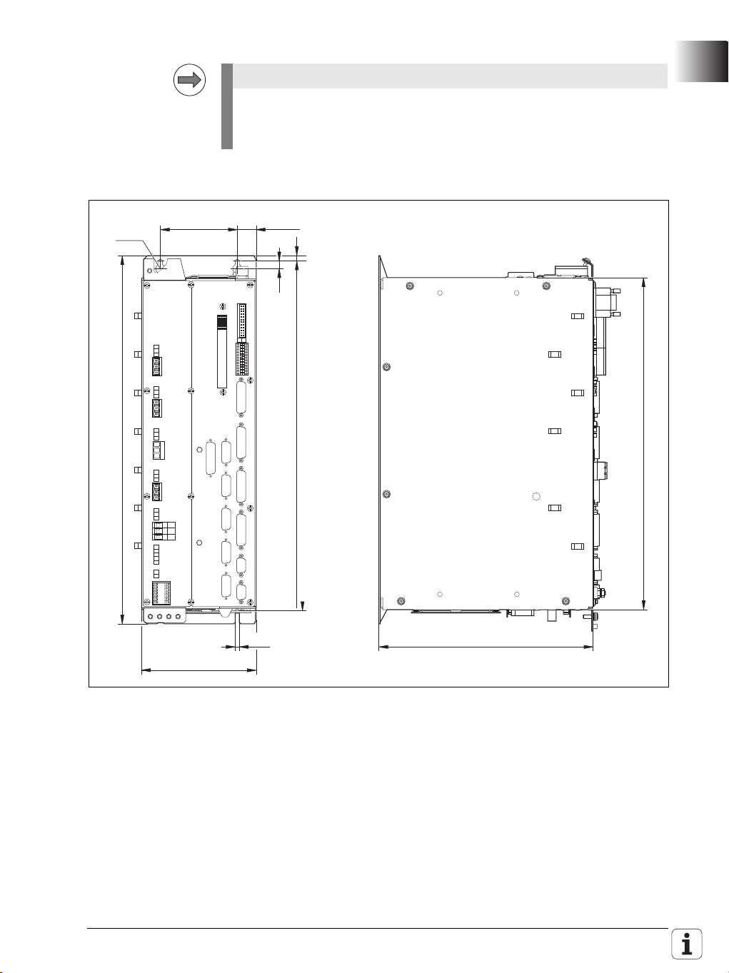
Service
Note
280
433
100±0.2 24.75
10
7
456
480
5.5
149.5
‹ 12
Dimensions
Operation of the new UEC 11x (variant 03) with the CNC PILOT 620 is
supported starting with the initial release of NC software version
688 945-01.
November 2010 1.1 Hardware 45
Page 46

✎
46 HEIDENHAIN Technical Manual MANUALplus 620
Page 47

2 Introduction
Danger
Attention
Note
2.1 Meaning of the Symbols Used in this Manual
Failure to comply with this information could result in most serious or fatal
injuries, and/or in substantial material damage.
Failure to comply with this information could result in injuries and
interruptions of operation, including material damage.
Tips and tricks for operation as well as important information, for example
about standards and regulations as well as for better understanding of the
document.
2.2 Proper Operation
The described components may only be installed and operated as described
in this manual. Commissioning, maintenance, inspection and operation are
only to be performed by trained personnel.
2.3 Trained Personnel
Trained personnel in the sense of this manual means persons who are familiar
with the installation, mounting, commissioning, and operation of the
HEIDENHAIN components. Furthermore, electrical engineering work on the
system may be carried out only by trained electrical engineering technicians or
persons trained specifically for the respective application.
Basically, persons who perform work on HEIDENHAIN components must
meet the following requirements:
They must have been trained or instructed in the standards of safety
They must have appropriate safety equipment (clothing, measuring
They should be skilled in first-aid practice.
engineering.
systems).
November 2010 2.3 Trained Personnel 47
Page 48

2.4 General Information
The HEIDENHAIN MANUALplus 620 contouring control was conceived for
standard CNC lathes. The control has an integrated digital drive control and
drives the power modules through PWM signals.
Integration of the drive controllers in the MANUALplus 620 offers the
following advantages:
All the software is contained centrally in the NC; this means that the
individual components of the NC, such as feed axes, spindle, NC or PLC, are
optimally matched.
High control quality, because the position controller, speed controller and
current controller are combined into one unit.
The same functions are available for commissioning, optimizing and
diagnosing feed drives as well as spindles.
The MANUALplus 620 supports lathes up to the following level:
1 slide (NC channel)
4 axes (X/ Z/ Y and W axis)
2 spindles (main spindle, driven tool)
1 C axis (via main spindle drive or with separate drive)
The following diagram illustrates drive control with the use of a rotary encoder
for measuring the shaft speed actual values and a linear encoder or angle
encoder for measuring the position actual values.
The MANUALplus 620 is based on HEIDENHAIN NCK, the software platform
for the HEIDENHAIN control family. Other controls with NCK are, for example,
the TNC 620, TNC 320 or the CNC PILOT 620.
The MC 6110T, the compact main computer of the MANUALplus 620, takes
up very little space, as it is housed in the operating console, directly behind the
integrated 12.1-inch TFT display.
48 HEIDENHAIN Technical Manual MANUALplus 620
Page 49

The MC is connected to the CC controller unit, the MB machine operating
DATA
DATA
CLOCK
CLOCK
5
5 V
U
N
UP *)
U
N
*)
panel and the PL 6xxx PLC input/output systems via HSCI (HEIDENHAIN
Serial Controller Interface). The connection of the various control components
via HSCI offers numerous benefits, including:
Simple and uncomplicated wiring
High noise immunity
Simple commissioning
Comprehensive yet straightforward possibilities for diagnostics
The MANUALplus 620 is prepared for the connection of incremental and
absolute position and shaft-speed encoders. EnDat 2.2, which is purely digital
and compatible to version 2.1, makes it possible to very rapidly transmit highly
resolved position values over long cable lengths. An overview of EnDat 2.2:
November 2010 2.4 General Information 49
Page 50

Overview of the purely digital control architecture with HSCI and EnDat 2.2:
HSCI PWM
EnDat 2.2
EnDat 2.2
EnDat 2.2
PL
PL
HSCI
HSCI
HSCI
Main
Computer
MC
Controller
Unit
CC
Inverter
Rotary Encoder
Linear Encoder
Rotary Encoder
Drive
The MANUALplus 620 is designed for connection of a compact or modular
inverter system. A complete control package, including drives and
HEIDENHAIN motors, can be delivered (see the "Inverter Systems and
Motors" Technical Manual).
50 HEIDENHAIN Technical Manual MANUALplus 620
Page 51

2.4.1 HSCI interface
The individual control components communicate with each other via the HSCI
connection (HEIDENHAIN Serial Controller Interface). A connection via HSCI
is only permitted for HEIDENHAIN components that are part of the machine
tool's control system. In addition, the HSCI connecting cable may only be
installed in a protected manner (e.g. within the electrical cabinet, cable ducts).
The following features characterize the HSCI connection:
Based on standard 100BaseT Ethernet hardware
Telegrams of the HSCI connection are not compatible with the Ethernet
Line structure
Only one master in the system (MC), all other devices are HSCI slaves
Different addresses are assigned to the individual participants in the HSCI
network. The addresses are assigned dynamically during booting of the MC.
The HSCI addresses of the participants are formed from an HSCI address
(8 bits) and a device type address (6 bits).
After the machine has undergone acceptance testing, the nominal
configuration of the control is saved in the IOC file on the control's memory
card. This nominal configuration contains the assignment of the device-type
address and serial number of the device to the individual HSCI addresses. The
momentary configuration is ascertained during startup of the system by
requesting the serial numbers. The momentary configuration is compared
with the nominal configuration. If there is a deviation, the machine operator is
prompted to check the configuration.
The following applies to the assignment of the HSCI address:
The HSCI address (bus address) is the result of the device's position in the
bus
The master (MC) always has the HSCI address 0.
The HSCI addresses of the slaves result from their position in the bus:
• First device after the master (MC): Bus address 1
• Second device after the master (MC): Bus address 2
•etc.
The device type address is for internally distinguishing between connected
HSCI participants. Each device type (MC, CC, PL, MB, etc.) is assigned a type
specification that is used to address all HSCI participants of this type.
More information on the connection of the HSCI components is provided
under “HSCI" on page 122.
November 2010 2.4 General Information 51
Page 52

2.5 Component Overview of MANUALplus 620
2.5.1 MC main computer, CFR memory card and SIK
The MANUALplus 620 always includes at least the following components:
MC 6110T main computer
(MC = Main Computer)
and either:
CC 61xx controller unit
(CC = Controller Computer)
PL 620x system PL
Modular or compact HEIDENHAIN inverter system
or
UEC 11x controller unit with integrated inverter and PLC
MC 6110T main computer
Compact main computer for
incorporation in the operating
console, with integrated TFT flatpanel display and operating keys.
Machine operating panel is
optional.
Processor:
Intel Celeron M 1.0 GHz
1 GB RAM
HSCI interface
Ethernet interface 100BaseT
3 x USB 2.0
(1 in the operating panel, 2 on
the rear)
1 x RS-232C
MC 6110T ID 731 604-xx
Additionally required:
CFR CompactFlash memory
card
• CompactFlash memory
card, Type 1
• Contains the NC software
• 1 GB memory capacity, of
which 250 MB are for V:\
partition and 50 MB for O:\
partition. Remaining
memory is used for system
data.
52 HEIDENHAIN Technical Manual MANUALplus 620
Page 53

SIK System Identification Key
Note
• Contains the NC software
license for enabling control
loops and software options
• The SIK number provides
the control with a unique
identification.
Main computer components ID
MC 6110T compact main computer 731 604-xx
CompactFlash memory card (CFR)
with MANUALplus 620 software
SIK component, 3 control loops and the "Teach-in," "smart.Turn," "Thread
recutting" and "C-axis machining" software options are enabled, see
“Software options" on page 85.
Control loop expansions: ID
Enabling for:
Addition of a 4th control loop 354 540-01
Addition of a 5th control loop 353 904-01
Addition of a 6th control loop 353 905-01
Addition of a 7th control loop 367 867-01
Further control loops can be enabled in addition to the control loops of the
respective SIK version. The maximum number is:
UEC 111: 4 control loops
UEC 112: 5 control loops
CC 6106: 6 control loops
CC 6108: 7 control loops
733 606-51
733 604-53
Control loop for C axis: If the main spindle drive is used for the C axis,
then one control loop for both the main spindle and the C axis suffices. If
there is a separate drive for the C axis, then the main spindle and C axis
each require their own control loop.
November 2010 2.5 Component Overview of MANUALplus 620 53
Page 54

2.5.2 SIK (System Identification Key)
Note
Each control is clearly identified by the SIK (System Identification Key).
If you replace the MANUALplus 620, you must also replace the SIK in order
to ensure that the enabled options will also be enabled on the new
hardware.
2.5.3 CC 6106 controller unit
CC 610x
Controller unit with HSCI interface for up
to 6 or 8 control loops
It is equipped with:
6 or 8 PWM outputs
6 or 8 speed encoder inputs
6 or 8 position encoder inputs
2 SPI expansion slots
Power supply through UV(R) power
supply unit
CC 6106 ID 598 928-xx
CC 6108 ID 662 637-xx
54 HEIDENHAIN Technical Manual MANUALplus 620
Page 55

2.5.4 UEC 11x controller unit with integrated inverter and PLC
UEC 11x
Controller unit with integrated inverter and
PLC for up to 5 control loops. Compact unit
for machines with limited number of axes
and low power demands.
It is equipped with:
HSCI interface
4 (UEC 111) or 5 (UEC 112) speed
encoder inputs
4 (UEC 111) or 5 (UEC 112) position
encoder inputs
Connection for 3 axes plus spindle
(UEC 111) or
Connection for 4 axes plus spindle
(UEC 112)
Braking resistor
38 PLC inputs, 23 PLC outputs
(expandable via PL 61xx)
Integrated power supply unit 24 V NC /
3.5 A for supplying the HSCI
components
UEC 111 with 4 control loops
ID 625 777-xx
UEC 112 with 5 control loops
ID 625 779-xx
November 2010 2.5 Component Overview of MANUALplus 620 55
Page 56

Designation of the
731 604-01
Variant
Basic ID number
MC 6110T, CC 610x
and UEC 11x
ID of MC 6110T:
The basic ID number indicates hardware differences.
This first digit of the variant number indicates hardware changes.
Variant Changes to MC 6110T
xxx xxx-y1 Initial version
Variant Changes to CC 6106
xxx xxx-y1 Prototype
xxx xxx-y2 Prototype
xxx xxx-y3 Initial version
Variant Changes to CC 6108
xxx xxx-y1 Initial version
Variant Changes to UEC 111
xxx xxx-y1 Prototype
xxx xxx-y2 Initial version
Variant Changes to UEC 112
xxx xxx-y1 Prototype
xxx xxx-y2 Initial version
56 HEIDENHAIN Technical Manual MANUALplus 620
Page 57

2.5.5 PLC input/output systems with HSCI interface
Note
The PLC inputs and outputs of the MANUALplus 620 are available via the
external modular PL 6xxx PLC input/output systems.
The PL 6xxx consists of the PLB 6xxx basic module and one or more I/O
modules. The basic modules are connected to the MC main computer via the
HSCI interface.
The MC 6110T main computer of the MANUALplus 620 does not have
integrated PLC inputs/outputs, and has no connections for TS or TT touch
probes. In order to operate the control, at least the PL 62xx system PL
(when using a CC 610x) or the UEC 11x controller unit with integrated
inverter and PLC is necessary. (The system PL is integrated in the UEC.)
The PLC inputs/outputs components are configured with the PC software
IOconfig.
System PL
PL 62xx
System PL, consisting of PLB 620x basic
module and I/O modules.
One module must be in the HSCI
system if no UEC 11x is used
Available with 4, 6 or 8 slots
HSCI interface
Connections for TS and TT touch probes
Safety-relevant PLC inputs/outputs
For an overview of the available I/O
modules, See "I/O modules" on page 59.
They are mounted on standard NS 35 rails
(DIN 46 227 or EN 50 022)
PLB 6204 ID 591 832-xx
PLB 6206 ID 630 054-xx
PLB 6208 ID 630 055-xx
November 2010 2.5 Component Overview of MANUALplus 620 57
Page 58

Expansion PL
PL 61xx
Expansion PL, consisting of PLB 620x
basic module and I/O modules.
Available with 4, 6 or 8 slots
HSCI interface
Up to 7 PL 61xx can be present in the
HSCI system
For an overview of the available I/O
modules, See "I/O modules" on page 59.
They are mounted on standard NS 35 rails
(DIN 46 227 or EN 50 022)
PLB 6104 ID 591 828-xx
PLB 6106 ID 630 058-xx
PLB 6108 ID 630 059-xx
58 HEIDENHAIN Technical Manual MANUALplus 620
Page 59

I/O modules I/O modules are available with digital and analog inputs and outputs. For
partially occupied PLB basic modules, the unused slots must be occupied by
an empty housing.
PLD-H xx–xx–xx
Digital I/O module:
PLD-H 16-08-00:
I/O module with 16 digital inputs and 8
digital outputs
PLD-H 08-16-00:
I/O module with 8 digital inputs and 16
digital outputs
PLD-H 08-04-00:
I/O module with 8 digital inputs and
4 digital outputs
PLD-H 04-08-00:
I/O module with 4 digital inputs and 8
digital outputs
PLD-H 16-08-00 ID 594 243-xx
PLD-H 08-16-00 ID 650 891-xx
PLD-H 08-04-00 ID 598 905-xx
PLD-H 04-08-00 ID 727 219-xx
November 2010 2.5 Component Overview of MANUALplus 620 59
Page 60

PLA-H xx–xx–xx
Analog I/O module:
PLA-H 04-00-04:
Analog module with 4 analog inputs ± 10
V, 0 analog outputs and 4 inputs for
Pt 100 thermistors.
PLA-H 08-04-04:
Analog module with 8 analog inputs ± 10
V, 4 analog outputs ± 10V and 4 inputs
for Pt 100 thermistors.
PLA-H 04-00-04 ID 599 070-xx
PLA-H 08-04-04 ID 675 572-xx
Empty housing
...for partial assembly
ID 383 022-11
60 HEIDENHAIN Technical Manual MANUALplus 620
Page 61

2.5.6 PSL 130 low-voltage power supply unit
PSL 130
Power pack to supply HSCI components with
+24 V.
The power is supplied via line voltage (L1, L2)
and the DC-link voltage Uz. This is used to
produce the +24-V NC and +24-V PLC output
voltages.
Both output voltages are produced by two
internally separated power supplies. The NC
and PLC power supplies are galvanically
isolated and fulfill the requirements of
EN 61800-5-1 for "low voltage electrical
separation."
Output voltages must be grounded according
to EN 60204-1:2006 "protective extra-low
voltage (PELV)" (see Grounding Diagram).
The two output voltages can be connected in
parallel. This way the PSL 130 provides an
output voltage of +24 V at a maximum output
power of 750 W.
Please observe the information and regulations
for the power connection cited under “PSL 130
low-voltage power supply unit" on page 140 and
in the "Inverter Systems and Motors" Technical
Manual.
ID 575 047-xx
November 2010 2.5 Component Overview of MANUALplus 620 61
Page 62

PSL 135
Power pack for supplying the HSCI components
for use of a non-HEIDENHAIN inverter system.
The power is supplied via line voltage (L1, L2)
and the DC-link voltage U
produce the +24-V NC, +24-V PLC and +5-V
. This is used to
z
output voltages.
+24 V NC and +24 V PLC are produced by two
internally separated power supplies. The NC
and PLC power supplies are galvanically
isolated and fulfill the requirements of
EN 61800-5-1 for "low voltage electrical
separation."
Output voltages must be grounded according
to EN 60204-1:2006 "protective extra-low
voltage (PELV)" (see Grounding Diagram).
+24 V NC and +24 V PLC can be connected in
parallel. This way the PSL 135 provides an
output voltage of +24 V at a maximum output
power of 750 W.
Please observe the information and regulations
for the power connection cited under “PSL 130
low-voltage power supply unit" on page 140 and
in the "Inverter Systems and Motors" Technical
Manual.
ID 627 032-xx
62 HEIDENHAIN Technical Manual MANUALplus 620
Page 63

2.5.7 MB 620T machine operating panel
MB 620T
The MB 620T is equipped with:
HSCI interface
Handwheel connection, X23
Spindle and feed rate override potentiometer
Snap-on (exchangeable) keys, see “Key
symbols" on page 67. The key functions are
freely definable via the PLC
8 PLC inputs and 8 PLC outputs
Two holes for additional keys or keylock
switches
Controls and displays:
9 axis keys
17 function keys
NC start
NC stop
Feed rate stop
Spindle stop
EMERGENCY STOP button
Control voltage On
1)
Key is illuminated
1
ID 737 610-xx
2.5.8 HSCI Adapter for PLB 6001 OEM-Specific Machine Operating Panel
PLB 6001
The PLB 6001 is equipped with:
HSCI interface
Handwheel connection, X23
64 PLC inputs, 32 PLC outputs for
keys / key illumination
Connection for spindle-speed and
feed-rate override potentiometer
Screw fastening or top-hat-rail
mounting
Weight: 1.2 kg
ID 668 792-xx
November 2010 2.5 Component Overview of MANUALplus 620 63
Page 64

2.5.9 Handwheels
All handwheels are available with and without detent. For handwheels with
detent, the cogging torque prevents movements of the handwheel due to
motions or vibrations of the machine. On handwheels without detent, this is
prevented by a defined holding torque.
Handwheels with detent feature 100 detent positions per revolution, i.e. every
3.6°. The machine manufacturer defines the increment via the machine
configuration.
HR 410 handwheel
Portable electronic handwheel with snap-on
(exchangeable) keys, see “Key symbols" on page 67.
Five axis selection keys
Keys for traverse direction
Keys for preset feeds
Actual-position-capture key
Three keys for machine functions
(definable via PLC)
• Spindle right/left/stop
• NC start/stop, spindle start;
(for HEIDENHAIN basic PLC program)
Two permissive buttons (24 V)
Emergency stop button (24 V)
Magnetic holding pads
The handwheel is available with or without detent.
See the following table for the possible handwheel
assignments.
ID 312 879-01Connecting cable to cable adapter (spiral cable 3 m)
ID 296 467-xxConnecting cable to cable adapter (normal cable)
ID 296 687-xxConnecting cable to cable adapter (with metal armor)
ID 296 466-xxAdapter cable to control
ID 281 429-xxExtension to adapter cable
ID 271 958-03Dummy plug for emergency stop circuit
64 HEIDENHAIN Technical Manual MANUALplus 620
Page 65

Key assignments HR 410 handwheel *):
Without detent: Without detent: Without detent:
ID 296 469-55 ID 296 469-54 ID 296 469-53
With detent: With detent:
ID 535 220-05 ID 535 220-03
(for PLC basic program) (special assignment) (standard)
*) For a list of the keys available for exchanging, see “Key symbols" on page 67.
HR 130 handwheel
Panel-mounted handwheel
ID 540 940-01HR 130 handwheel with detent,
with ergonomic control knob, radial cable outlet
ID 540 940-03HR 130 handwheel without
detent, with ergonomic control knob, radial cable
outlet
HR 180 panel-mounted handwheel for
connection to a position input.
ID 540 940-08 Handwheel with mechanical
detent (100 stops per
handwheel revolution), with
ergonomic knob.
Output signal: 1 V
PP
November 2010 2.5 Component Overview of MANUALplus 620 65
Page 66

HRA 110 handwheel adapter
For connecting up to three HR 150 handwheels
to the control.
The axes and the subdivision factor are selected
via selection switch.
ID 261 097-03
HRA 110
ID 540 940-06
ID 540 940-07
ID 270 908-xx
HR 150 handwheel
without detent, with
ergonomic knob, radial
cable outlet
HR 150 handwheel
with detent, with
ergonomic knob, radial
cable outlet
Selection switch
66 HEIDENHAIN Technical Manual MANUALplus 620
Page 67

2.5.10 Key symbols
Key symbols for the
spindle
Key symbols with
axis designations
Key Description
Print/Background
ID
Spindle stop
White/Red
330 816-08
Spindle direction left
Black/Gray
330 816-40
Spindle stop
White/Red
330 816-47
Clamp the spindle
Black/Gray
330 816-48
Key Description
Print/Background
ID
X
Black/Orange
330 816-24
Z
Black/Orange
330 816-25
B
Black/Orange
330 816-26
U
Black/Orange
330 816-43
W
Black/Orange
330 816-45
Key Description
Print/Background
ID
Spindle start
White/Green
330 816-09
Spindle direction right
Black/Gray
330 816-41
Spindle start
White/Green
330 816-46
Key Description
Print/Background
ID
Y
Black/Orange
330 816-36
A
Black/Orange
330 816-42
C
Black/Orange
330 816-23
V
Black/Orange
330 816-38
IV
Black/Orange
330 816-37
Key symbols for
axis direction keys
for the principal
axes
November 2010 2.5 Component Overview of MANUALplus 620 67
Key Description
Print/Background
ID
X–
Black/Gray
330 816-63
X– <–
Black/Gray
330 816-18
Key Description
Print/Background
ID
X+
Black/Gray
330 816-64
X+ –>
Black/Gray
330 816-17
Page 68

Key Description
Y
Print/Background
ID
X'– –>
Black/Gray
330 816-0W
X– <–
Black/Gray
330 816-0N
Y–
Black/Gray
330 816-67
Y'– –>
Black/Gray
330 816-21
Y– <–
Black/Gray
330 816-0P
Y– –>
Y
Black/Gray
330 816-0D
Z–
Black/Gray
330 816-65
Z– <–
Black/Gray
330 816-19
Z'– –>
Black/Gray
330 816-0L
Key Description
Print/Background
ID
X'+ <–
Black/Gray
330 816-0V
X+ –>
Black/Gray
330 816-0M
Y+
Black/Gray
330 816-68
Y'+ <–
Black/Gray
330 816-20
Y+ –>
Black/Gray
330 816-0R
Y+ <–
Black/Gray
330 816-0E
Z+
Black/Gray
330 816-66
Z+ –>
Black/Gray
330 816-16
Z’+ <–
Black/Gray
330 816-0K
Key symbols for
axis direction keys
for rotary and
secondary linear
axes
68 HEIDENHAIN Technical Manual MANUALplus 620
Key Description
Print/Background
ID
A–
Black/Gray
330 816-95
B–
Black/Gray
330 816-97
C–
Black/Gray
330 816-99
U–
Black/Gray
330 816-0B
V–
Black/Gray
330 816-70
Key Description
Print/Background
ID
A+
Black/Gray
330 816-96
B+
Black/Gray
330 816-98
C+
Black/Gray
330 816-0A
U+
Black/Gray
330 816-0C
V+
Black/Gray
330 816-69
Page 69

Key symbols for
machine functions
Key Description
Print/Background
ID
W–
Black/Gray
330 816-0G
IV–
Black/Gray
330 816-71
Key Description
Print/Background
ID
Special function
Black/Gray
330 816-0X
Function B
White/Black
330 816-31
Function 1
Black/Gray
330 816-73
Function 3
Black/Gray
330 816-75
Function 5
Black/Gray
330 816-77
Unlock door
Black/Gray
330 816-79
Coolant (internal)
Black/Gray
330 816-0S
Rinse water jet
Black/Gray
330 816-81
Chip removal
Black/Gray
330 816-83
Tool change
Black/Gray
330 816-89
Tool changer right
Black/Gray
330 816-86
Key Description
Print/Background
ID
W+
Black/Gray
330 816-0H
IV+
Black/Gray
330 816-72
Key Description
Print/Background
ID
Function A
White/Black
330 816-30
Function C
White/Black
330 816-32
Function 2
Black/Gray
330 816-74
Function 4
Black/Gray
330 816-76
Unlock door
Black/Gray
330 816-78
Coolant
Black/Gray
330 816-80
Coolant (external)
Black/Gray
330 816-0T
Spotlight
Black/Gray
330 816-82
Chip conveyor
Black/Gray
330 816-84
Tool changer left
Black/Gray
330 816-85
Unlock tool
Black/Gray
330 816-87
November 2010 2.5 Component Overview of MANUALplus 620 69
Page 70

Other key symbols
Key Description
Print/Background
ID
Unlock tool
Black/Gray
330 816-88
Lock tool
Black/Gray
330 816-0U
Key Description
Print/Background
ID
Lock tool
Black/Gray
330 816-94
Retract axis
Black/Gray
330 816-91
Key Description
Print/Background
ID
No symbol
–/Black
330 816-01
NC start
White/Green
330 816-11
NC start
White/Green
330 816-49
Feed rate 1
Black/Gray
330 816-33
Rapid traverse
Black/Gray
330 816-35
Permissive button
Black/Gray
330 816-90
–
White/Black
330 816-28
Menu selection –>
Black/Gray
330 816-92
0
Black/Gray
330 816-0Y
Key Description
Print/Background
ID
No symbol
–/Gray
330 816-61
NC stop
White/Red
330 816-12
NC stop
White/Red
330 816-50
Feed rate 2
Black/Gray
330 816-34
Permissive button
White/Green
330 816-22
Actual position capture
White/Black
330 816-27
+
White/Black
330 816-29
Menu selection <–
Black/Gray
330 816-93
70 HEIDENHAIN Technical Manual MANUALplus 620
Page 71

2.5.11 Touch probes
Touch probes for workpiece measurement are connected via the system
PL 62xx or the UEC 11x. The touch probes generate a trigger signal that
captures the current position value. For more information about touch probes,
please request the "Touch Probes" brochure or CD-ROM from HEIDENHAIN.
Workpiece
measurement
TS 220 touch probe
Touch trigger probe with cable connection for
signal transmission for machines with manual
tool change. For workpiece setup and
measurement during machining.
ID 293 488-xx
ID 633 613-xx
The TS touch trigger probe has a stylus with which it probes workpieces. The
MANUALplus 620 provides standard routines for workpiece measurement
(software option 17 required). The touch probes are available with various
taper shanks. Assorted styli are available as accessories.
TS 220
Adapter cable for
connection to the
system PL or the UEC
November 2010 2.5 Component Overview of MANUALplus 620 71
Page 72

TS 740, TS 640, TS 444, TS 440 touch probes
TS 640, TS 740 TS 440, TS 444
SE 640 SE 540
Touch trigger probe with infrared transmission,
for workpiece setup and measurement during
machining. For machines with automatic tool
changer.
TS 440 with compact dimensions
TS 444 with alternative battery-free power
supply via compressed air through the spindle
head
TS 640 with wide-range infrared transmission
and long operating time
TS 740 with high probing accuracy and
repeatability, and low probing forces
The infrared transmission is established between
the TS touch probe and the SE transceiver unit.
The following SE units can be combined with the
TS touch probes:
SE 640 for integration in the machine
workspace
SE 540 for integration in the spindle head
ID 573 757-xx
ID 620 189-xx
ID 620 046-xx
ID 588 008-xx
ID 631 225-xx
ID 626 001-xx
TS 740
TS 640
TS 440
TS 444
SE 640
transmitter-receiver
unit
SE 540 transmitter/
receiver unit
72 HEIDENHAIN Technical Manual MANUALplus 620
Page 73

Tool measurement
TT 140 tool touch probe
Triggering touch probe with rated break point of
the connection pin for the probe head and optical
deflection display. An additional connection pin is
delivered with the touch probe.
ID 527 797-03
ID 676 497-01
TT 140
Probe contact, cuboid
ID 559 758-01
ID 633 616-xx
Connection pin
Adapter cable for
connection to the
system PL or the UEC
November 2010 2.5 Component Overview of MANUALplus 620 73
Page 74

2.5.12 Other accessories
2.5.13 Documentation
Further components ID
Adapters for encoder signals
TTL (HEIDENHAIN layout)/1 V
TTL (SIEMENS layout) / 1 V
PP
PP
317 505-01
317 505-02
You will receive a set of supplementary pages every time changes are made
to this manual.
The features of the control are described in the following manuals:
MANUALplus 620 User's Manual (ID 634 864-xx)
MANUALplus 620 / CNC PILOT 620 User's Manual, smart.Turn and DIN
Programming (ID 685 556-xx)
The HEIDENHAIN inverters and motors are described in the
Technical Manual for Inverters and Motors (ID 208 962-xx)
The DataPilot MP/CP 620 is the new programming station for the
MANUALplus 620 and CNC PILOT 620 lathe controls.
DataPilot MP/CP 620 CD-ROM
• Demo software (ID 737 139-xx)
• Single user license (ID 737 157-xx)
• Network license for 14 training stations (ID 737 158-xx)
• Network license for 20 training stations (ID 737 159-xx)
Other
documentation
Available in the form of brochures:
MANUALplus 620 brochure (ID 634 865-xx)
MANUALplus 620 OEM brochure (ID 634 867-xx)
Touch Probes: brochure (ID 208 951-xx)
Inverter Systems brochure (ID 622 420-xx)
Motors brochure (ID 208 893-xx)
Remote Diagnosis with TeleServiceproduct overview (ID 348 236-xx)
Touch Probes CD-ROM (ID 344 353-xx)
74 HEIDENHAIN Technical Manual MANUALplus 620
Page 75

2.6 Brief Description
2.6.1 Specifications of the MANUALplus 620
Specifications MANUALplus 620
MC 6110T
Compact contouring control with integrated main
computer, TFT color flat-panel display and operating keys
Intel Celeron M 1.0 GHz processor
1 GB SDRAM main memory
100 MHz bus frequency
HSCI interface
Three USB interfaces
Unique identification of MC 6110T through SIK (System
Identification Key)
CC 610x
All position and speed encoder inputs 1 V
HSCI interface
Max. 6 or 8 digital control loops
6 or 8 position and 6 or 8 speed encoder inputs with 1
VPP or EnDat 2.2 for axes and spindle
(EnDat 2.2 is backward-compatible to EnDat 2.1)
6 or 8 PWM outputs
Power supply via UV(R), UE or UR power supply unit
UEC 11x
Controller unit with integrated inverter and PLC, for
machines with low power demands
HSCI interface
Controller unit with position, speed and current
controller
UEC 111: Up to 4 digital control loops, connection for 3
axes and spindle
UEC 112: Up to 5 digital control loops, connection for 4
axes and spindle
Integrated braking resistor
38 PLC inputs, 23 PLC outputs (expandable via PL 61xx)
Interfaces to the speed encoders
Interfaces to the position encoders
Interfaces for one TS and TT touch probe each
+24-V NC power supply with 2.5 A for MC and other
control components
or EnDat
PP
November 2010 2.6 Brief Description 75
Page 76

Specifications MANUALplus 620
Axis feedback control
Velocity feedforward control / Operation with following
error / Jerk limiting
Connection of the CC controller unit via HSCI
Cycle time for path interpolation 3 ms
Options
Software options can be enabled by entering a code
number.
Display
12.1-inch TFT color flat-panel display (integrated)
Program memory
250 MB on CFR memory card
Input resolution and display step
Linear axes X axis: 0.5 µm (diameter: 1 µm)
Z Y and W axis: 1 µm
C axis 0,001°
Block processing time
3 ms
Interpolation
Straight line In 2 axes (max. ±100 m), optional in 3 principal axes
Circle In 2 axes (radius max. 999 m), optional additional linear
interpolation in the third axis
C axis Interpolation of X and Z linear axes with the C axis (option)
Helix Superimpositioning of circular and straight paths
Look-ahead Precalculation of up to 5000 blocks for determining the
contouring velocity profile
76 HEIDENHAIN Technical Manual MANUALplus 620
Page 77

Specifications MANUALplus 620
Signal period of position encoder
4096
60000 1/min
No. of pole pairs
• Screw pitch in mm
n
max
f
PWM
60000 min
–1
⋅
p 5000 Hz⋅
------------------------------------------ -=
Regulation with CC 6xxx / UEC 1xx
Position loop resolution
or encoder resolution (EnDat 2.2 interpol.)
Path interpolation 3 ms
Cycle time of current controller PWM frequency Cycle time:
3333 Hz 150 µs
4000 Hz 125 µs
5000 Hz 100 µs
Cycle time of speed controller Speed controller cycle time = 2 · current controller cycle
time
Cycle time of position controller = Cycle time of speed controller
Feed rate Maximum feed rate:
at f
= 5000 Hz
PWM
Up to approx. 32.4 m/min (27 kHz) or approx. 480 m/min
(400 kHz) for encoders with 20 µm grating period
Up to approx. 162 m/min (27 kHz) or approx. 2400 m/
min (400 kHz) for encoders with 100 µm grating period
mm/min or mm/revolution
Constant surface speed
Feed rate with chip breaking
Shaft speed (spindle) Maximum revolutions per minute:
: Maximum spindle speed [min–1]
n
max
f
: PWM frequency [Hz]
PWM
p: Number of pole pairs
The following PWM frequencies are available:
3333 Hz, 4000 Hz, 5000 Hz
November 2010 2.6 Brief Description 77
Page 78

Specifications MANUALplus 620
Thread
Longitudinal thread
Transversal thread (as DIN cycle)
Tapered thread
API thread
Multiple thread
Discontinuous threads with slanted entry and exit
Variable pitch
Tapping
Thread milling (possible only with C axis)
Error compensation
Linear and nonlinear axis error
Backlash
Hysteresis
Reversal error during circular movements
Thermal expansion
Stick-slip friction
Sliding friction
Tool nose (cutting) radius
Milling tool radius
Monitoring functions
Amplitude of encoder signals
Edge separation of encoder signals
Absolute position for encoders with distance-coded
reference marks
Following error
Movement monitoring
Standstill monitoring
Nominal speed value
Checksum of safety-related functions
Power supply
Buffer battery
Operating temperature
Running time of the PLC program
Motor current
Motor temperature
Temperature of power stage
dc-link voltage
78 HEIDENHAIN Technical Manual MANUALplus 620
Page 79

Specifications MANUALplus 620
Integrated PLC
PLC memory 50 MB on CFR memory card
Program format Statement list (STL)
PLC process memory RAM Dynamic, determined by the free main memory of the
control
PLC cycle time 9 ms to 30 ms (adjustable)
PLC inputs, 24 V– Via PL
PLC outputs, 24 V– Via PL
Analog inputs, ±10 V Via PL
Analog outputs, ±10 V Via PL
Inputs for thermistors Via PL
November 2010 2.6 Brief Description 79
Page 80

Machine interfacing MANUALplus 620
Commissioning aids
Oscilloscope
Trace function
Table function
API DATA function
Watchlist function
Logic diagram (integrated in oscilloscope)
Log
OnLine monitor (OLM)
TNCopt PC software
TNCscopeNT recording software
TeleService
Interfaces
100BaseT Fast Ethernet interface
2 x HSCI
3 x USB 2.0
RS-232-C/V.24 with max. 115 Kbps
Expanded interface with LSV-2 protocol for data
exchange and external operation of the control with
HEIDENHAIN software TNCremoNT
Permissible temperature range Incoming air in panel or electrical cabinet
0 to +50 °C
Temperature range outside the panel:
0 °C to +45 °C
Storage: -20 °C to +60 °C
2.6.2 User functions
User functions MANUALplus 620
Operating modes
Manual operation Manual slide movement through manual direction keys,
intermediate switch or electronic handwheels
Graphic support for entering and running cycles without saving
the machining steps in alternation with manual machine
operation
Thread repair (thread reworking in a second workpiece setup)
Teach-In Sequential linking of fixed cycles, where each cycle is run
Program Run Cycle programs, DIN PLUS or smart.Turn programs in single
80 HEIDENHAIN Technical Manual MANUALplus 620
immediately after input or is graphically simulated and
subsequently saved.
block or full sequence
Page 81

User functions MANUALplus 620
Setup functions Workpiece datum setting
Definition of tool-change position
Definition of protection zone
Tool measurement—alternatively:
• By touch-off
• With a touch probe (Option 17)
• With measuring optics (Option 17)
Automatic workpiece measurement (option17)
Programming
Cycle programming Area clearance cycles for simple and complex contours, as well
Interactive contour
programming(ICP)
as contours described with Interactive Contour
Programming (ICP)
Contour-parallel turning cycles
Recessing cycles for simple and complex contours, as well as
contours described with ICP
Repetitions with recessing cycles
Recess turning cycles for simple and complex contours, as well
as contours described with ICP
Undercut and parting cycles
Threading cycles for single or multi-start longitudinal, taper or
API threads
Cycles for axial and radial drilling, pecking and tapping
operations with the C axis
Thread milling with the C axis
Axial and radial milling cycles for slots, figures, single surfaces
and polygons as well as for complex contours defined with ICP
for machining with the C axis
Helical slot milling with the C axis
Linear and circular patterns for drilling and milling operations
with the C axis
Use of DIN macros in cycle programs
Transfer of cutting values from technology database
Context-sensitive help graphics
Conversion of cycle programs to smart.Turn programs
Contour definition with linear and circular contour elements
Immediate display of entered contour elements
Calculation of missing coordinates, intersections, etc.
Graphic display of all solutions for selection by the user if more
than one solution is possible
Chamfers, rounding arcs and undercuts available as form
elements
Input of form elements immediately during contour creation or
by superimposition later
Changes to existing contours can be programmed
November 2010 2.6 Brief Description 81
Page 82

User functions MANUALplus 620
Subfunction of the ICP C-axis machining on face and lateral surface:
Description of individual holes and hole patterns (only with
smart.Turn)
Description of figures and figure patterns for milling operations
(only with smart.Turn)
Creation of freely definable milling contours
Y-axis machining (option 70) in the XY and ZY planes (only with
smart.Turn):
Description of individual holes and hole patterns
Description of figures and figure patterns for milling operations
Creation of freely definable milling contours
DXF import (option 42): Import of contours for lathe and milling
operations
smart.Turn programming Program blocks (UNITS) for the complete description of a
machining block (geometry, technology and cycle data)
Dialog boxes divided into overview and detail forms
Fast navigation between the fillable forms and input groups via
the "smart" keys
Context-sensitive help graphics
Start unit with global settings
Transfer of global values from the start unit
Transfer of cutting values from technology database
Units for all turning and recessing operations for simple
contours and ICP contours
Units for boring, drilling and milling operations with the C and Y
axes for simple holes, milling contours and drilling and milling
patterns or those programmed with ICP
Special units for activating/deactivating the C axis, subprograms
and section repeats
Verification graphics for blank and finished part and for C and Y
axis contours
Turret assignment and other setup information in the
smart.Turn program
Parallel programming
Parallel simulation
82 HEIDENHAIN Technical Manual MANUALplus 620
Page 83

User functions MANUALplus 620
DIN PLUS - Programming NC programming as per DIN 66025 (ISO 6983)
Extended command format (IF...THEN...ELSE...)
Simple geometry programming (calculation of missing data)
Powerful fixed cycles for area clearance, recessing, recess
turning and thread machining
Powerful machining cycles for boring, drilling and milling with
the C axis
Powerful fixed cycles for drilling and milling with the Y axis
(option 70)
Subprograms
Programming with variables
Contour description with ICP
Program verification graphics for workpiece blank and finished
part
Turret assignment and other setup information in the DIN PLUS
program
Conversion of smart.Turn units into DIN PLUS command
sequences
Parallel programming
Parallel simulation
Program verification graphics Graphic simulation of cycle execution for cycle programs,
smart.Turn or DIN PLUS programs:
Display of the tool paths as wire-frame or cutting-path graphics,
special identification of the rapid-traverse paths
Machining simulation (2-D material-removal graphic)
Side or face view, or 2-D view of cylindrical surface for
verification of C-axis machining
Display of programmed contours
View of face and YZ plane for verification of Y-axis machining
Workpiece blank definition
Three-dimensional graphic display of the workpiece blank and
finished part
Shifting and magnifying functions
Machining time analysis Calculation of machining times and idle times
Consideration of switching commands triggered by the CNC
Individual times per cycle or tool change
November 2010 2.6 Brief Description 83
Page 84

User functions MANUALplus 620
Tool database Database for 250 tools with tool description
Option 10: 999 tools
Tool description can be entered for every tool
Automatic inspection of tool-tip position with respect to the
contour
Compensation of tool-tip position in the X/Y/Z plane
High-precision correction via handwheel, capturing
compensation values in the tool table
Automatic tool-tip and cutter radius compensation
Management of multipoint tools (multiple inserts on one tool
holder)
Tool monitoring after rated life of insert or number of
workpieces
Option 10: Tool monitoring with automatic tool change after
tool insert wear
Tool compensation Compensation of tool-tip position in the X/Y/Z plane
Automatic tool point position detection (left, right, inward,
outward)
High-precision adjustment via handwheel, capturing
compensation values in the tool table
Automatic tool-tip and cutter radius compensation
Technology database Access to cutting data after definition of workpiece material,
Conversational languages Chinese (simplified), Chinese (traditional), Czech, Danish, Dutch,
cutting material and machining mode (reduced number of
database entries). The MANUALplus distinguishes between
16machining modes. Each workpiece-material/tool-material
combination includes the cutting speed, the main and
secondary feed rates, and the infeed for 16machining modes.
Automatic determination of the machining modes from the
cycle or the machining unit
The cutting data are entered in the cycle or in the unit as default
values.
9 workpiece-material/tool-material combinations (144 entries)
Option 10: 62 workpiece-material/tool-material combinations
(992 entries)
English, Finnish, French, German, Hungarian, Italian, Polish,
Portuguese, Russian, Spanish, Swedish
Only with option 41 (ID 530 184-xx): Estonian, Korean, Latvian,
Lithuanian, Norwegian, Romanian, Slovak, Slovenian, Turkish
84 HEIDENHAIN Technical Manual MANUALplus 620
Page 85

2.6.3 Software options
Option
number
0 Additional axis 354 540-01 Additional control loops 1, 2 and 3 (additional
1 353 904-01
2 353 905-01
8 Software option 1
9 Software option 2
10 Software option 3
11 Software option 4
17 Touch probe functions 632 230-01 Tool and workpiece measurement
41 Additional languages 530 184-xx Additional conversational language
42 DXF import 632 231-01 DXF import
55 C-axis machining 633 944-01 C-axis machining
70 Y-axis machining 661 881-01 Y-axis machining
94 W-axis machining 679 676-01 W-axis support
Option ID Comment
control loop 3 available on with MC 420)
632 226-01 Cycle programming
Teach-in
632 227-01 smart.Turn
smart.Turn
632 228-01 Tools and technology
Tools and technology
632 229-01 Thread
Thread recutting
Contour description with ICP
Cycle programming
Technology database with 9 workpiece-material/
tool-material combinations
Contour description with ICP
Programming with smart.Turn
Technology database with 9 workpiece-material/
tool-material combinations
Tool database expanded to 999 entries
Technology database expanded to 62 workpiece-
material/tool-material combinations
Tool life monitoring with exchange tools
Thread recutting
Handwheel superimposition during thread cutting
Determining tool-setting dimensions with a touch
probe
Determining tool-setting dimensions with an
optical gauge
Measuring the workpiece with a touch probe
Estonian, Korean, Latvian, Norwegian, Romanian,
Slovak, Slovenian, Turkish,
Lithuanian
Loading of DXF contours
November 2010 2.6 Brief Description 85
Page 86

2.6.4 Accessories
Accessories MANUALplus 620
PL 6xxx PLC input/output
systems with HSCI
Power supply for HSCI
components
Up to eight PL 6xxx can be connected
PL 620x (system PL)
• Necessary once for each control system (except with UEC)
• Has connections for TS and TT touch probes
• Safety-relevant inputs/outputs
• Available for 4, 6 or 8 I/O modules
PL 610x (expansion PL)
• As addition to the system PL for increasing the number of
PLC inputs/outputs
• Available for 4, 6 or 8 I/O modules
I/O modules
• PLD-H 16-08-00
I/O module with 16 digital inputs and 8 digital outputs
• PLD-H 04-00-04
I/O module with 4 analog inputs for PT 100 thermistors and
4 analog inputs for ± 10 V
• PLD-H 00-12-00
I/O module with 12 analog outputs for ± 10 V
PSL 13x
24-V power pack for supplying the HSCI components.
• Outputs:
NC: 24 V– (double isolation)
PLC: 24 V– (basic isolation)
Per output: max. 21 A/ 500 W
Total: Max. 32 A / 750 W
• Outputs can be connected in parallel
Electronic handwheels One HR 130 panel-mounted handwheel or an HR 410 portable
handwheel at the X23 serial input.
Up to three HR 150 at the X23 serial input via HRA 110.
HR 180 panel-mounted handwheels at position inputs. The
number is limited by the number of vacant position inputs. You
can additionally connect an HR 410 serial handwheel, an HR 130
or up to three HR150 (via HRA 110) to X23.
Workpiece touch probe TS220 3-D touch trigger probe with cable connection or
TS 440, TS 444, TS 640 and TS 740 triggering 3-D touch probe
with infrared transmission
Tool touch probe TT 140 with a cuboid probe contact
86 HEIDENHAIN Technical Manual MANUALplus 620
Page 87

Accessories MANUALplus 620
Software PLCdesignNT
a
PLC software developing environment
IOconfig
a
Software for configuring PLC I/O and PROFIBUS-DP
components
TNCremoNT
Data transfer software
TNCremoPlus
Data transfer software with "live" screen
TNCscopeNT
a
Software for recording data online or evaluating oscilloscope
measurement series
DriveDiag
a
Software for diagnosis of digital control loops
TNCopt
a
Software for putting digital control loops into service
KinematicsDesign
a
Software for configuring the machine kinematics
TeleService
Software for remote diagnostics, monitoring, and operation
a. For registered customers, these software products are available for downloading over the
Internet.
November 2010 2.6 Brief Description 87
Page 88

2.7 Software
Attention
Do not make any changes to the operating system, the operating system
settings, or to the software supplied by HEIDENHAIN. Non-HEIDENHAIN
applications may be used only with the permission of HEIDENHAIN.
2.7.1 Designation of the software
The control features a separate software for the NC and the PLC. The NC
software is identified with an eight-digit ID number.
To show the software version:
Switch to the Organization mode of operation.
Press the soft key. The MANUALplus 620 shows the control
model and the versions of the NC and PLC software. An
installed service pack is shown by SPx after the ID number of
the NC software.
Model The MANUALplus 620 is approved for export to all countries. No export
license is required for the NC software of the control.
HEIDENHAIN may release a new NC software type when it introduces
extensive new functions.
88 HEIDENHAIN Technical Manual MANUALplus 620
Page 89

2.7.2 PLC software
The PLC software is stored on the hard disk of the MANUALplus 620.
HEIDENHAIN offers a PLC basic program you can order directly from
HEIDENHAIN. With the PLC development software PLCdesignNT, the PLC
basic program can very easily be adapted to the requirements of the machine.
2.7.3 Enabling additional control loops or software options
In the standard version of the MANUALplus 620 with SIK (ID 530 005-53),
three control loops (2 axes + 1 spindle), the software options with option
numbers #08 "Cycle programming", #09 "smart.Turn", #11 "Threads" and #55
"C axis" are enabled. You can enable up to three further control loops (#00, #01,
#02) as well as the software options with option numbers #10 Tools and
Technology, #17 Tool Measurement, #41 Additional Conversational
Languages, #42 DXF Import, #70 Y-axis Machining and #94 W-axis Support by
entering a code number.
If you wish to enable an additional control loop or software options, please
contact HEIDENHAIN for the code number. HEIDENHAIN can give you the
code number after having been informed of the SIK number.
To enable options, proceed as follows:
Switch to the Organization mode of operation.
Press the soft key. The MANUALplus 620 shows the control
model and the software versions.
Enter the code number SIK and confirm your entry with the ENT key.
The following SIK dialog for the enabling of options appears:
November 2010 2.7 Software 89
Page 90

90 HEIDENHAIN Technical Manual MANUALplus 620
Page 91

Display Meaning
Note
SIK ID SIK number
SIK SN SIK serial number
Control Type Control model
General Key Enter the master code number 65535 to enable all
options for the duration of two weeks.
NONE: Master code number has not been entered yet.
dd.mm.yyyy: Date up to which all options will be
enabled. It is not possible to enable the options again
by entering the master code number.
EXPIRED: The two weeks since the master code
number was entered have expired.
Option column Display of option numbers and brief description of
options that can be enabled.
Active column X: Option is enabled
Keycode column Input field for entering the key code of the option to be
enabled.
This field is gray for options that have already been
enabled.
The Option column shows all options available for the MANUALplus 620.
Enter under Keycode the code number for enabling the option.
Confirm your entry with the ACTIVATE soft key or button. HEIDENHAIN can
give you the code number after having been informed of the SIK number.
The message Option <number> has been set appears.
If the code number is correct, the enabled option is identified by the entry X in
the Active column.
Should you have ordered more than one option, and received more than
one key code from HEIDENHAIN:
You must enable each option individually. It is possible to enter more than
one option in the Keycode column, but then these options cannot be
enabled. In this case the Incorrect password error message always
appears.
It is not possible to enable more than one option simultaneously. Enter the
first key code and then press the ACTIVATE soft key. Then enter the second
key code and press the ACTIVATE soft key again, and so on.
Press the CANCEL soft key or button. To be able to use the option, you first
have to restart the control.
After entry of the master code number (65535), all options are enabled for 14
days. After these 14 days have expired, an error message appears, the
program currently running is aborted, and it is not possible to restart the
program. In order to avoid this error message (and the associated
unintentional program abort), the General Key must be cleared with the CLEAR
soft key. Only the options actually enabled are then available, and the General
Key cannot be entered again.
November 2010 2.7 Software 91
Page 92

Soft keys and
buttons in the SIK
menu
Soft key or
button
Function
The General Key, which enables all options for two weeks,
is disabled.
Jumps back one page in the option list.
Jumps forward one page in the option list.
Activates an option on the control, if the key code has been
entered under Keycode.
Exits the SIK menu. If a software option has been enabled,
the user also has to restart the control.
Overview of the
options
Interrogate options
with PLC module
See “Software options" on page 85.
PLC Module 9067 can be used to interrogate the software options set in the
SIK (see “Module 9067 Status of software settings" on page 676).
92 HEIDENHAIN Technical Manual MANUALplus 620
Page 93

2.7.4 Configurations
C1(S4)
Y1 Z1
The configuration of the MANUALplus 620 is designed for one slide (with X,
Z, Y and W axes), spindle, C axis and driven tool. Use parameters to hide
components not present on the machine. You also set the type of C-axis drive
(separate C-axis drive or driven with spindle motor) via parameter. If there is a
separate drive for the C axis, an additional control loop is required.
Please contact HEIDENHAIN if you require a different configuration.
Configuration of the MANUALplus 620
Machine setup Axes and spindles
2 spindles (spindle and driven
tool)
1 slide
2 linear axes (X and Z axes)
1 C axis (drive with spindle motor)
Maximum expansion (6 control
loops)
2 spindles (spindle and driven
tool)
1 slide
3 linear axes (X, Z and Y axes)
1 C axis (drive with separate
motor)
Maximum expansion (7 control
loops)
2 spindles (spindle and driven
tool)
1 slide
4 linear axes (X, Z, Y and W axes)
1 C axis (drive with separate
motor)
2.7.5 Coordinate system of the lathe
You specify the coordinate system of the lathe in the kinematics description.
The parameter MP_CoordSystem (in System/DisplaySettings/
CfgCoordSystem) is relevant for the simulation, graphic representation in ICP
and for the help graphics. The following settings are possible:
+X / +Z: Horizontal lathe—turning behind the center
–X / +Z: Horizontal lathe—turning in front of center
+Z / +X: Vertical lathe—turning to the right of center
November 2010 2.7 Software 93
Page 94

2.7.6 NC software exchange on the MANUALplus 620
Note
Note
Note
The NC software must be exchanged only by trained personnel.
To enable the user to exchange the NC software, HEIDENHAIN provides
a packed file with the NC software. For intermediate storage, the packed
file is stored on a USB memory stick or a USB hard disk. Then it is
installed on the control from the intermediate storage medium.
HEIDENHAIN recommends making a backup of the control, for example
with TNCbackup (included in TNCremoNT), before updating the NC
software, See "Data backup" on page 106.
General
information
The setup.zip file is required for the software exchange. The installation
program of the control automatically detects the file, which must be stored
in the root directory of the data medium from which the update is run.
HEIDENHAIN recommends:
Use a USB memory stick (1 GB or larger) to exchange the software. Do not
use any memory stick with a smaller storage capacity.
A backup of the control's most recent NC software is automatically created,
while the software is being updated. The backup file is packed and stored
on the memory stick. If the update is not completed successfully, your
previous NC software version will automatically be restored. In addition, the
complete update archive is automatically unpacked to the memory stick
before installation. The memory stick must have enough free space for the
backup and for unpacking the setup files. This is ensured by using a USB
memory stick with a storage capacity of 1 GB.
As a registered customer, you will receive the setup.zip file necessary for
the update directly from HEIDENHAIN.
To do so, please write by e-mail to filebaseteam@heidenhain.de.
Software updates and installation from service packs are loaded in the same
manner.
The NC software has been prepared in such a manner that when an update
is performed or a service pack loaded, the PLC program, the machine
configuration or data on the PLC partition can be updated as well, according
to the OEM's specific requirements. The OEM uses the HEIDENHAIN PC
software PLCdesignNT to add all necessary files to the setup.zip archive.
These files are copied to the appropriate locations on the control during an
update.
94 HEIDENHAIN Technical Manual MANUALplus 620
Page 95

Note
For detailed information on how to add OEM specific files to the setup
packet, refer to the online help for PLCdesignNT under "Generate Machine
Setup." The support necessary for this from PLCdesignNT will be available
starting from version 2.5.
Procedure for
exchanging the NC
software
To install an NC software update, proceed as follows:
If the machine is running, shut down the control by pressing the OFF soft
key.
Switch off the machine.
If the new NC software is stored on a USB memory stick or a USB hard disk,
connect the storage medium to a free USB socket (X141 or X142) on the
MC 420.
Switch the machine back on again.
When the screen turns blue while the control is starting up, press the DEL
key on the operating panel repeatedly. You must not hold down the DEL
key. The control interrupts the boot process and a login message of the
HEIDENHAIN operating system will be displayed:
Enter 049866931 or 1 for "User name." If a USB keyboard is connected to
the control, you can also enter update as an alternative.
Press the ENT key or the RETURN key on the external USB keyboard.
November 2010 2.7 Software 95
Page 96

The control starts the HE menu. The following window appears on the
screen:
Select the Update menu item and confirm your entry with the ENT key.
Select the source on which the packed files for the software update are
stored. If the setup files are stored on a USB stick, select
Source: USB stick. Press the ENT key to confirm your selection.
96 HEIDENHAIN Technical Manual MANUALplus 620
Page 97

The control then starts the boot updater. A new window opens, which
displays the contents of the update packet:
Select 1 and confirm your selection with the ENT key.
The control automatically performs the NC software update (approx. 20 to
30 minutes).
After the update has been completed, the control requests you to remove
the USB memory stick and then press ENT:
Remove the USB stick and then press ENT or Return!
Remove the USB device (memory stick or hard disk) from the control.
Press the ENT key or the RETURN key on the optional USB keyboard.
The control is shut down and then restarts automatically.
The NC software update is complete.
November 2010 2.7 Software 97
Page 98

Start update while
Note
software is running
on the control
As of SW version 548 328-02 you can update the NC software even while it is
running on the control.
Please note that the space on the CFR memory card is not sufficient for the
MANUALplus 620 to open the Setup.zip file from the "TNC:" or "PLC:" drive.
Always save the file on a USB memory stick with at least 512 MB free
memory.
Plug the memory stick in a free USB socket if the control and start the
update as described below.
Switch to the Organization operating mode
Press the soft key.
Enter the code number 231019.
Press the UPDATE DATA soft key.
Then press the LOAD ZIP soft key
Press the PATH soft key to select the directory, in which the setup file is
located, in the left window.
98 HEIDENHAIN Technical Manual MANUALplus 620
Page 99

Then press the FILES soft key to place the cursor in the right window on file
level. Use the SELECT soft key to select the "setup.zip" file. The
MANUALplus checks whether the selected setup file can be used for the
current software version of the control.
Confirm the confirmation request "Do you really want to switch off?". The
NC software is now automatically shut down and then the actual update
program is started.
Select a dialog language.
The next dialog field shows the old and new software. Confirm the
confirmation request "Do you really want to install the software now?".
Now the software update is started. The bar diagram displays the current
progress of installation.
After the software update is complete you will be prompted to restart the
control. If you have used a USB stick, remove it before restarting the control.
While the control is running up the dialog window for entering the code
number appears. Enter here 95148.
In the next step you are prompted to check the update rules. Press the
UPDATE RULES soft key.
To leave the update rules, press the END soft key.
In the next step, check the configuration data by pressing the CONFIG DATA
soft key.
If parameters were changed, added or removed in the configuration data by
the software update, this is marked by a red exclamation mark. Check all
changed passages of the configuration data and press the SAVE soft key.
Exit the software update by twice pressing the ENDE soft key, and after
booting the control, conduct a restart.
To finally conclude the software update, you have to confirm in a dialog
window any changes of the firmware/hardware of the control; See
"Monitoring hardware changes" on page 106.
November 2010 2.7 Software 99
Page 100

2.7.7 Installing a service pack
Attention
Attention
Note
When needed, HEIDENHAIN prepares service packs for the various
versions of the NC software. To do so, please write as registered customer
by e-mail to filebaseteam@heidenhain.de. Installation of a service pack in
addition to the already installed NC software implements important error
fixes. Please ensure that the NC software always contains the latest
service pack before you ship the machine. Perform all tests required of the
machine or the NC software again after having installed the service pack.
The latest service pack always includes all changes from earlier service packs.
When the control is started, a note regarding the installed service pack is
shown.
HEIDENHAIN recommends always installing the latest released service pack!
If a service pack has already been installed, it will not be possible to install
a service pack with a lower index. This will be checked during the
installation of a service pack and a message will be displayed if an error is
found.
Installing a service
pack
As a registered customer, you will receive the file necessary for the
service pack directly from HEIDENHAIN. The file name consists of the
NC software number and the number of the service pack, e.g.
54832801sp1.zip. To do so, please write by e-mail to
filebaseteam@heidenhain.de.
A service pack must be installed only by trained personnel.
The service pack consists of a packed file (setup.zip). For intermediate
storage, the packed file is stored on a USB memory stick, for example. Then
it is installed on the control from the intermediate storage medium.
A service pack is installed in the same manner as the NC software update. For
instructions, please refer to “Procedure for exchanging the NC software" on
page 95.
100 HEIDENHAIN Technical Manual MANUALplus 620
 Loading...