


HSU09VHJDBW
Installation Manual of Room Air Conditioner
Preparation
Necessary Tools for Installation
Torque wrench
Hammerƽ
Nipperƽ
Hacksawƽ Pipe cutterƽ
Hole core drillƽ Flaring toolƽ
Spanner(17,19 and 26mm)ƽ Knifeƽ
Gas leakage detector orƽ
soap-and-water solution
ƽ
(17mm,2 2mm, 26m m)
Measuring tapeƽ
Reamerƽ
Power Source
ƽ
Before inserting power plug into receptacle, check the voltage without fail.
The power
Install an exclusive branch circuit of the power.
ƽ
Areceptacleshallbesetupin a distancewherethepowercablecanbe
ƽ
reached.
source is the same as the
Donotextendthecablebycuttingit.
correspondingnameplate.
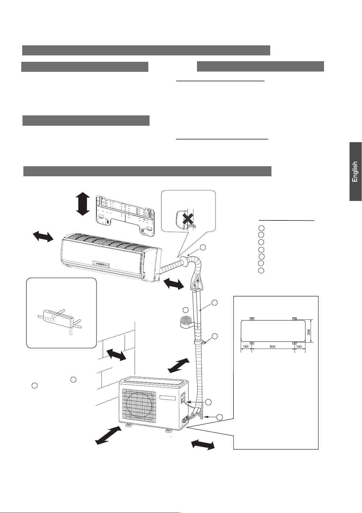
Drawing for the installation of indoor and outdoor units
The models adopt HCFC free refrigerant R410A
more than 5cm
more than
10cm
Selection of Installation Place
Indoor Unit - Select a plocation that is
Robust not causing vibration, where the body can be supported sufficiently.
ƽ
Not affected by heat or steam generated in the vicinity, where inlet and outlet of the
ƽ
unit are not disturbed.
Possible to drain easily, where piping can be connected with the outdoor unit.
ƽ
Where cold air can be spread in a room evenly.
ƽ
Nearby a power receptacle. (Refer to drawings).
ƽ
Place where the distance of more than lm from televisions, radios, wireless apparatuses
ƽ
and fluorescent lamps can be left.
In the case of fixing the remote controller on a wall, place where the indoor unit can
ƽ
receive signals when the fluorescent
Outdoor Unit - Select a plocation that is
Not less affected by rain or direct sunlight and is sufficiently ventilated.
ƽ
ƽ
Strong enough to bear the unit, where vibration and noise are not increased.
Place, where discharged wind and noise do not cause a nuisance to the neighbors.ƽ
Place, where a distance markedƽ
Attention must be paid to
the rising up of drain hose
G
lampsintheroomarelightened.
is available as illustrated in the above figure.
Optional parts for piping
Non-adhesive tape
A
Adhesive tape
B
Saddle(L.S)withscrews
C
Connecting electric cable
D
for indoor and outdoor
E
Drain hose
F
Heating insulating material
Piping hole cover
G
Arrangement of piping
directions
Rear left
Left
Below
The marks from to
ƽ
G
in the figure are the
parts numbers.
Thedistancebetween
ƽ
the indoor unit and the
floor should be more
than 2m.
Rear
right
Right
A
more than
more than 10cm
60cm
more than 10cm
A
more than
10cm
more than15cm
F
C
Floor fixing dimensions of the
outdoor unit (Unit:mm)
Fixing of outdoor unit
Fix the unit to concrete or blockƽ
with bolts (10mm) and nuts firmly
and horizontally.
ƽ
When fitting the unit to wall
D
E
surface, roof or rooftop, fix
a supporter securely with nails
or wires in consideration of
earthquakeandstrongwind.
ƽ
If vibration may affect the
house, fix the unit by attaching a
vibration-proof mat.
The above picture is for your reference only. Your product may look different.
Read this manual before installation.
Explain the operation or the unit to the user according to this manual.
NO.0010526879

Accessory parts
Remote controller (1)
R-03 dry battery (2)
Mounting plate (1)
Plastic cap (4)
Ø4X25 Screw
(4)
Drainhose(1)
Cushion (4)
Drain-elbow (1)
Pipe supporting plate (1)
Selection of pipe
For 12
Liquid pipe (Ø)
Gas pipe (Ø)
NOTE˖Thethickness of thepipemustbe0.8mm at least.
6.35mm(1/4”)
9.52mm(3/8”)
For 18
6.35mm(1/4”)
12.7mm
(1/2”)
Indoor unit
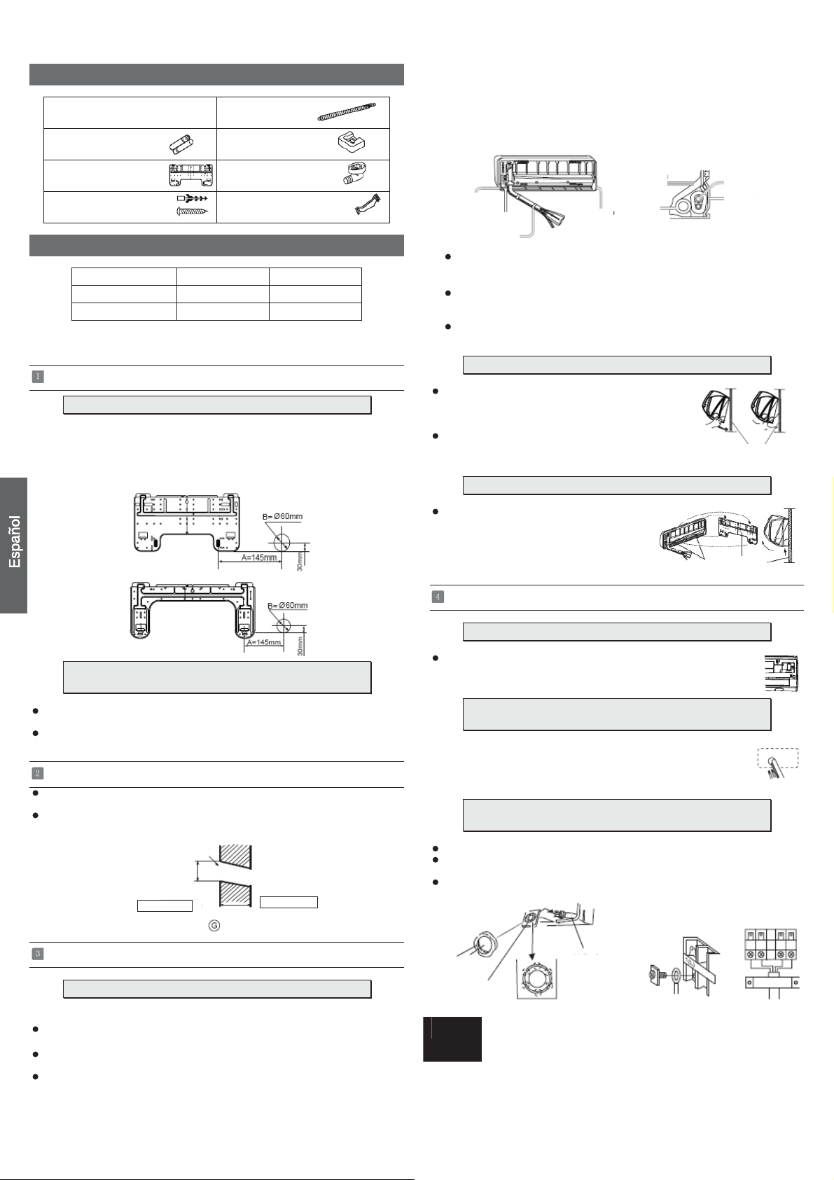
FittingoftheMountingPlateand
When the mounting plate is first fixed
1. Carry out, based on the neighboring pillars or lintels, a
to be fixed against the wall, then
2. Make sure once more the proper level of the plate, by
weight from the central top of the plate, then fasten securely the plate with the
attachment steel nail.
3. Find the wall hole location A using a measuring tape
temporarily fasten the plate with one steel nail.
Positioning of the wall Hole
proper leveling for the plate
hanging a thread with a
1. Insert the drain hose into the dent of heat insulation
2. Insert the indoor/outdoor electric cable from backside of
out on the front side, then connect them.
3.Coattheflaringsealfacewithrefrigerantoilandconnect
Cover the connection part with heat insulation materials, cover with adhesive tape.
Lid for right
piping
Lid for under piping pipe
Fixwithadhesivetape
ƽ
Indoor/outdoorelectriccableanddrainhosemustbeboundwithrefrigerant
piping with protecting tape.
Lid for left piping
materials of indoor unit.
Heat insulation
material
Drain hose
indoor unit, and pull it
pipes.
Indoor/outdoor electric cable
Piping
Pipe supporting
plate
[ Other direction piping ]
ƽ
Cut away, with a nipper, the lid for piping according to the piping direction and
then bend the pipe according to the position of wall hole. When bending, be
careful not to crash
ƽ
Connect beforehand the indoor/outdoor electric cable,
connected to the heat insulation of connecting part specially.
pipes.
andthenpulloutthe
Fixingtheindoorunitbody
Hang the unit body securely onto the upper notches of the
ƽ
mounting plate. Move the body from side to side to verify
its secure fixing.
In order to fix the body onto the mounting plate,hold up
ƽ
thebodyaslantfromtheundersideandthenputitdown
perpendicularly.
mounting plate
Ø
60mm
B=
A=145mm
30mm
Ø
60mm
B=
A=145mm
30mm
When the mounting plate is fixed side bar and lintel
Fix to side bar and lintel a mounting bar, Which is separately sold, and then
ƽ
fasten the plate to the fixed mounting bar.
Refer to the previous article, “ When the mounting plate is
ƽ
position of wall hole.
Making a Hole on the Wall and Fitting the Piping Hole Cover
Make a hole of 60 mm in diameter, slightly descending to outside the wall.
ƽ
Installpipingholecoverandsealit offwithputty afterinstallation
ƽ
Wall hole
Ø60mm
Indoor side
(Section of wall hole) Piping hole pipe
Installation of the Indoor Unit
Thickness of wall
G
Outdoor side
first fixed “, for the
Unloading of indoor unit body
When you unload the indoor unit, please use
ƽ
your hand to raise the body, then lift the
bottom of the body outward slightly
and lift the unit until it leaves the
mounting plate.
mounting plate
agraffe
Connecting the indoor/outdoor Electric Cable
Removing the wiring cover
Remove terminal cover at right bottom corner of indoor unit, then takeƽ
offwiringcoverbyremovingitsscrews.
When connecting the cable after installing the indoor unit
1. Insert from outside the room cable into left side of the wall
hole,inwhichthepipehasalreadyexisted.
2. Pull out the cable on the front side, and connect the cable
making a loop.
When connecting the cable before installing the indoor unit
Insert the cord from the back side of the unit, then pull it out on the front side.
ƽ
Fasten the unit wire harness to the conduit holder using the lock nut.
ƽ
Position the conduit holder to its original state using screw.
ƽ
Drawing of pipe
[ Rear piping ]
Drawpipesandthedrainhose,thenfastenthemwiththeadhesivetape
ƽ
[Left・Left-rear piping ]
ƽ
In case of left side piping, cut away, with a nipper, the lid for left piping.
In case of left-rear piping, bend the pipes according to the piping direction to
ƽ
the mark of hole for left-rear piping which is marked on heat insulation materials.
2
Conduit holder
When connecting the cable, confirm the terminal number of indoor and
Note
outdoor units carefully. If wiring is not correct, proper operation can not
be carried out and will cause defect.
Cut the 6 slit sear
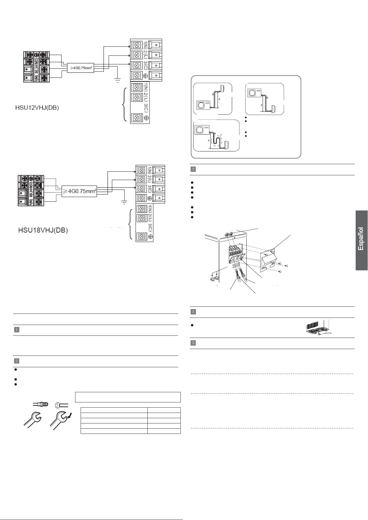
Indoor unit
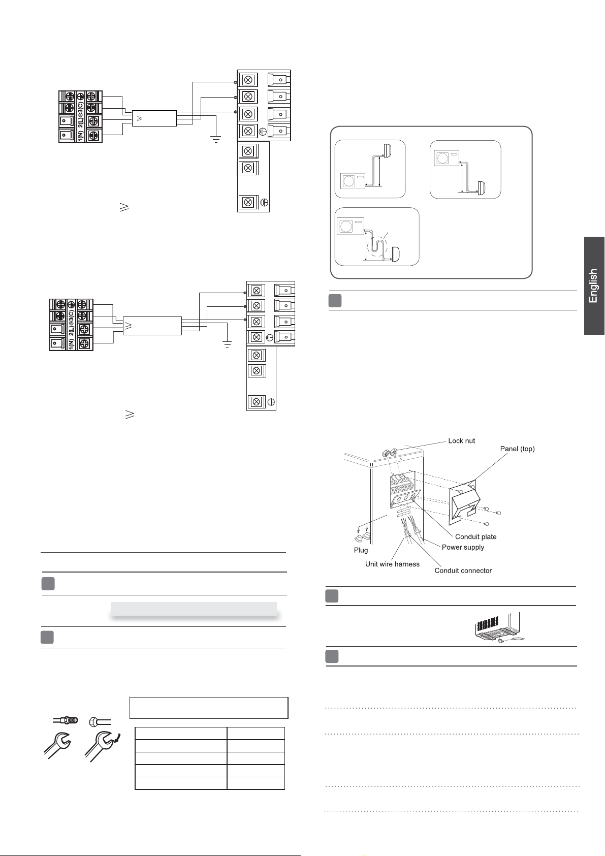
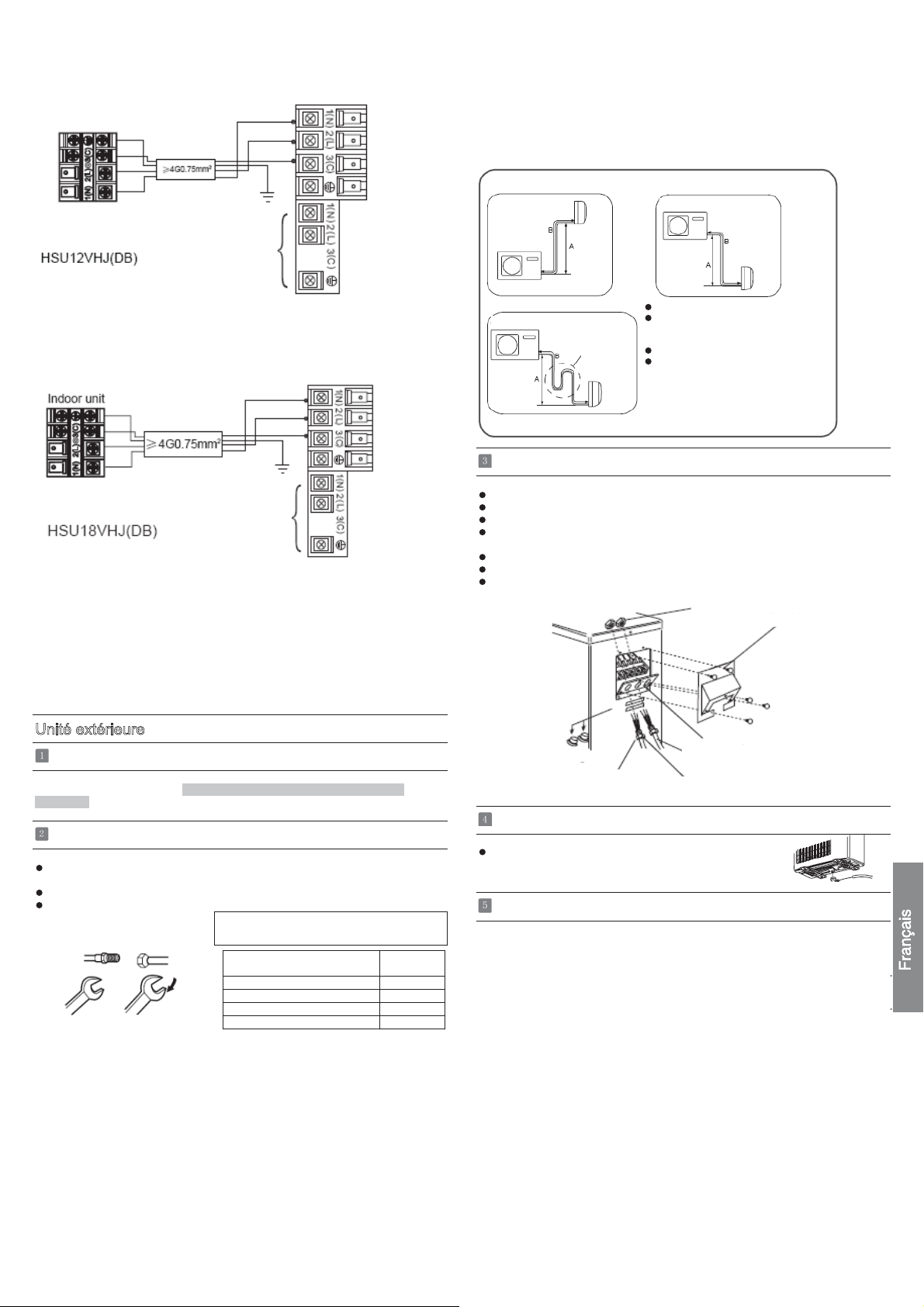
HSU12VHJ(DB)
Power cable:
Indoor unit
HSU18VHJ(DB)
Power cable:
2
4G0.75mm
3G1.5mm
4G0.75mm
2
3G2.5mm
POWER
2
POWER
2
Outdoor unit
^
^
1
(
N
)
2
(
L
)
3
(
C
)
1
(
N
)
2
(
L
)
3
(
C
)
Outdoor unit A
1
(
N
)
2
(
L
)
3
(
C
)
1
(
N
)
2
(
L
)
3
(
C
)
Ensure that on dirt or debris enters the pipe.
Thestandardpipelengthis5m.Ifitisover7m,thefunctionoftheunitwillbe
affected.Ifthepipehas
accordingto20g/m.Butthechargeofrefrigerantmust
sionalairconditionerengineer.Beforeaddingadditionalrefrigerant,performair
purgingfromtherefrigerantpipesandindoorunitusing a vacuum
charge additional refrigerant.
CAUTION
B
Outdoor unit
Outdoor unit
B
A
Connection
ƽ
Take off the panel(top), by removing the 5 screws.
Remove the plugs on the conduit plate.
ƽ
Temporarily mount the conduit tubes on the conduit plate.
ƽ
Connect both the power supply and unit wire harness to
ƽ
to be lengthened, the refrigerant should be charged,
Outdoor unit
Indoor unit
A
Oil trap
Indoor unit
●
●
B
A
Max.Elevation: Amax=1m
In case the elevation A is more●
than 5m, oil trap shoud be
installed every 5~7m
Max. Length: Bmax=5m
In case the pipe length B is●
more than 10m, the refrigerant
should be charged, according
to 20 g/m.
be conducted by profes-
Indoor unit
pump,then
the corresponding terminals on the terminal board.
Ground the unit in accordance with local codes.
ƽ
Allow several extra inches of wire for making wiring
ƽ
connections.
ƽ
Use lock nuts to secure conduit tubes.
1. If the supply cord is damaged, it must be replaced by the manufacturer or its
service agent or a similar qualified person. The type of connecting wire is
H05RN-F
2.IfthefuseonPCboardisbrokenpleasechangeitwiththe
3.Thewiringmethodshouldbeinlinewiththelocalwiringstandard.
4. After installation, the power plug should be easily reached.
5. A breaker should be incorporated into fixed wiring. The breaker should be
or H07RN-F.
T. 3.1 5A /2 50V.
all-pole
switchandthedistancebetweenitstwocontactsshouldbenotless
than 3mm.
type of
Outdoor unit
Installation of Outdoor Unit
Install according to Drawing for the installation of indoor and
Connection of pipes
To bend a pipe, be careful not to crush the pipe,
ƽ
andthebendingradiusshouldbe30to40
ƽ
Connecting the pipe of gas side first makes working easier.
TheconnectionpipeisspecializedforR410A.ƽ
Half union
Spanner
Flare nut
Torque wrench
Forced fastening without careful centering may
damage the threads and cause a leakage of gas.
Liquid side6.35mm(1/4") 18N.m
Liquid/Gas side9.52mm(3/8") 42 N.m
Gas side 12.7mm(1/2") 55N.m
Gas side 15.88mm(5/8") 60 N.m
mm or longer.
Pipe Diameter(ǿ) Fastening torque
outdoor units
Attaching Drain-Elbow
If the drain-elbow is used,ƽ
please attach it as figure. (Note:
Only for heat pump unit.)
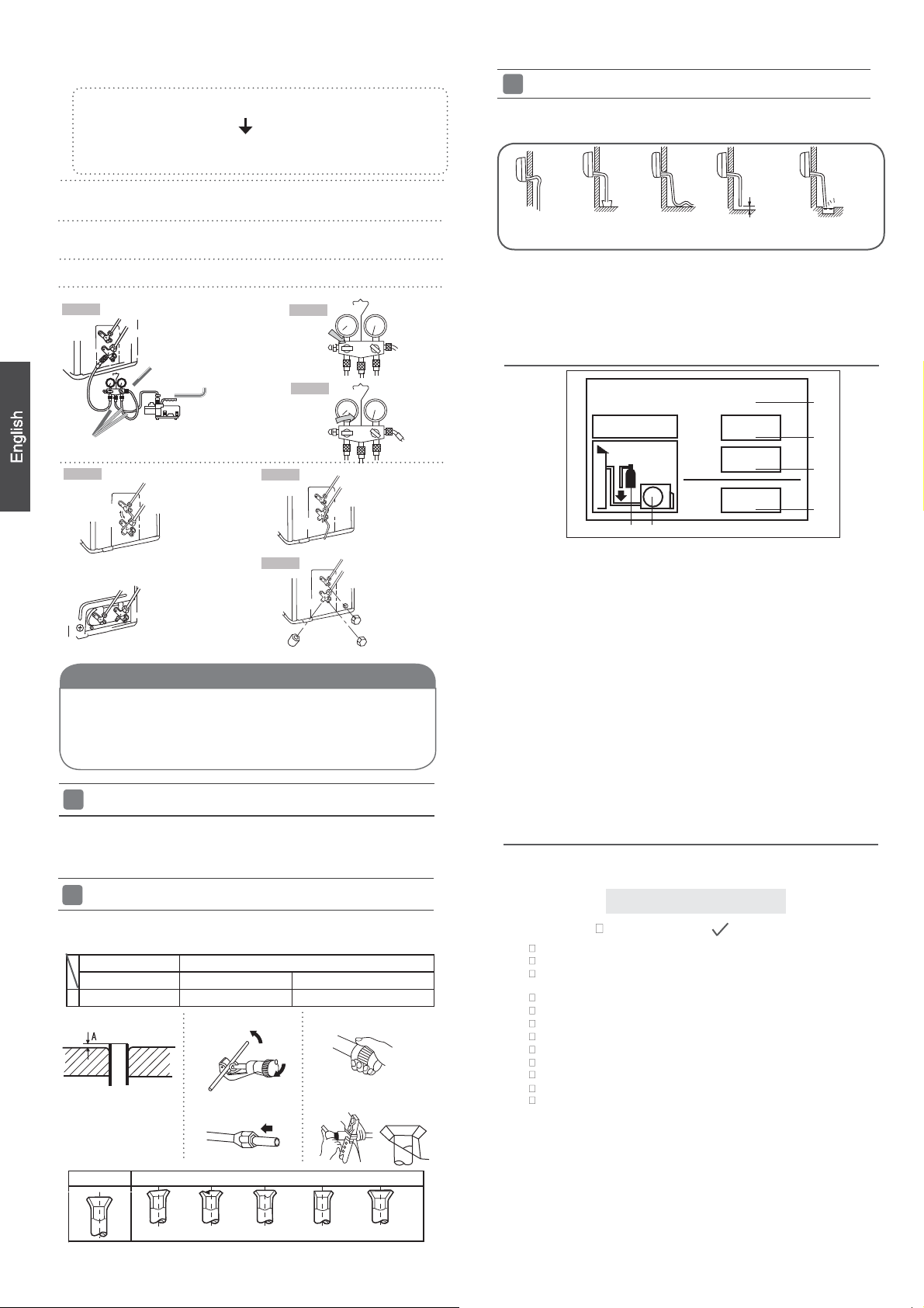
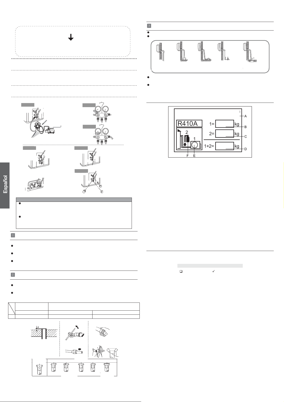
PurgingMethod:Tousevacuumpump
1.
Detach the service port’s cap of
and3-way’s,connecttheserviceportintothe
for gaugemanifold.
gemanifold into vacuum pump.
Open the handle at Iow in
2.
moves of gause (Iow) reach vacuum condition in a moment, check 1. again.
Vacuum for over 15min. And check the gauge which should read -0.1MPa
3.
(76 cm Hg) at Iow
handle ‘Lo’ in gaugemanifold and stop the operation of the vacuum pump. Check
condition of the scale and hold it for 1-2min. If the scale-moves back in spite of
tightening, make flaring work again, the return to the beginning of 3 .
Open the valve rod for the 2-way valve counterclockwise to 90 degrees.4.
After 6 seconds, close the
Then connect the projection of charge hose (center) for gau-
pressure side. After the
3-wayvalve,thevalverod’scapfor2-wayvalve
gaugemanifold, operate vacuum pump. If the scale-
2-way valve and make the
projection of charge hose (Iow)
completion of vacuuming, close the
inspection of gas leakage.
3
No gas leakage?5.
In case of gas leakage, tighten parts of pipe connection. If
leakage stops, then proceed 6. steps
If it does not stop gas leakage, discharge whole refrigerants
port.Afterflaring workagainandvacuumize,fillupprescribed
Detach the charge hose6.
the valve rod counterclockwise.
To prevent the gas
7.
valve and 3-way’s a little more
After attaching the each
8.
Step 1.
Tub e(f or R41 0A)
Step 4.
Open 90
2-way valve
2-way valve Liquid Side
3-way valve Gas Side
2-way valve
3-way valve
O
3-way valve
refrigerant from the gas cylinder.
from the service port, open 2-way valve and 3-way. Turn
leakage, turn the service
than the point where the torque increases sudden
caps, check the gas
Gaugemanifold(for
Anti countercurrent joint
Vacuum pump(for R410A)
port’s cap, the valve
leakagearoundthecaps.
Step 2.
Open
R410A)
Step 3.
Step 6.
Step 7.
Service port cap
Close
from the service
rod’s cap for 2-w
2-way valve
3-way valve
2-way valve
3-way valve
Valve rod cap
Valve rod cap
CAUTION
ƽ
Iftherefrigerant of theairconditionerleaks,itisnecessarytodischargeallthe
refrigerant. Vacuum first, then
accordingtotheamountmarkedonthenameplate.
ƽ
Please do not let other cooling medium, except specified one (R410A), or air
enter into the cooling circulation system. Otherwise, there will be abnormal
highpressureinthesystemtomakeitcrackandleadtopersonalinjuries.
Power Source Installation
ƽ
The power source must be exclusively used for air
ƽ
In the case of installing an air conditioner in a moist place,
rth leakage breaker.
ƽ
For installation in other places, use a circuit breaker as far
Cutting and Flaring Work of Piping
ƽ
Pipe cutting is carried out with a pipe cutter and burs must
ƽ
Afterinsertingtheflarenut,flaring workiscarriedout.
FlaretoolforR410A Conventionalflaretool
Clutch-type clutch-type(Rigid-type) Wing-nut type (Imperial-type)
A 0~ 0.5mm 1.0~1.5mm 1.5~2.0mm
Flare tooling die
charge the liquid refrigerant into air conditioner
conditioner. (Over I0A)
pleaseinstallanea-
as possible.
be removed.
1.Cut pipe
3.Insert the flare nut
2.Remove burs
4.Flare pipe
On Drainage
Pleaseinstallthedrainhosesoastobedownwardslopewithoutfail.
ƽ
Please don’t do the drainage as shown below.
ƽ
Less than
5cm
ay
l
y.
It becomes
high midway.
Please pour water in the drain pan of the indoor unit, and
ƽ
is carried out surely to outdoor.
In case that the attached drain hose is in a room, please
ƽ
it without fail.
The end is immersedinwater.
It waves.
The gap with the
ground is too small
confirm that drainage
applyheatinsulationto
There is the bad
smell from a ditch
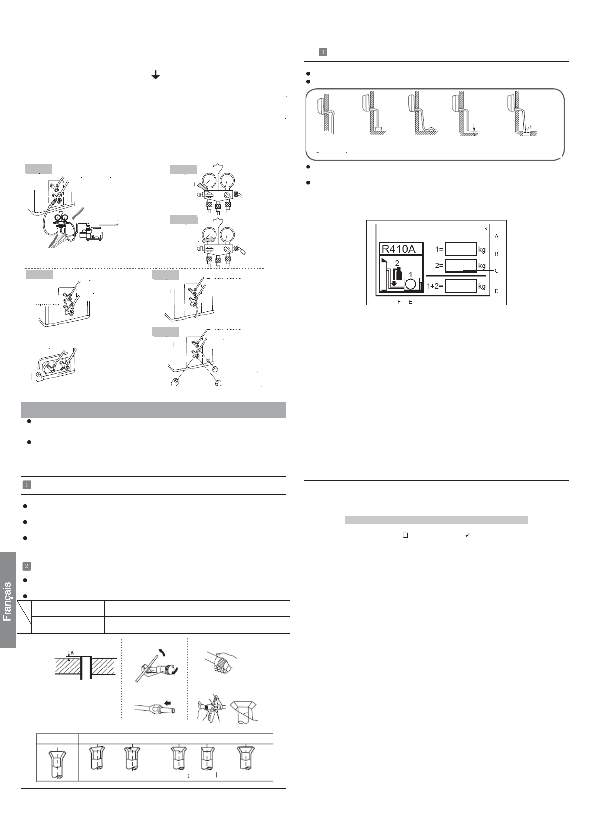
Refrigerant charge labelƵ
Contains fluorinated greenhouse gases
covered by the Kyoto Protocol
R410A
2
1=
2=
1
1+2=
FE
kg
kg
kg
A
B
C
D
This product contains fluorinated greenhouse gases covered by
the Kyoto Protocol. Do not vent into the atmosphere.
Refrigerant type:R410A
GWP* value:1975
GWP=global warming potential
Please fill in with indelible ink,
• 1 the factory refrigerant charge of the product
• 2 the additional refrigerant amount charged in the field and
• 1+2 the total refrigerant charge
on the refrigerant charge label supplied with the product.
The filled out label must be adhered in the proximity of the product
charging port (e.g. onto the inside of the stop value cover).
A contains fluorinated greenhouse gases covered by the Kyoto
Protocol
B factory refrigerant charge of the product: see unit name plate
C additional refrigerant amount charged in the field
D total refrigerant charge
E outdoor unit
F refrigerant cylinder and manifold for charging
Check for Installation and Test Run
Ƶ
Please kindly explain to our customers how to operate
Ƶ
through the instruction manual.
Check Items for Test Run
Put check mark
Gasleakfrompipeconnecting?
Heat insulation of pipe connecting?
Are the connecting wirings of indoor and outdoor firmly
inserted to the terminal block?
Is the connecting wiring of indoor and outdoor firmly fixed?
Is drainage securely carried out?
Is the earth line securely connected?
Istheindoorunitsecurelyfixed?
Is power source voltage abided by the code?
Is there any noise?
Isthelampnormallylighting?
Are cooling and heating (when in heat pump) performed normally?
Is the operation of room temperature regulator normal?
in boxes
Correct Incorrect
Lean
Damage of flare Crack Partial Too outside
4
Manual de instalación de aparato de aire acondicionado
Preparación
Herramientas necesarias para realizar la instalación
Martillo Llave dinamométrica (17mm, 22mm,
Alicate Sierra de tubos
Sierra para metales Herramienta de conicidad
Broca de tubo Cuchilla
Llave (17, 19 y 26 mm) Metro
Detector de fugas de gas o agua
jabonosa
26mm)
Avellanador
Fuente de alimentación
Antes de insertar el enchufe de alimentación en la toma, compruebe que el voltaje
no falla. La fuente de alimentación es la que figura en la placa de datos nominales.
Instale el aparato en un circuito dedicado de alimentación.
Debe existir una toma al alcance del cable de alimentación. No prolongue el cable
cortándolo.
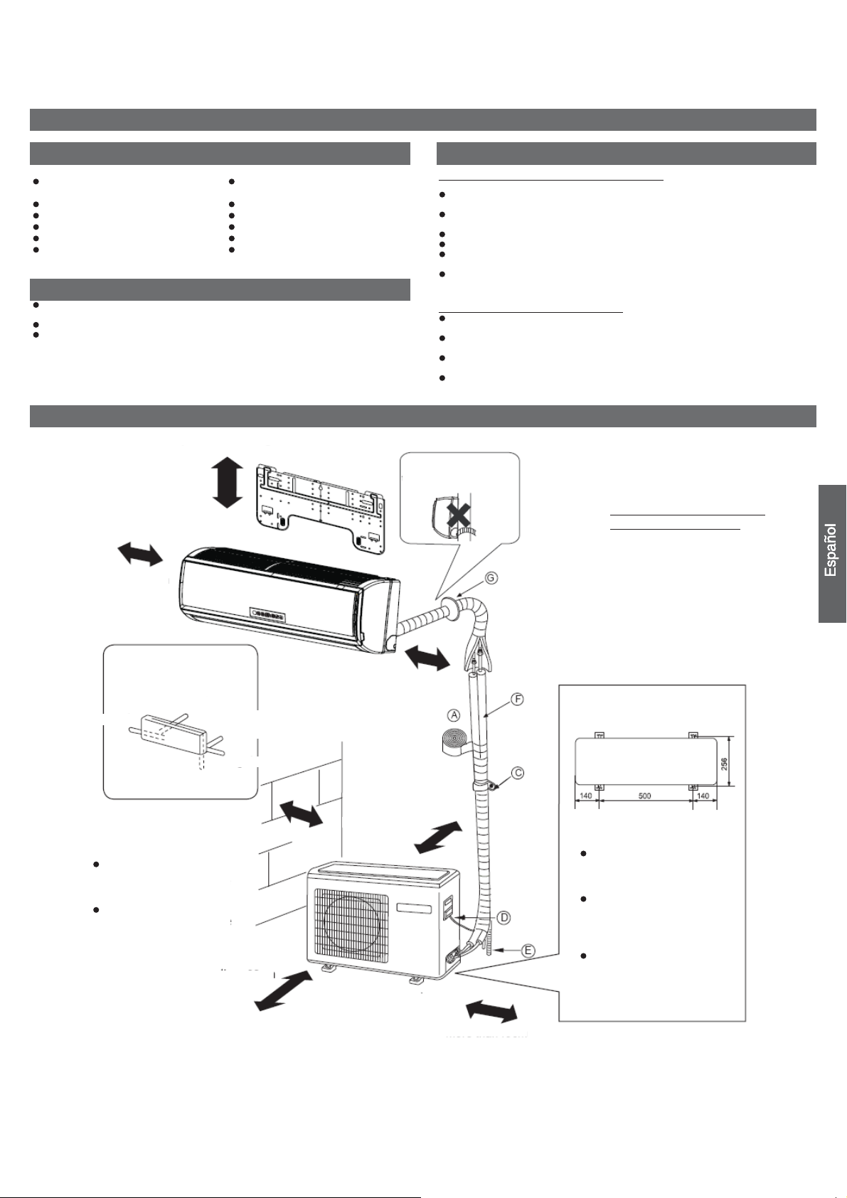
Diagrama para la instalación de aparatos interiores y exteriores
Los modelos cumplen la norma R410A sobre refrigerantes libres de HCFC
más de 5cm
más de 10cm
Selección del lugar de instalación
Unidad interior – Elija una ubicación que seaFirme y que no provoque
vibraciones, que pueda soportar la unidad adecuadamente.
Que no se vea afectada por calor o vapor generado en las cercanías y donde las
tomas de entrada y salida no estén obstruidas.
Que permita un drenaje sencillo y en el que puedan conectarse los tubos a la
unidad exterior.
Donde el aire frío pueda distribuirse uniformemente por la sala.
Que esté cerca de una toma de suministro eléctrico. (Consulte los diagramas).
Coloque la unidad interior de modo que se encuentre a más de 1m de televisiones,
radios, aparatos inalámbricos y lámparas fluorescentes.
En el caso de fijar el control remoto a una pared, colóquelo donde la unidad interior
pueda recibir su señal mientras estén encendidas las lámparas fluorescentes de la
sala.
Unidad exterior – Elija una ubicación
Que no se vea afectada por la lluvia o la luz solar directa y suficientemente
ventilada.
Que permita soportar el peso de la unidad y que no amplifique el ruido y las
vibraciones.
Donde los residuos y el viento generado por la unidad no causen una molestia a los
vecinos.
Coloque la unidad en un lugar en el que pueda disponerse de la distancia de
separación marcada XX en la figura anterior.
Debe prestarse atención
a la pendiente de la
manguera de drenaje
Componentes opcionales para
la instalación de los tubos
A Cinta no adhesiva
○
B Cinta adhesiva
○
C Soporte (L.S) con tornillos
○
D Conexión de cable eléctrico
○
para interior y exterior
E Manguera de drenaje
○
F Material aislante de calor
○
G Cubierta de orificio de
○
entubación
Organización de la dirección
de los tubos
Izquierda trasera
Izquierda
Inferior
Las marcas comprendidas
entre
AyGenla
ilustración corresponden a
los números de las piezas.
La distancia entre la unidad
interior y el suelo debe ser
superior a 2m.
La ilustración anterior debe utilizarse solamente como referencia. Puede que su aparato no coincida exactamente con ella.
Lea este manual antes de la instalación
Explique el uso del aparato al usuario siguiendo las instrucciones de este manual.
Derecha
trasera
Derecha
más de 60cm
más de 10cm
más de 10cm
más de 10cm
más de 15cm
Dimensiones de fijación al suelo
de la unidad exterior (Unidad:mm)
Fijación de la unidad exterior
Fije la unidad a un bloque de
cemento con pernos (10mm) y
tuercas firme y
horizontalmente.
Si instala la unidad sobre una
pared, techo o tejado, instale
un soporte con clavos o cables
considerando la posibilidad de
terremotos o viento fuerte.
Si la vibración afectase a la
casa, fije la unidad instalando
una alfombra de absorción de
vibraciones.
5
Accesorios
A
Control remoto (1)
Batería seca R-03 (2) Acolchado (4)
Placa de montaje(1) Codo de drenaje (1)
Tapón de plástico (4)
Tornillo Ø4X25 (4)
Manguera de
drenaje (1)
Placa de soporte del tubo (1).
Selección de tubo
81 araP 21 araP
Tubo de líquido (Ø) 6,35mm (1/4") 6,35mm (1/4")
Tubo de gas (Ø) 9,52mm (3/8") 12,7mm (1/2")
NOTA: El grosor del tubo debe ser, al menos, de 0,8mm.
Unidad interior
Instalar la placa de montaje y ubicar el orificio en la pared
Al fijar por primera vez la placa de montaje
1. Nivele correctamente la placa a fijar contra la pared basándose en pilares o
dinteles cercanos y fije temporalmente la placa con un clavo de acero.
2. Asegúrese de nuevo de que la placa se encuentre bien nivelada colgando una
plomada desde el punto superior central de la placa. Una vez comprobado, fije la
placa con el clavo de acero de fijación.
3. Busque la ubicación del orificio de pared A utilizando un metro.
1. Pase la manguera aislante a través del hueco de los materiales de aislamiento
de calor de la unidad interior.
2. Inserte los cables eléctricos de interior / exterior a través de la parte trasera de la
unidad interior y tire de ellos desde la parte delantera. A continuación, conéctelos.
3. Cubra la cara de sellado con aceite refrigerante y conecte los tubos.
Cubra la conexión con material aislante de calor y asegúrese de fijarla con cinta
adhesiva.
Material aislante
de calor
Cubierta de
entubación derecha
Cubierta de
entubación inferior
Fijación con cinta
adhesiva
Los cables eléctricos de interior/exterior deben conectarse a la entubación del
refrigerante utilizando cinta protectora.
Cubierta de
entubación
izquierda
Manguera de
drenaje
Cable eléctrico de interior/exterior
Entubación
Placa de
soporte del
tubo
[Entubación en otra dirección]
Corte con una cuchilla la cubierta de entubación de acuerdo con la dirección de
entubación y doble los tubos de acuerdo con la posición del orificio en la pares.
Tenga cuidado de no romper los tubos al doblarlos.
Conecte previamente el cable eléctrico de interior / exterior y tire de la conexión
al aislante de calor del componente de conexión.
Fijación de la unidad interior
Cuelgue con seguridad la unidad de las muescas
superiores de la placa de montaje. Mueva el bastidor
hacia los lados para verificar que la fijación se haya
realizado de la forma correcta.
Para fijar el bastidor a la placa de montaje, sostenga el
aislante del bastidor por debajo y colóquelo en posición
perpendicular.
placa de montaje
Descarga de la unidad interior
Al montar la placa de montaje fijándola a una
barra lateral y un dintel
Fije una barra de montaje (se vende por separado) a la barra lateral y el dintel, y
asegure la placa a la barra de montaje fijada.
Consulte la sección anterior "Al fijar por primera vez la placa de montaje" para más
información acerca del orificio de la pared.
Practicar un orificio en la pared e instalar la cubierta del orificio de entubación
Practique un orificio de 60mm de diámetro con pendiente ligeramente
descendiente hacia el exterior de la pared.
Instale la cubierta del orificio de entubación y séllela con masilla después de la
instalación.
Orificio de pared
Ø60mm
Cara interior
(Sección del orificio de pared)
Grosor de la pared
Cara exterior
Tubo del orificio de entubación
Al descargar la unidad interior, utilice la mano
para levantar el bastidor. Levante entonces la
parte inferior del bastidor llevándolo hacia
fuera ligeramente y levante la unidad hasta
que se separe de la placa de montaje.
Conexión de los cables eléctricos de interior/exterior
gancho
placa de
montaje
Extraer la cubierta del cableado
Extraiga la cubierta de los terminales situada en la esquina inferior
derecha de la unidad interior. Extraiga entonces la cubierta del
cableado desenroscando los tornillos.
Al conectar el cable después de instalar la
unidad de interior
1. Inserte desde fuera el cable en la sala a través del lado izquierdo del
orificio de la pared en el que ya se encuentra el tubo.
2. Tire del cable desde el lado delantero y conecte el cable creando un
bucle.
Al conectar el cable antes de instalar la unidad
de interior
Inserte el cable desde la parte trasera de la unidad y tire desde la parte delantera.
Ajuste el arnés de cableado de la unidad al soporte del conducto por medio de la
tuerca de bloqueo.
Devuelva el soporte del conducto a su estado original utilizando tornillos.
Instalación de la unidad interior
Extracción de los tubos
[ Entubación trasera ]
Extraiga los tubos y la manguera de drenaje y fíjelos con cinta adhesiva
[IzquierdaEntubación trasera izquierda]
En caso de realizar la entubación por el lado izquierdo, corte con una cuchilla la
cubierta de la entubación izquierda.
En caso de realizar la entubación a través de la parte trasera izquierda, doble los
tubos de acuerdo con la dirección de entubación que figura en la marca del orificio
de entubación trasera izquierda, ubicada sobre los materiales aislantes.
6
Tuerca de bloqueo
Soporte del conducto
Nota
rnés de cableado
de la unidad
Corte el fijador de 6 ranuras
Al conectar el cable, confirme el número de terminales de las unidades
interior y exterior detenidamente. Si el cableado no se ha realizado
correctamente no se podrá utilizar el aparato correctamente,
provocándose un defecto.
Unidad interio
r
ALIMENTACIÓN
Cable de alimentación:≥3G1.5mm
Unidad exterior
Asegúrese de que no penetren residuos o suciedad en el tubo.
La longitud estándar del tubo es de 5m. Si el tubo tiene más de 7m, se verán
afectadas las funciones de la unidad. Si es necesario alargar el tubo, deberá cargarse
refrigerante adicional a razón de 20 g/m. No obstante, la carga de refrigerante deberá
ser realizada por un ingeniero profesional en aire acondicionado. Antes de añadir
refrigerante adicional, realice una purga de aire desde los tubos refrigerantes y la
unidad interior utilizando una bomba de vacío y cargue después el refrigerante
adicional.
PRECAUCIÓN
Unidad exterior
Unidad interior
Unidad interior
2
Unidad exterior
Unidad exterior
Filtro de aceite
Unidad interior
Elevación máx. Amáx=10m
En caso de que la elevación A sea
superior a 5m, el filtro de aceite
debe instalarse cada 5 ~ 7m.
Longitud máx.: Bmáx =15m
En caso de que la longitud del tubo
B sea superior a 10m, deberá
cargarse el refrigerante a razón de
20 g/m.
a la unidad interior A
Unidad interior
ALIMENTACIÓN
Cable de alimentación:≥3G2.5mm
2
1. Si el cable de alimentación está dañado deberá ser reemplazado por el fabricante,
agente de servicio o profesional cualificado. El tipo de cable de conexión es
H05RN-F o H07RN-F.
2. Si el fusible de la placa PC está roto, cámbielo por otro de tipo T. 3.15A/250V.
3. El método de cableado debe satisfacer los requisitos de las normas locales de
cableado.
4. Después de la instalación, el enchufe de alimentación debe encontrarse ubicado
en un lugar fácilmente accesible.
5. Debe instalarse un interruptor en el cableado fijo. El interruptor deberá ser de tipo
omnipolar y la distancia entre los dos contactos no deberá ser inferior a 3mm.
Unidad exterior
Instalación de la unidad exterior
Instale la unidad exterior de acuerdo con el diagrama de instalación de unidades
interiores y exteriores.
Conexión de los tubos
Para doblar un tubo, intente hacer la curva lo más suave posible para no aplastar el
tubo. El radio de doblado debe ser de entre 30 y 40mm o superior.
Será más sencillo conectar en primer lugar el tubo de gas.
El tubo de conexión es especial para el tipo R410A.
Media unión
Llave
Tuerca
cónica
Llave
dinamométrica
Si se fuerza la fijación sin aplicar centrado podrían
dañarse los tubos y provocarse una fuga de gas.
Diámetro del tubo (ø) Par de apriete
Lado de líquido 6,35 mm (1/4") 18N.m
Lado de líquido/gas 9,52mm (3/8") 42 N.m
Lado de gas 12,7mm (1/2") 55N.m
Lado de gas 15,88mm (5/8") 60 N.m
Conexión
Extraiga el panel (superior) quitando los 5 tornillos.
Extraiga los tapones de la placa del conducto.
Ajuste temporalmente los tubos del conducto el la placa del conducto.
Conecte la fuente de alimentación y el arnés de cableado de la unidad a los
terminales correspondientes de la placa de terminales.
Conecte la unidad a masa de acuerdo a la normativa vigente.
Deje unos centímetros extra de alambre para realizar conexiones.
Utilice tuercas de bloqueo para asegurar los tubos del conducto.
Tap ó n
Arnés de cableado de la unidad
Tuerca de bloqueo
Placa de conducción
Fuente de alimentación
Conector del conducto
Panel (superior)
Instalación del codo de drenaje
Si utiliza un codo de drenaje, instálelo como indica la
figura. (Nota: sólo para unidades con bomba de calor).
Método de purgado: para utilizar una bomba de vacío
1. Retire el tapón del puerto de mantenimiento de la válvula de 3 vías, el tapón del
vástago de la válvula de 2 vías y 3 vías, y conecte el puerto de mantenimiento a la
manguera de proyección de carga (inferior) del colector. Conecte entonces la
manguera de proyección de carga (central) del colector a la bomba de vacío.
2. Abra la espita inferior del colector y accione la bomba de vacío. Si el indicador de
la escala (inferior) alcanza la condición de vacío por un momento, compruebe de
nuevo el punto 1.
3. Succione durante 15 minutos. Compruebe el nivel medido, que deberá ser de
-0.1MPa (76 cm Hg) en el lado de baja presión. Tras finalizar la succión, cierre la
espita inferior del colector y detenga la bomba de vacío. Compruebe el
funcionamiento de las escala y manténgala durante 1-2 min. Si la escala retrocede
a pesar de ajustarse, realice de nuevo los trabajos de conicidad y vuelva al punto
3.
4. Abra el vástago de la válvula de 2 vías 90 grados hacia la izquierda. Después de 6
segundos, cierre la válvula de 2 vías e inspeccione si existen fugas de gas.
7
5. ¿No existen fugas de gas?
Conti
En caso de que exista una fuga de gas, apriete las conexiones de los
tubos. Si la fuga se detiene, proceda al paso 6.
Si la fuga de gas no se detiene, descargue todo el refrigerante a través
del puerto de mantenimiento. Después de realizar de nuevo la
operación de conicidad y succión, rellene con el refrigerante
6. Desconecte la manguera de carga del puerto de mantenimiento y abra las válvulas
de 2 y 3 vías. Gire el vástago de la válvula hacia la izquierda.
7. Para evitar fugas de gas, gire el tapón del puerto de mantenimiento y el tapón del
vástago de las válvulas de 2 y 3 vías un poco por encima del punto en el que la
torsión aumenta súbitamente.
8. Después de instalar los tapones, compruebe si existen fugas de gas a su
alrededor.
Paso 1.
Tubo (para R410A)
especificado desde el cilindro de gas.
Lateral de líquido de la válvula de 2 vías
Lateral de gas de la válvula de 3 vías
Colector (para R410A)
Junta de retención de contracorriente
Bomba de vacío (para R410A)
Paso 2.
Abrir
Paso 3.
Cerrar
Durante el drenaje
Instale la manguera de drenaje formando una pendiente descendiente.
No practique el drenaje como se muestra a continuación.
Menos de
5cm
Se alza por la
mitad.
Deposite agua en la bandeja de drenaje de la unidad interior y confirme que el
drenaje se realiza correctamente hacia fuera.
En caso de que la manguera de drenaje se encuentre en una sala, asegúrese de
aplicar aislante de calor.
El extremo está
sumergido en
agua.
Está ondulado.
La separación con
el suelo es
demasiado
pequeña
Se aprecia mal olor
de una acequia
■ Etiqueta de carga de refrigerante
ene gasesfluoradosde efecto
invernadero regulados por el Protocolo de
Kioto.
Paso 4.
Abrir 90º
Válvula de 2 vías
Si existen fugas de refrigerante en el aire acondicionado, será necesario
descargar todo el refrigerante. Succione primero, y cargue líquido
refrigerante en el acondicionador de aire de acuerdo con la cantidad
marcada en la placa de valores nominales.
No permita que penetren otros medios de refrigeración (excepto el
especificado, R410A) o aire en el sistema de circulación del refrigerante.
Si ocurriese, se acumularía una presión anormalmente alta en el sistema
que podría provocar roturas y lesiones personales.
Válvula de 2 vías
Válvula de 3 vías
Válvula de 3 vías
Paso 6.
Paso 7.
Tapa del puerto de mantenimiento
PRECAUCIÓN
Válvula de 2 vías
Válvula de 3 vías
Válvula de 2 vías
Válvula de 3 vías
Tapa del vástago de
válvula
Tapa del vástago de
válvula
Instalación de la fuente de alimentación
La fuente de alimentación debe utilizarse exclusivamente con el aparato de aire
acondicionado. (Más de 10A)
En caso de instalar el aire acondicionado en un lugar húmedo, instale un interruptor
de fugas de masa.
Para realizar la instalación en otro lugar, utilice un interruptor de circuito situado lo
más lejos posible.
Trabajos de corte y conicidad de los tubos
El corte del tubo se realiza con un cortador de tubos. Deberán eliminarse las
rebabas.
Después de insertar la tuerca cónica deberá procederse a realizar los trabajos de
conicidad.
Herramienta de conicidad
para R410A
De tipo acoplamiento De tipo acoplamiento (tipo rígido) De tipo palom eta (tipo imperial)
Cuchilla de conicidad
Herramienta de conicidad convencional
1. Cortar el tubo
2. Eliminar las rebabas
mm0,2~5,1 mm5,1~0,1 mm5,0~0 A
Este producto contiene gases fluorados de efecto invernadero regulados por el
Protocolo de Kioto. No los libere libremente a la atmósfera.
Tipo de refrigerante: R410A
Valor GWP*: 1975
GWP = Potencial de contribución al calentamiento global
Escriba con tinta indeleble:
• 1 La carga de refrigerante que contiene el producto de fábrica
• 2 La cantidad de refrigerante adicional cargada durante la instalación y
• 1+2 La carga total de refrigerante
en la etiqueta de carga de refrigerante suministrada con el producto.
Una vez escritos los datos correspondientes, la etiqueta deberá adherirse cerca de la
conexión de carga del producto (por ejemplo, sobre la parte interna de la cubierta de
la válvula de retención).
Contiene gases fluorados de efecto invernadero regulados por el Protocolo
A
de Kioto.
B Carga de refrigerante que contiene el producto de fábrica: consulte la placa
de características de la unidad.
C Cantidad de refrigerante adicional cargada durante la instalación.
D Carga total de refrigerante.
E Unidad exterior.
F Botella de refrigerante y colector de carga.
■ Prueba de instalación y ejecución de la prueba
■ Explique al cliente cómo utilizar el aparato utilizando el manual de instrucciones.
Compruebe los siguientes puntos de prueba
□ ¿Existe una fuga de gas en la conexión del tubo?
□ ¿Aislamiento de calor de la conexión del tubo?
□ ¿Están los cables de conexión interiores y exteriores firmemente insertados en
el bloque de terminales?
□ ¿Están los cables de conexión interior y exterior fijados firmemente?
□ ¿Se ha realizado el drenaje correctamente?
□ ¿Está la línea de tierra conectada con seguridad?
□ ¿Está la unidad interior fijada con seguridad?
□ ¿Cumple la normativa la fuente de voltaje?
□ ¿Se aprecian ruidos?
□ ¿Está la lámpara iluminada normalmente?
□ ¿Se realizan normalmente las operaciones de calentamiento (con la bomba de
calor) y refrigeración?
□ ¿Funciona correctamente el regulador de temperatura de la sala?
Escriba una marca en los recuadros
Correcto
Delgado
3. Insertar la tuerca
cónica
Daño de
conicidad
4. Tubo cónico
Incorrecto
Grieta Parcial
Demasiado
fuera
8
Manuel d'installation d'un climatiseur de pièce
A
A
Il fautfai
Préparation
Outillage requis pour l'installation
Marteau Clé dynamométrique (17 mm, 22 mm,
Pince Coupe-tube
Scie à métaux Outil d'évasement
Perceuse Couteau
Clé à ergot (17,19 et 26 mm) Rubans à mesurer
Détecteur de fuite de gaz ou solution à
base d'eau savonneuse
26 mm)
Alésoir
Source d'alimentation
Avant de brancher la fiche dans la prise, vérifiez que la tension est sans faille. La
source d'alimentation correspond aux informations sur la plaque signalétique.
Installez un circuit d'alimentation auxiliaire exclusive.
Une prise doit être installée de manière à ce que le câble d'alimentation puisse être
branché facilement. Ne pas prolonger le câble en le coupant.
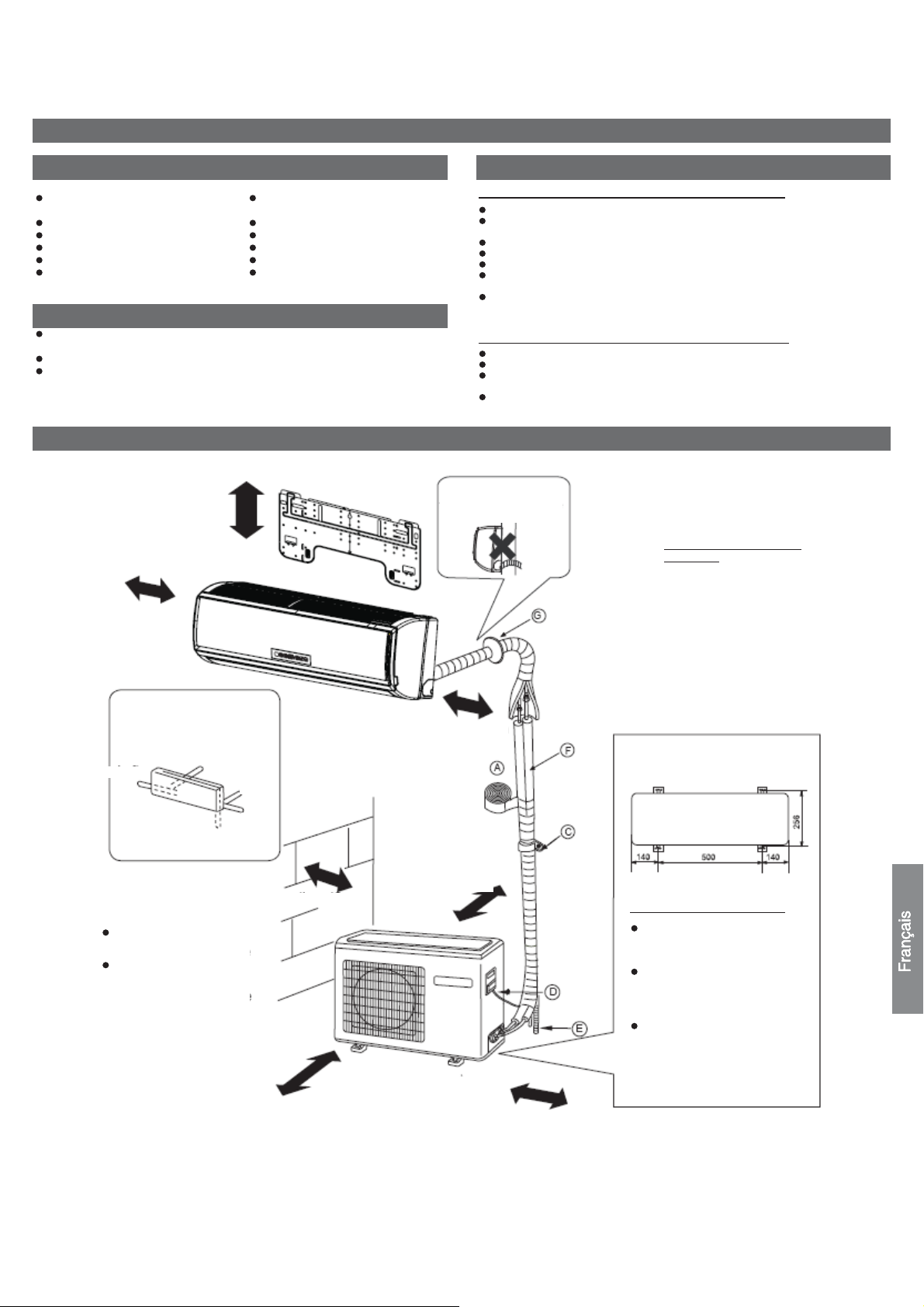
Schéma de l'installation des unités intérieures et extérieures
Les modèles utilisent le réfrigérant R410A sans HCFC
plus de 5cm
plus de 10cm
Sélection de l'emplacement pour l'installation
Unité intérieure – Sélectionnez un emplacement qui soit
Solide sans vibration et offrant un support suffisant.
N'est pas affecté par de la chaleur ou de la vapeur générées dans les environs et
doit garantir que l'entrée et la sortie de l'unité ne seront pas gênées.
Facilement vidangeable avec la tuyauterie connectée à l'unité extérieure.
Où l'air froid puisse être réparti dans toute la pièce.
Près d'une prise de courant (Voir les schémas).
Sélectionnez un emplacement à une distance d'au moins (1) m par rapport aux
postes de télévision, radio, appareils sans fil et lampes fluorescentes.
En cas de fixation de la télécommande sur un mur, sélectionnez l'emplacement de
sorte que l'unité intérieure puisse recevoir les signaux lorsque les lampes
fluorescentes sont allumées dans la pièce.
Unité extérieure – Sélectionnez un emplacement qui soit
non exposé à la pluie ou à la lumière du jour et qui soit suffisamment ventilé.
Capable de supporter l'unité où les vibrations et le bruit n'augmentent pas.
Sélectionnez un emplacement où le vent et le bruit ne risquent pas de gêner les
voisins.
Sélectionnez l'emplacement où la distance XX telle que marquée sur l'illustration
ci-dessus est disponible.
re
particulièrement attention
au soulèvement du tuyau
de vidange.
Pièces en option pour la
tuyauterie
A Ruban non adhésif
○
B Ruban adhésif
○
C Selle (L.S) avec vis
○
D Raccordement du câble
○
électrique entre unités
intérieures et extérieures
E Tuyau de vidange
○
F Matériau d'isolation thermique
○
G Cache trou de tuyauterie
○
Disposition des directions
de la tuyauterie
rrièregauche
Gauche
En bas
Les marques deAàG
sur la figure représentent
les références de pièce.
La distance entre l'unité
intérieure et le sol est de
2 m minimum.
L'illustration ci-dessus est indiquée à titre de référence uniquement. Il est possible que votre produit soit différent.
Lisez ce manuel avant de procéder à l'installation.
Communiquez à l'utilisateur suffisamment d'informations sur l'exploitation de l'unité selon ce manuel.
rrière
droite
Droite
plus de 60cm
plus de 10cm
plus de 10cm
plus de 10cm
plus de 15cm
Dimensions de fixation au sol de
l'unité extérieure (Unité:mm)
Fixation de l'unité extérieure
Fixez l'unité horizontalement et
solidement sur le béton ou un
bloc de béton avec des boulons
(10 mm) et des écrous
Lorsque l'unité doit être installée
sur un mur, un toit ou la toiture,
fixez un support avec des clous
ou des fils en tenant compte des
séismes et vents forts.
Si des vibrations risquent
d'affecter la maison, fixez l'unité
avec un tapis anti-vibration
9

Accessoires
Télécommande (1) Tuyau de vidange (1)
Batterie sèche R-03 (2) Coussinet (4)
Plaque de fixation (1) Coude de vidange (1)
Capuchon en plastique (4)
Vis Ø4X25 (4)
Plaque de support de tuyau (1)
Sélection du tuyau
Pour 12 Pour 18
Tuyau de liquide (Ø) 6,35mm (1/4”) 6,35mm (1/4”)
Tuyau de gaz (Ø) 9,52mm (3/8”) 12,7mm (1/2”)
REMARQUE : L’épaisseur de la paroi des tuyaux doit être d’au moins 0,8 mm.
Unité intérieure
Installation de la plaque de fixation et positionnement du trou dans le mur
Lorsque la plaque de fixation est installée pour
la 1e fois
1. Localisez en fonction des piliers ou des linteaux autour, un endroit de fixation
contre le mur, puis attachez la plaque temporairement avec un clou en acier.
2. Assurez-vous à nouveau que le niveau de la plaque est approprié en suspendant
un fil avec un poids du dessus central de la plaque, puis fixez solidement la plaque
avec le clou en acier.
3. Localisez le trou A dans le mur avec un ruban à mesurer
1. Insérez le flexible d'évacuation dans l'encoche des matériaux d'isolation thermique
de l'unité intérieure.
2. Introduisez le câble électrique de l'unité intérieure/extérieure de l'endos de l'unité
intérieure et sortez-le par l'avant puis effectuez la connexion.
3. Enduisez le joint évasé avec de l'huile réfrigérante et connectez les tuyaux.
Recouvrez la pièce de connexion avec des matériaux d'isolation thermique et fixez
avec du ruban adhésif.
Câble électrique des unités
intérieures/extérieures
Matériau d'isolation
thermique
Couvercle pour
tuyauterie de droite
Couvercle de dessous
Fixez avec du ruban
adhésif
Le câble des unités intérieures/extérieures et le tuyau de vidange doivent être fixé
au tuyau de réfrigérant avec un ruban protecteur.
Couvercle pour
tuyauterie de
gauche
Tuyau de
vidange
Tuyauterie
Plaque de support de
tuyau
[Tuyauterie dans une autre direction].
A l'aide d'une pince, découpez le couvercle pour la tuyauterie en fonction de la
direction de la tuyauterie et cintrez ensuite le tuyau selon la position du trou dans le
mur. Lors du cintrage, prenez soin de ne pas écraser les tuyaux.
Connectez au préalable le câble des unités intérieures/extérieures et recouvrez
ensuite les câbles connectés avec l'isolation.
Fixation de l'unité intérieure
Suspendez l'unité sur les encoches supérieures de la
plaque de fixation. Déplacez l'unité d'un côté vers l'autre
pour vérifier la fixation.
Pour fixer le corps sur la plaque de fixation, soutenez le
corps du dessous et reposez-le perpendiculairement.
Plaque de fixation
Déballage de l'unité intérieure
Lorsque vous déballez l'unité intérieure,
utilisez vos mains pour soulever le corps
puis sortez la partie inférieure du corps
légèrement vers l'extérieur et soulevez
ensuite l’unité jusqu'au dégagement de la
plaque de fixation.
Crochet
Plaque de
fixation
Lorsque la plaque de fixation est installée sur
une barre latérale ou un linteau
Installer une barre de fixation (vendue séparément) à la barre latérale et au linteau
puis resserrez la plaque à la barre de fixation fixe.
Voir la position du trou dans le mur dans la section précédente intitulée Lorsque la
plaque de fixation est installée pour la 1
e
fois.
Faire un trou dans le mur et installer le cache-trou de tuyauterie
Percez un orifice de 60mm de diamètre, descendant légèrement en direction de la
face extérieure du mur.
Installez le cache trou de tuyauterie et scellez avec du mastic après l'installation
Trou dans le mur
Côté intérieur
(Sezione del foro su parete)
Epaisseur de la paroi
Tubo del foro tubatura
Côté intérieur
Installation de l'unité intérieure
Schéma de la tuyauterie
[Tuyauterie arrière]
Acheminez les tuyaux et le tuyau de vidange que vous fixez ensuite avec du ruban
adhésif.
[Gauche - Tuyauterie arrière gauche]
Dans le cas d'une tuyauterie à gauche, découpez, avec une pince, le couvercle
pour la tuyauterie gauche.
Pour une tuyauterie à l'arrière gauche, cintrez les tuyaux selon le sens de la
tuyauterie jusqu'à la marque du trou pour une tuyauterie arrière-gauche qui est
marquée sur les matériaux d'isolation thermique.
Connexion du câble des unités intérieures/extérieures
zsDépose du cache-câble
Enlevez le cache-borne en bas à droite de l'unité intérieure et
séparez le couvercle du câblage en desserrant les vis.
Connexion du câble après l'installation de
l'unité intérieure
1. Insérez le câble de l'extérieur de la pièce dans le côté gauche
du trou dans le mur dans lequel se trouve le tuyau.
2. Tirez le câble sur le côté avant et connectez-le en formant
une boucle.
Connexion du câble avant l'installation de
l'unité intérieure
Insérez le cordon depuis l'arrière de l'unité et sortez par l'avant.
Fixez le faisceau de câbles de l'unité au support du conduit avec un écrou de
blocage.
Placez le support du conduit à sa position initiale à l'aide d'une vis.
Ecrou de blocage
Support de conduit
Remarque
Lors de la connexion du câble, confirmez le numéro de la borne des
unités intérieures et extérieures. Si le câblage est incorrect, le
fonctionnement sera incorrect et entraînera des dommages.
Faisceau de
câbles de
Effectuez les 6
10
Unité intérieure
A
A
2
A
A
Unité extérieure
Assurez-vous qu'aucune impureté ni débris ne sont entrés dans le tuyau.
La longueur standard du tuyau est de 5 m. Au delà de 7 m, l'unité ne fonctionnera pas
correctement. S'il faut rallonger le tuyau, le réfrigérant doit être chargé selon 20 g/m.
Toutefois, la charge de réfrigérant doit être exécuté par un professionnel de la
climatisation. Avant d'ajouter du réfrigérant, purgez l'air des tuyaux de réfrigération et
de l'unité intérieure avec pompe à vide. Chargez ensuite le réfrigérant
supplémentaire.
VERTISSEMENT
Unité extérieure
Unité intérieure
LIMENTATION
Câble électrique 3G1.5mm
2
Unité extérieure A
Unité intérieure
LIMENTATION
Câble électrique 3G2.5mm
1. Si le cordon d'alimentation est endommagé, il doit être remplacé par le fabricant, un
de ses agents d'entretien ou une personne qualifiée. Le type du fil de connexion
est H05RN-F ou H07RN-F.
2. Si le fusible sur la carte PC a fondu, remplacez-le avec le type T. 3.15A/ 250V.
3. La méthode de câblage doit être conforme aux normes locales de câblage.
4. Après installation, la prise de courant doit être d'accès facile.
5. Un disjoncteur doit être incorporé au câblage fixe. Le disjoncteur doit être
omnipolaire et la distance entre ses deux contacts ne doit pas être inférieure à 3
mm.
Unité extérieure
Installation de l’unité extérieure
Effectuez l'installation selon le schéma d'installation des unités intérieures et
extérieures
Raccords de tuyauterie
Lorsque vous cintrez un tuyau, prenez soin de ne pas écraser le tuyau. Le rayon
de cintrage doit être entre 30 et 40 mm ou plus long.
Connectez d'abord le côté gaz pour faciliter la suite des travaux.
Le tuyau de raccordement est réservé à R410A.
Demi-raccord Clé
Ecrou
d'évasement
Clé
dynamométrique
Le serrage forcé sans prêter attention au centrage
peut endommager les filets et entraîner des fuites de
gaz.
Diamètre du tuyau (Ø)
Côté liquide 6,35 mm (1/4 po) 18N.m
Côté liquide/gaz 9,52 mm (3/8 po) 42 N.m
Gaz 12,7mm (1/2") 55N.m
Gaz 15,88mm (5/8") 60 N.m
Couple de
serrage
Unité intérieure
Unité extérieure
Hauteur max: Amax=10m
Unité extérieure
Piège dl'huile
Unité intérieure
Si la hauteur A dépasse les
5m, installez un piège à huile
tous les 5 à 7 m
Longueur max: Bmax=15m
Si la longueur du tuyau B
dépasse les 10m, le
réfrigérant doit être chargé à
20 g/m.
Raccordement
Enlevez le panneau (supérieur) en desserrant les 5 vis.
Retirez les bouchons de la plaque du conduit.
Installez temporairement des tubes de conduit sur la plaque de conduit.
Connectez la source d'alimentation et le faisceau des câbles de l'unité aux bornes
correspondantes sur le bornier.
Mettez l'unité à la masse conformément aux codes locaux.
Ajoutez plusieurs cm de câble pour effectuer les connexions.
Utilisez des contre-écrous pour fixer les tubes de conduit.
Ecrou de blocage
Panneau (supérieur)
Plaque de conduit
Bouchon
Faisceau de câbles de l'unité
limentation
Connecteur de conduit
Fixation d'un drain coudé
Si vous utilisez un drain coudé, procédez à la fixation selon
l'illustration. (Remarque : (uniquement pour la pompe
thermique)
Méthode de purge: Pour utiliser une pompe à vide:
1. Enlevez le capuchon de l'orifice d'entretien de la vanne à 3 voies, le capuchon
du robinet de la vanne à 2 voies et à 3 voies. Connectez ensuite l'orifice
d'entretien dans la projection du tuyau de charge (bas) pour le collecteur à
manomètre. Connectez ensuite la projection du tuyau de charge (centre) pour
le collecteur à manomètre dans la pompe à vide.
2. Ouvrez la poignée du collecteur à manomètre au niveau bas. Mettez la pompe
à vide en marche. Si l’indicateur se déplace (bas), précipitez l'état de vide et
vérifiez 1 à nouveau.
3. Mettez sous vide pendant plus de 15 min Vérifiez également le manomètre qui
doit indiquer -0.1MPa (76 cm Hg) sur le côté basse pression. Après avoir
effectué le vide, fermez la poignée Lo dans le collecteur à manomètre et
arrêtez l'opération de la pompe à vide. Inspectez l’indicateur et observez
pendant 1 à 2 minutes. Si l’indicateur revient en dépit du serrage, reprenez
l'opération d'évasement en revenant au début de l'étape 3.
4. Ouvrez le robinet de la vanne à 2 voies dans le sens antihoraire jusqu'à
90 degrés. Environ 6 secondes plus tard, fermez la vanne à 2 voies et
inspectez afin de détecter toute fuite de gaz.
11
5. Pas de fuite de gaz?
)
)
r
r
En cas de fuite de gaz, resserrez les pièces de connexion du tuyau. Lorsque la
Si elle n'a pas été maîtrisée, videz le réfrigérant de l'orifice d'entretien. Après avoir
effectué l'évasement et le vide, remplissez de réfrigérant indiqué de la bouteille.
6. Détachez le tuyau de charge de l'orifice d'entretien, ouvrez la vanne à 2 et 3
voies. Tournez le robinet de la vanne dans le sens antihoraire.
7. Pour empêcher toute fuite de gaz, tournez le capuchon de l'orifice d'entretien, le
capuchon du robinet des vannes à 2 et 3 voies un peu au-delà du point où le
couple augmente brusquement.
8. Après avoir fixé les capuchons, inspectez-en le tour pour détecter toute trace
de fuite.
Etape 1.
Tube (pour le
modèle R410A
Etape 4.
Ouvrir 90
Vanne à 2 voies
Vanne à 2 voies, côté liquide.
fuite est maîtrisée, passez à l'étape 6
Vanne à 3 voies, côté gaz
Collecteur à manomètre (pour le
modèle R410A)
Joint anti-contre-courant
Pompe à vide (pour le
modèle R410A
Vanne à 2 voies
Vanne à 3 vo ie s
Vanne à 3 voie s
Etape 2.
Ouvri
Etape 3.
Ferme
Etape 6.
Etape 7.
Capuchon de l'orifice d’entretien
Vanne à 2 voies
Vanne à 3 voies
Vanne à 2 voies
Vanne à 3 voies
Capuchon du robinet de
Capuchon du robinet de
AVERTISSEMENT
Si le réfrigérant du climatiseur fuit, il faut vidanger tout le réfrigérant. Mettez
d'abord sous vide, puis chargez le réfrigérant liquide dans le climatiseur d'air
jusqu'à la quantité indiquée sur la plaque signalétique.
Ne laissez pas les autres moyens de réfrigération, sauf pour celui spécifié
(R410A) ou l'air entrer dans le système de circulation du produit de
refroidissement. Toute entrée entraînerait une pression élevée dans le système
au point de le faire craquer et blesser les individus.
Installation du bloc d'alimentation
La source d'alimentation doit être utilisée exclusivement par le climatiseur. (Plus de
10A)
Si le climatiseur doit être installé dans un endroit humide, ajoutez un disjoncteur de
fuite à la masse.
Pour toute installation dans d'autres emplacements, placez le disjoncteur le plus
loin possible.
Travail de coupe et d'évasement de la tuyauterie
La coupe du tuyau doit être effectuée avec un coupe-tuyau. Vous devez nettoyer
les ébavures.
Après avoir inséré l'écrou évasé, vous pouvez procéder au travail d'évasement.
Outil d'évassement
pour R410A
Type à embrayage Type à embrayage (rigide) Type à écrou à oreilles (Imperial)
Matrice de l'outillage
d'évasement
1.Coupez le tuyau
Outil d'évasement classique
mm0,2~5,1 mm5,1~0,1 mm5,0~0 A
2. Nettoyez les ébavures
Vidange
Installez le tuyau de vidange de manière à ce que la pente soit descendante.
Ne pas effectuer la vidange telle qu'illustrée ci-dessous.
Moins de 5cm
Il est surélevé à
mi-chemin.
L'extrémité est
immergée dans
l'eau.
Il ondule :
L'intervalle au sol est
trop petit.
Il y a une odeur
nauséabonde de la
fosse
Versez de l'eau dans le bac de vidange de l'unité intérieure et vérifiez qu'il soit
dirigé vers l'extérieur.
Si le tuyau de vidange est dans une pièce, utilisez une isolation thermique.
■ Etiquette de charge de réfrigérant
Contient des gaz à effet de serre fluorés
couverts par le protocole de Kyoto.
Cet appareil contient des gaz à effet de serre fluorés couverts par le protocole de
Kyoto. Ne pas ventiler à l'air.
Type de réfrigérant : R410A
Valeur de GWP: 1975
GWP = global warming potential - potentiel de réchauffement de la planète.
Merci de remplir à l'encre indélébile;
• 1 la charge de réfrigérant standard de l'appareil
• 2 la quantité supplémentaire de réfrigérant chargée sur place et
• 1+2 la charge totale de réfrigérant.
sur l'étiquette de charge de réfrigérant fournie avec l'appareil.
L'étiquette renseignée doit être collée à proximité du port de chargement de l'appareil
(par ex.sur l'intérieur du couvercle de valeur d'arrêt).
A Contient des gaz à effet de serre fluorés couverts par le protocole de Kyoto.
B Charge de réfrigérant standard de l'unité : voir sur la plaque signalétique de
l'unité
C Quantité supplémentaire de réfrigérant chargée sur place
D Charge totale de réfrigérant
E Unité extérieure
F Cylindre réfrigérant et collecteur de chargement
■ Vérification de l'installation et test de fonctionnement
■ Expliquez le fonctionnement à vos clients en vous servant du manuel.
Vérification des composants pour le test de fonctionnement
Cochez les cases
□ Fuite de gaz dans le raccordement du tuyau?
□ Isolation thermique du tuyau?
□ Les câbles de raccordement des unités intérieures et extérieures sont bien
introduits dans le bornier?
□ Le câble de raccordement des unités intérieures et extérieures est bien fixé?
□ La vidange a été effectuée correctement?
□ Le conduit de masse est correctement connecté?
□ L'unité intérieure est bien fixée?
□ La tension de la source d'alimentation est conforme au code?
□ Y-a-t-il du bruit?
□ La lampe s'allume normalement?
□ Les opérations de refroidissement et de chauffage (avec une pompe thermique)
sont effectuées normalement?
□ Le régulateur de température de la pièce fonctionne normalement?
Correct
Insuffisant
3.Insérez l'écrou
d'évasement
Evasement endommagé
Incorrect
Fissure
4. Tuyau d'évasement
Partiel
Vers exté rieu r
12

Installation Manual of Room Air Conditioner
Preparation
Necessary Tools for Installation
Torque wrench
Hammerƽ
Nipperƽ
Hacksawƽ Pipe cutterƽ
Hole core drillƽ Flaring toolƽ
Spanner(17,19 and 26mm)ƽ Knifeƽ
Gas leakage detector orƽ
soap-and-water solution
ƽ
(17mm,2 2mm, 26mm)
Measuring tapeƽ
Reamerƽ
Power Source
ƽ
Before inserting power plug into receptacle, check the voltage without fail.
The power
Install an exclusive branch circuit of the power.
ƽ
A receptacle shall be set up in a distance where the power cable can be
ƽ
reached.
sourceisthesameasthe
Donotextendthecablebycuttingit.
corresponding name plate.
Drawing for the installation of indoor and outdoor units
ThemodelsadoptHCFCfreeref
more than 10cm
(3 7/8)
more than
10cm (3 7/8)
rigerant R410A
Selection of Installation Place
Indoor Unit - Select a location that is
Robust not causing vibration, where the body can be supported sufficiently.
ƽ
Not affected by heat or steam generated in the vicinity, where inlet and outlet of the
ƽ
unit are not disturbed.
Possible to drain easily, where piping can be connected with the outdoor unit.
ƽ
Where cold air can be spread in a room evenly.
ƽ
Nearby a power receptacle. (Refer to drawings).
ƽ
Place where the distance of more than lm from televisions, radios, wireless apparatuses
ƽ
and fluorescent lamps can be left.
In the case of fixing the remote controller on a wall, place where the indoor unit can
ƽ
receive signals when the fluorescent
Outdoor Unit - Select a location that is
Less affected by rain or direct sunlight and is sufficiently ventilated.
ƽ
Strong enough to bear the unit, where vibration and noise are not increased.
ƽ
Not causing a nuisance to neighbors due to discharged air or noise.
ƽ
A distance marked
ƽ
Attention must be paid to
the pitch of drain hose
G
is available as illustrated in the below figure.
Q
lamps in the room are in use.
Optional parts for piping
Non-adhesive tape
A
Adhesive tape
B
Saddle (L.S) with screws
C
Connecting electric cable
D
forindoorandoutdoor
E
Drain hose
F
Heating insulating material
Piping hole cover
G
Arrangement of piping
directions
more than 10cm
(3 7/8)
A
Left
Rear left
Rear
right
Right
Below
more than 15cm
(5 7/8)
more than 20cm
(7 7/8)
The marks from to
ƽ
G
in the figure are the
A
parts numbers.
Thedistancebetween
ƽ
theindoorunitandthe
floor should be more
than 2m.
more than 60cm
(23 5/8)
more than 25cm
The above picture is for your reference only. Your product may look different.
Read this manual before installation.
Explain the operation of the unit to the user according to this manual.
NO.0010536242
F
C
D
(9 7/8)
Floor fixing dimensions of the
outdoor unit
140 500
(5 1/2)
113.5
(4 1/2)
(Unit:mm / inch)
For:09k 12k 18k
(19 2/3)
For:24k
633
(24 7/8)
140
(5 1/2)
113.5
(4 1/2)
256
(10 1/16)
340
(13 1/2)
Fixing of outdoor unit
Fix the unit to concrete or blockƽ
with bolts (10mm) and nuts firmly
E
and horizontally.
When fitting the unit to wall
ƽ
surface, roof or rooftop, fix
a supporter securely with nails
orwiresinconsideration of
earthquake and strong wind.
If vibration may affect the
ƽ
house, fix the unit by attaching a
vibration-proof mat.

Accessory parts
Remote controller (1)
AAA dry battery (2)
Mounting plate (1)
Plastic cap (4)
Ø4X25 Screw
(4)
Drain hose (1)
Cushion (4)
Drain-elbow (1)
Pipe supporting plate (1)
Selectionofpipe
Type
Liquid pipe (Ø)
Gaspipe(Ø)
NOTE˖The thickness of the pipe must be 0.8mm(1/16”) at least.
For 09K 12K
6.35mm(1/4”)
9.52mm(3/8”)
For 18K
6.35mm(1/4”)
12.7mm
(1/2”)
For 24K
9.52mm(3/8”)
15.88mm
Indoor unit
FittingoftheMountingPlateand
Whenthemountingplateisfirstfixed
1. Carry out, based on the wall studs or lintels, a
to be fixed against the wall, then temporarily fasten the plate with one steel nail.
2. Make sure once more the proper level of the plate, by
weight from the central top of the plate, then fasten the plate.
3. Find the wall hole location A using a measuring tape
PositioningofthewallHole
proper leveling for the plate
hanging a thread with a
Ø
70mm
B=
(2 3/4)
(5/8”)
[Left·Left-rear piping ]
ƽ
In case of left side piping, cut away, with a nipper, the lid for left piping.
In case of left-rear piping, bend the pipes according to the piping direction to
ƽ
the mark of hole for left-rear piping which is marked on heat insulation materials.
1. Insert the drain hose into the carity of heat insulation materials of indoor unit.
2. Insert the indoor/outdoor electric cable from backside of indoor
ut on the front side, then connect them.
o
3.Coattheflaringsealfacewithrefrigerantoilandconnect pipes.
Cover the connection part with heat insulation materials, cover with adhesive tape.
Heat insulation
Lid for right
piping
Lid for under piping pipe
Fix with adhesive tape
ƽ
Indoor/outdoor electric cable and drain hose must be bound with refrigerant
piping with protecting tape.
Lid for left piping
material
Drain hose
unit, and pull it
Indoor/outdoor electric cable
Piping
Pipe supporting
plate
[ Other piping direction ]
ƽ
Cut away, with a nipper, the lid for piping according to the piping direction and
then bend the pipe according to the position of wall hole. When bending, be
careful not to crush
ƽ
Connect beforehand the indoor/outdoor electric cable,
connected to the heat insulation of connecting part specially.
pipes.
andthenpulloutthe
Fixing the indoor unit body
Hang the unit body securely onto the upper notches of the
ƽ
mounting plate. Move the body from side to side to verify
its secure fixing.
Inordertofixthebodyontothemountingplate,holdup
ƽ
the body at a slant from the underside and then put it down
perpendicularly.
mounting plate
Unloading of indoor unit body
A=145mm
(5 5/7)
B=
A=145mm
(5 5/7)
Making a Hole on the Wall and Fitting the Piping Hole Cover
Make a hole of 70 mm (2 3/4) in diameter, slightly descending to outside the wall.
ƽ
Install piping hole cover and seal it off with putty after installation
ƽ
Wall hole
Ø
70mm
(2 3/4)
(1 3/8)
35mm
30mm
B= 70mm
A=150mm
(5 7/8)
(1 1/6)
(2 3/4)
Pitch downward for drainage
Ø70mm
(2 3/4)
Indoor side
Thickness of wall
Outdoor side
35mm
(1 3/8)
When you unload the indoor unit, please use
ƽ
your hand to raise the body, then lift the
bottom of the body outward slightly
and lift the unit until it leaves the
mounting plate.
mounting plate
Connecting the indoor/outdoor Electric Cable
Removing the wiring cover
Remove terminal cover at right bottom corner of indoor unit, then takeƽ
off wiring cover by removing its screws.
When connecting the cable after installing the indoor unit
1. Insert from outside the room cable into left side of the wall
hole,inwhichthepipehasalreadyexisted.
2. Pull out the cable on the front side, and connect the cable
making a loop.
When connecting the cable before installing the indoor unit
Insert the cord from the back side of the unit, then pull it out on the front side.
ƽ
Fasten the unit wire harness to the conduit holder using the lock nut.
ƽ
Position the conduit holder to its original state using screw.
ƽ
Installation of the Indoor Unit
[Rearpiping ]
Drawpipesandthedrainhose,thenfastenthemwiththeadhesivetape
ƽ
2
Drawingofpipe
Conduit holder
When connecting the cable, confirm the terminal number of indoor and
Note
outdoor units carefully. If wiring is not correct, improper operation may
occur and cause damage to the units.
Cut the 6 slit sear

Indoor unit
4wire 14AWG
Control Wiring
HSU09VHJ(DB)-W
HSU12VHJ(DB)-W
HSU18VHJ(DB)-W
HSU24VHJ(DB)-W
Power cable:
Power cable:
Power cable:
Power cable:
2wire with ground 12AWG
2wire with ground 12AWG
2wire with ground 12AWG
2wire with ground 12AWG
All models: Control cable: 4wire, 14AWG
Indoor unit
Power
Wiring
Outdoor unit
Outdoor unit
1
(
N
)
2
(L
)
3
(
C
)
1
(
N
)
2
(
L
)
3
(
C
)
Ensure that no dirt or debris enters the pipe.
The standard pipe length is 7m (27 9/16) . If it is over 7m (27 9/16) , the function
of the unit will be
be charged,
be conducted by professional air conditioner servicer. Before adding addi tional
refrigerant, per form air
acuum
a v
affected. If the pipe has to be lengthened, the refrigerant should
accordin
pump,then
g to 20 g/m (0.018 oz/inch)
purging from the refrigerant pipes and indoor unit using
charge additional refr igerant.
. But the charge of refrigerant must
CAUTION
Outdoor unit
Indoor unit
Outdoor unit
Outdoor unit
B
A
Max.Elevation: Amax=1 m
●
In case the elevation A is more●
than 5m, oil trap shoud be
Oil trap
B
A
Indoor unit
installed every 5~7m
●
Max. Length: Bmax=15m
In case the pipe length B is●
more than 10m, the refrigerant
should be charged, according
to 20 g/m.
B
Indoor unit
A
Connection
Take off the panel(top), by removing the 5 screws.
Remove the plugs on the conduit plate.
Temporarily mount the conduit tubes on the conduit plate.
Connect both the power supply and unit wire harness to
the corresponding terminals on the terminal board.
Ground the unit in accordance with local codes.
Allow several extra inches of wire for making wiring
connections.
Use lock nuts to secure conduit tubes.
HSU09XCK-W
HSU12XCK-W
1. If the fuse on PC board is broken please change it with the
T. 3.15A/250V(indoor unit),25A/250V(outdoor unit).
2. The wiring method should be in line with the local wiring standard.
3. After installation, the power plug should be easily reached.
4. A breaker should be incorporated into fixed wiring. The breaker should be
all-pole
switch.
Power cable:
Power cable:
2wire with ground 12AWG
2wire with ground 12AWG
type of
Outdoor unit
Installation of Outdoor Unit
Install according to Drawing for the installation of indoor and
Connection of pipes
To bend a pipe, be careful not to crush the pipe,
and the bending radius should be 30 (1 1/6) to 40
Connecting the pipe of gas side first makes working easier.
The connection pipe is specialized for R410A.
Half union
Spanner
Flare nut
Torque wrench
Forced fastening without careful centering may
damage the threads and cause a leakage of gas.
Pipe Diameter(ǿ) Fastening torque
Liquid side6.35mm(1/4") 18N.m/13.3Ft.lbs
Liquid/Gas side9.52mm(3/8 ") 42 N.m/30.1Ft.lbs
Gas side 12.7mm(1/2") 5 5N.m/40.6Ft.lbs
Gas side 15.88mm(5/8") 60 N.m/44.3Ft.lbs
mm (1 4/7) or longer.
outdoor units
Attaching Drain-Elbow
If the drain-elbow is used,
please attach it as fi gure. (Note:
Only for heat pump unit.)
Purging Method:To use vacuum pump
Remove the service port cap of the 3-way valve and the valve stem cap for both
1.
valves. Connect the low pressure hose from the manifold set to the 3-way valve.
Connect the center hose to the vacuum pump.
Open the handle on low side of manifold and
2.
side gauge reaches a vacuum immediately, ensure the hoses are connected
properly and the low side manifold handle is open.
Vacuum for a minimum of 15 minutes and check the gauge for a proper vacuum.
3.
Open the valve rod stem the 2-way valve counterclockwise to 90 degrees.4.
completion of vacuuming, close the
After the
stop the operation of the vacuum pump.
the vacuum level again in 1-2 minutes. If you lose the vacuum, ensure all
connections are tight and flare the tubes again if needed.
After 6 seconds, close the
2-way valve and inspect for
operate vacuum pump. If the low
handle ‘Lo’ in gaugemanifold and
Leave the hoses connected and check
gas leakage.
3
 Loading...