


Haier HSU-09LEK13-R2-DB, HSU-18HKAG-R2DB, HSU-18LEK13-R2-DB, HSU-09LEK03-R2-DB, HSU-12LEK13-R2-DB User Manual
...SPLIT TYPE ROOM AIR CONDITIONER
OPERATION MANUAL
Contents
PARTS AND FUNCTIONS
OPERATION
MAINTENANCE
CAUTIONS
TROUBLE SHOOTING
HSU-09LEK03/R2(DB)
HSU-12LEK03/R2(DB)
HSU-09LEK13/R2(DB)
HSU-12LEK13/R2(DB)
HSU-18LEK13/R2(DB)
HSU-24LEK13/R2(DB)
HSU-12CKAS(R2DB)
HSU-18CKAS(R2DB)
HSU-12HKAG(R2DB)
HSU-18HKAG(R2DB)
1
2
5
6
7
ƔPlease read this operation manual before using the air conditioner.
Keep this operation manual for future reference.
0010562830

Parts and Functions
 Indoor Unit
|
Inlet |
|
Air Purifying Filter |
||
|
|
|
|
(inside) |
|
Inlet grille |
|
|
|
|
|
Outlet |
|
|
|
|
|
|
Vertical blade |
|
Emergency |
||
|
(adjust left and |
|
|||
Horizontal flap |
|
Switch |
|
||
right air flow) |
|
|
|||
(adjust up and down air flow |
Display board |
|
|||
Don't adjust it manually) |
|
|
|||
|
|
|
|
|
|
Display board |
1 |
2 |
3 |
4 |
5 |
1Signal receiver hole
2ON/OFF display
3Ambient temp.display
When receiving the remote control signal, display the set temperature and in the rest time the room temperature is displayed.
4TIMER ON\OFF display TIMER ON-OFF display SLEEP display
Note to the power failure resume: press the sleep button ten times in five seconds
and enter function after hearing four sounds.And press the sleep button ten times within five
seconds and leave this function after hearing two sounds.
5 COOL\HEAT\Dry\AUTO display
|
1 |
Inlet |
4 Air Purifying Filter |
|||
|
|
|
|
(inside) |
|
|
2 Inlet grille |
|
|
|
8 |
||
|
|
|
Emergency |
|||
|
|
|
|
|
||
|
|
|
|
|
Switch |
|
3 |
Outlet |
|
|
|
9 |
|
5 |
Anion generator |
6 Vertical blade |
12 |
10 |
||
11 |
||||||
|
(inside) |
(adjust left and |
|
|||
7 |
Horizontal flap |
|
13 |
|||
|
right air flow) |
|
||||
(adjust up and down air flow |
|
|
|
|||
Don't adjust it manually)
9 Power indicator (Lights up when unit starts.)
10 Timer mode indicator
(Lights up whenTimer operation is selected.)
11 Operation mode indicator
(lights up when the compressor is on.)
12 Remote signal receiver
(A beeping sound is generated when a signal from remote controller isreceived.)
13 Ambient temp display
When receiving the remote control signal, display the set temperature and in the rest time the room temperature is displayed and this room temperature is only for reference.
Actual inlet grille may vary from the one shown in the manual according to the product purchased
Outdoor Unit
|
|
OUTLET |
|
|
|
INLET |
|
|
|
CONNECTING PIPING |
|
4 |
|
AND ELECTRICAL WIRING |
|
4 |
DRAIN HOSE |
||
|
 Remote controller
1 |
Remote controller |
A |
6 |
8.Additional functions display |
|
|
|
|
|
|
Operation mode QUIET SLEEP HEALTH TURBO |
2 |
|
|
7 |
Remote controller |
3 |
|
|
9. TURBO button |
|
|
|
|
||
|
|
|
10. FAN button |
|
4 |
|
|
|
|
|
|
|
11. COOL button |
|
5 |
|
|
8 |
12. AUTO button |
9 |
|
|
|
13. FAN SPEED button |
|
|
18 |
14. TIMER button |
|
10 |
|
|
|
15. SLEEP button |
|
|
|
16. LOCK button |
|
11 |
|
|
19 |
|
|
|
Used to lock buttons and LCD display. |
||
|
|
|
||
|
|
|
20 |
17. LIGHT button |
12 |
|
|
|
Control the lightening and extinguishing |
|
|
|
21 |
of the indoor LED display board. |
13 |
|
|
18. POWER ON/OFF button |
|
|
|
|
||
|
|
|
22 |
19. DRY button |
14 |
|
|
20. TEMP button |
|
|
|
|
||
|
|
23 |
21. SWING button |
|
|
|
|
||
15 |
|
|
24 |
22. HOUR button |
16 |
|
|
23. EXTRA FUNCTION button |
|
|
|
|
||
17 |
|
|
25 |
Function: Health--- Healthy airflow |
1. Mode display |
|
|
position1--- Healthy airflow position 2 |
|
|
|
--- Restore the original flap position--- |
||
Operation mode |
AUTO COOL |
DRY |
FAN |
Right & left air airflow--- A-B yard--- |
Remote controller |
Refresh air(reserved function)--- QUIET |
|
|
2. Signal sending display |
|
|
--- Fahrenheit/Celsius mode conversion |
||||||||||||
|
3. SWING display |
|
|
|
|
24.CANCEL/CONFIRM button |
||||||||||
|
4. FAN SPEED display |
|
|
|||||||||||||
|
|
|
Function: Setting and cancel to the |
|||||||||||||
|
|
|
|
|
|
|
|
|
|
Display |
|
|
||||
|
|
|
|
|
|
|
|
|
|
circulated |
|
|
timer and other additional functions. |
|||
|
|
LO MED |
|
|
HI |
AUTO |
|
|
25. RESET button |
|||||||
|
5. LOCK display |
|
|
|
|
When the remote controller |
||||||||||
|
6. TIMER OFF display |
|
|
appears abnormal, use a sharp |
||||||||||||
|
|
TIMER ON display |
|
|
|
|
pointed article to press this button |
|||||||||
|
|
|
|
|
|
to reset the remote |
||||||||||
|
7.TEMP display |
|
|
|
|
|||||||||||
|
|
|
|
|
|
|
||||||||||
1 |
|
|
|
Remote controller |
B |
6 |
8.Additional functions display |
|
||||||||
|
|
|
|
|
|
|
|
|
|
|
|
|||||
|
|
|
|
|
Supplemented |
|
|
|
|
|
Operation mode QUIET SLEEP electrical HEALTH TURBO |
2 |
|
|
|
|
heating |
|
|
|
7 |
Remote controller |
|
3 |
|
|
|
9. TURBO button |
|
|
|
|
|
||
|
|
|
|
10. HEAT button |
|
4 |
|
|
|
|
|
|
|
|
|
11. COOL button |
|
5 |
|
|
|
8 |
12. AUTO button |
9 |
|
|
|
|
13. FAN SPEED button |
|
|
|
18 |
14. TIMER button |
|
10 |
|
|
|
|
15. SLEEP button |
|
|
|
|
16. LOCK button |
|
11 |
HEAT |
|
|
19 |
|
|
|
Used to lock buttons and LCD display. |
|||
|
|
|
|
||
|
|
|
|
20 |
17. LIGHT button |
12 |
|
|
|
|
Control the lightening and extinguishing |
|
|
|
|
21 |
of the indoor LED display board. |
13 |
|
|
|
18. POWER ON/OFF button |
|
|
|
|
|
||
|
|
|
|
22 |
19. DRY button |
14 |
|
|
|
20. TEMP button |
|
|
|
|
|
||
|
|
|
23 |
21. SWING button |
|
|
|
|
|
||
15 |
|
|
|
24 |
22. HOUR button |
16 |
|
|
|
23. EXTRA FUNCTION button |
|
|
|
|
|
Function: Health--- FAN--- |
|
17 |
|
|
|
25 |
|
|
|
|
Healthy airflow position1--- |
||
|
|
|
|
|
|
1. Mode display |
|
|
|
--- Healthy airflow position 2--- |
|
|
|
|
Right & left air airflow--- A-B yard--- |
||
Operation mode |
AUTO COOL |
DRY |
HEAT |
FAN |
|
Remote controller |
|
|
|
|
Low-Temperature Heating Operation Down to 10 |
|
|
|
|
--- Refresh air(reserved function)-- QUIET |
|||||||
2. Signal sending display |
|||||||||||
3. SWING display |
|
|
|
--- Fahrenheit/Celsius mode conversion |
|||||||
|
|
|
24.CANCEL/CONFIRM button |
||||||||
4. FAN SPEED display |
|||||||||||
|
|
|
|
|
|
|
|
Display |
Function: Setting and cancel to the |
||
|
|
|
|
|
|
|
|
timer and other additional functions. |
|||
|
|
|
|
|
|
|
|
circulated |
|
|
|
|
|
LO MED |
|
HI |
AUTO |
25. RESET button |
|||||
5. LOCK display |
|
|
|
When the remote controller |
|||||||
6. TIMER OFF display |
appears abnormal, use a sharp |
||||||||||
pointed article to press this button |
|||||||||||
TIMER ON display |
to reset the remote |
|
7.TEMP display |
||
|
1 |
NOTE: Healthy function is not available for some units. |
|
Operation
 Unit start / stop
Remote controller
1
3
2
2
1. Unit start
Press ON/OFF on the remote controller, unit starts.
2.Select temp.setting
Press |
/ |
|
|
button |
|
|
|
||||
|
|
Every time the button is pressed, temp.setting |
|||
|
|
increase 1oC,if kept depressed, it will increase |
|||
|
|
rapidly |
|
|
|
|
|
Every time the button is pressed, temp.setting |
|||
|
|
||||
|
|
decrease 1oC,if kept depressed, it will |
|||
|
|
decrease |
rapidly |
||
Select a desired temperature.
3.Fan function
Remote controller A: Press FAN button.
Remote controller B:
Press 
 button to enter additional options, when cycle display to


 ,
, 


 will flash. And then press

enter to FAN function.
For each press |
button fan speed |
|
changes as follows: |
|
|
Remote controller: |
|
|
|
|
Display |
|
|
circulated |
LOW MED |
HI |
AUTO |
Air conditioner is running under displayed fan speed. When FAN is set to AUTO, the air conditioner automatically adjusts the fan speed according to room temperature.
Operation |
Display Board |
Remote |
Note |
Mode |
|
Controller |
Under the mode of auto operation, air conditioner will |
|
|
|
|
AUTO |
|
|
automatically select Cool or Heat operation according |
|
|
to room temperature. When FAN is set to AUTO, the |
|
|
|
|
air conditioner automatically adjusts the fan speed |
|
|
|
according to room temperature. |
COOL |
|
|
Cooling only unit do not have displays and functions |
|
|
related with heating |
|
DRY |
|
|
In DRY mode, when room temperature becomes |
|
|
lower than temp.setting+2oC,unit will run intermittently |
|
|
|
|
at LOW speed regardless of FAN setting. |
HEAT |
|
|
In HEAT mode,warm air will blow out after a short |
|
|
periodof the time due to cold-draft prevention function. |
|
|
|
|
In FAN operation mode, the unit will not operate in |
FAN |
|
|
COOL or HEAT mode but only in FAN mode ,AUTO is |
nothing |
|
not available in FAN mode.And temp.setting is disabled. |
|
|
When FAN is set to AUTO, the air conditioner automatically |
||
|
|
|
adjusts the fan speed according to room temperature. |
|
|
|
In FAN mode,SLEEP operation is not available. |
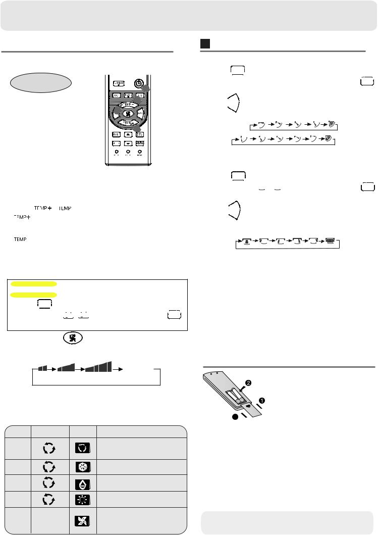
Air Flow Direction Adjustment
1.Status display of air flow
Press 
 button to enter additional options, when
cycle display to 
 ,
, 
 will flash. And then press
 enter to up and down air flow function.
Press 

 button. For each press,changes as follows: Remote controller:
COOL/DRY:
HEAT: |
Initial state |
2.Left and right air flow adjustment
(This function is unavailable on some models.)
Press 
 button to enter additional options, when cycle display to
  ,
,  will flash. And then press
 enter to Left and right air flow function.
Press 

 button. For each press,changes as follows:
Remote controller:
COOL/DRY/HEAT:
Cautions:
 When adjusting the flap by hand,turn off the unit.
 When humidity is high,condensate water might occur
at air outlet if all vertical louvers are adjusted to left or right.
 It is advisable not to keep horizontal flap at downward
position for a long time in COOLor DRY mode , otherwise, condensate water might occur.
Note:
When restart after remote turning off, the remote controller will automatically return to the previous set swing position.
 Loading of the battery
1 Remove the battery cover;
2 Load the batteries as illustrated.
2 R-03 batteries, resetting key (cylinder);

 3 Be sure that the loading 4
  is in line with the" + "/"-";
Load the battery,then put on the cover again.
Note:
 The distance between the signal transmission head and the receiver hole should be within 7m without any obstacle as well.
 When electronic-started type fluorescent lamp or changeover
type fluorescent lamp or wireless telephone is installed in the room, the receiver is apt to be disturbed in receiving the signals, so the distance to the indoor unit should be shorter.
 Full display or unclear display during operation indicates the batteries have been used up. Please change batteries.
 If the remote controller can't run normally during operation, please remove the batteries and reload several minutes later.
Hint:
Remove the batteries in case won't be in use for a long period. If there is any display after taking-out, just press reset key.
2
 Loading...