


OEC UroView 2800

UroView 2800 Periodic Maintenance Procedure
1
Service
Periodic Maintenance
Contents
Schematics
Illustrated Parts
Installation
Contents
General Instructions ........................................................................................................................................................................4
How To Use The Electronic Checklist Form...................................................................................................................................4
Getting Started With the Checklist..................................................................................................................................................4
Safety ................................................................................................................................................................................................5
Ingress Of Water And Solutions .....................................................................................................................................................5
Unauthorized Modifications ............................................................................................................................................................5
Motorized Mechanical Operation....................................................................................................................................................6
Trained Service Personnel .............................................................................................................................................................6
Electrical Shock..............................................................................................................................................................................6
X-radiation Exposure......................................................................................................................................................................7
Required Tools, Test Equipment, and Supplies............................................................................................................................8
Tools...............................................................................................................................................................................................8
Supplies..........................................................................................................................................................................................8
Test Equipment ..............................................................................................................................................................................9
Safety Inspections ...........................................................................................................................................................................9
Remove Power and Covers............................................................................................................................................................9
Mechanical Inspections ................................................................................................................................................................18
Brakes.......................................................................................................................................................................................18
X-ray-Arm..................................................................................................................................................................................18
Tower Mounting ........................................................................................................................................................................18
Electrical Inspections....................................................................................................................................................................20
Electrical Power Cord ...............................................................................................................................................................20
Interconnect Cable....................................................................................................................................................................20
Hand Control and Foot Switches ..............................................................................................................................................20
Table Motion and X-ray Arm Motion Tests................................................................................................................................20
Power On Inspections ..................................................................................................................................................................24
Initialize without Generator .......................................................................................................................................................24
Fans and Filters ........................................................................................................................................................................24
Table Only Initialization.............................................................................................................................................................30
Initialization With Generator......................................................................................................................................................30
Fast Stop...................................................................................................................................................................................31

UroView 2800 Periodic Maintenance Procedure
2
Service
Periodic Maintenance
Contents
Schematics
Illustrated Parts
Installation
Crash and Splash .....................................................................................................................................................................31
Functional Inspection....................................................................................................................................................................32
Imaging Functions ........................................................................................................................................................................32
Image Orientation .....................................................................................................................................................................32
Image Resolution ......................................................................................................................................................................32
Flat Panel Display Video, Shift and PIP....................................................................................................................................33
Remote Workstation Operation.................................................................................................................................................33
Collimator Control .....................................................................................................................................................................34
X-Ray Functions...........................................................................................................................................................................34
Film Exposure ...........................................................................................................................................................................34
Auto Technique Tracking ..........................................................................................................................................................34
High-level Fluoro Indication ......................................................................................................................................................35
Pulsed Image Indication............................................................................................................................................................35
Digital Spot................................................................................................................................................................................36
Low Dose Mode Operation .......................................................................................................................................................36
Beam Alignment Test ...................................................................................................................................................................36
Fluoro Alignment.......................................................................................................................................................................37
Film Alignment ..........................................................................................................................................................................37
Dose Rate.....................................................................................................................................................................................38
Dose Rate (MAX. kV & mA)......................................................................................................................................................38
High Level Fluoro (HLF)............................................................................................................................................................38
Workstation Controls ....................................................................................................................................................................38
Options Testing ............................................................................................................................................................................40
High Capacity Disk Test............................................................................................................................................................40
VCR Test ..................................................................................................................................................................................40
IR Transmitter Test ...................................................................................................................................................................40
Digital Hardcopy Camera test ...................................................................................................................................................40
Instant Film/Paper (Onboard) Printer........................................................................................................................................40
Thermal Printer Test .................................................................................................................................................................41
DICOM ......................................................................................................................................................................................41
Lubrication......................................................................................................................................................................................42
Lift and Tilt Drive...........................................................................................................................................................................42
I.I./X-ray Arm Carriage..................................................................................................................................................................42
Latitudinal Drive............................................................................................................................................................................43
Longitudinal Drive.........................................................................................................................................................................44

UroView 2800 Periodic Maintenance Procedure
3
Service
Periodic Maintenance
Contents
Schematics
Illustrated Parts
Installation
Miscellaneous.................................................................................................................................................................................47
Dose Area Product Calibration.....................................................................................................................................................47
Battery Replacement....................................................................................................................................................................48
Table Maintenance.......................................................................................................................................................................49
Completing the PM.........................................................................................................................................................................50
Reinstall the Covers .....................................................................................................................................................................50
Final Power-On.............................................................................................................................................................................50
PM Checklist Printing ...................................................................................................................................................................50

UroView 2800 Periodic Maintenance Procedure
4
Service
Periodic Maintenance
Contents
Schematics
Illustrated Parts
Installation
General Instructions
This procedure covers the following service intervals:
• Semi-Annual
• Annual
Use this procedure in conjunction with the UroView 2800 Periodic Maintenance (PM) Checklist form. For the Semi-Annual PM, do
only those procedures listed in the Semi-Annual section of the form. For the Annual PM, do all the procedures in both sections.
Within those sections, the procedure names you see on the form correspond to instructions in this procedure document.
How To Use The Electronic Checklist Form
The 2800 Periodic Maintenance Checklist form has been designed using the Microsoft® Word 2000 form tool and should be
completed on-line. The on-line form contains three types of information fields: text/number fields, checkboxes and pull-down
menus.
You can navigate the form using the tab key or by using your mouse. We recommend that you use the mouse. The steps should
be completed in a vertical order. The tab key tabs horizontally.
For text fields, type in the requested information, such as hospital name, etc. For checkboxes, place the mouse cursor on the
checkbox and click. This will place an X in the checkbox. For pull-down menus choose the appropriate selection when it is
displayed and verify that it is present when you close the field.
To make the on-line PM checklist template available to MS Word, save the template in the Microsoft Office Template directory.
Getting Started With the Checklist
Enter the following required information at the top of the form prior to performing the PM test procedures
1. System ID number in the text field.
2. Start Date in the text field.

UroView 2800 Periodic Maintenance Procedure
5
Service
Periodic Maintenance
Contents
Schematics
Illustrated Parts
Installation
3. Read the elapsed time meter on the Workstation and enter the number on the Checklist.
4. Select whether the PM is semi-annual or annual from the pull-down menu.
5. Complete the customer information: Customer Name, Address, etc.
6. Record the following in the Test Equipment block:
A. Test equipment model numbers
B. Test equipment serial numbers
C. Test equipment calibration due date
Note: Test equipment must have current calibration dates. Do not use test equipment with expired calibration stickers.
Safety
Ingress Of Water And Solutions
The system must never be operated or stored in locations where conductive fluids, like water and saline solution, might spill on
the equipment.
Always unplug the AC power cable from the wall outlet before cleaning the equipment. Do not allow water, soap, or other liquids
to drip into the equipment and cause short circuits, electric shock and fire hazards.
Unauthorized Modifications
Under no circumstances should the safety interlock in the system be a bypassed, jumpered, or otherwise disabled.
Note: All GE OEC systems comply with International Electrotechnical Commission safety standard IEC-60601. Do not
connect any external device to the system that does not meet the requirements of IEC-60601. Only devices provided or
approved by GE OEC Medical Systems, Inc. should be connected to the system.

UroView 2800 Periodic Maintenance Procedure
6
Service
Periodic Maintenance
Contents
Schematics
Illustrated Parts
Installation
Motorized Mechanical Operation
The table and X-ray arm are motorized and should be observed continuously during operation to avoid collision with people and
equipment.
If covers are removed, use extreme care when operating motorized features. Do not wear loose clothing that may be caught by
mechanical mechanisms. Keep hands, fingers, hair, or other body parts clear of motorized equipment while the motors are in
operation.
Trained Service Personnel
Serious injury and property damage can result from incorrectly performed service procedures. Observe all operating and safety
procedures discussed in this document.
WARNING: Procedures shall be performed by service personnel specifically trained by GE OEC Medical
Systems, Inc. to calibrate the UROVIEW 2800.
Electrical Shock
WARNING: This system can generate lethal voltages. Practice safe electrical testing procedures when
performing periodic maintenance procedures.
WARNING: After taking X-rays, the high voltage cables can retain a lethal charge, even if you power down
the system. Even though the contacts are recessed, high voltages can arc several inches from
their terminals if the cables are removed from the connector wells. Use caution when
disconnecting high voltage cables even when the power is turned off. If you remove these
connections, immediately discharge their contacts against the high voltage tank case (ground).

UroView 2800 Periodic Maintenance Procedure
7
Service
Periodic Maintenance
Contents
Schematics
Illustrated Parts
Installation
WARNING: Use caution when working near the generator and its connections. Remove metal rings and
watchbands that may inadvertently come in contact with the terminals. Severe skin burns could
result if such metal articles were shorted across the generator input terminals.
X-radiation Exposure
The X-ray tube assembly produces X-radiation when energized. Never operate this device without X-ray shielding in place. Use
lead shielding and draping to protect personnel.
WARNING: Lead aprons, radiation monitors, and appropriate radiation shields must be utilized for the
protection of all personnel in the vicinity while performing tests. Living human anatomy should
never be used as a phantom or demonstration aid. Do not produce radiation in hallways.
CAUTION: Many of the PCB's in this system contain components, which are sensitive to Electro-Static Discharge
(ESD). Observe ESD safety procedures.

UroView 2800 Periodic Maintenance Procedure
8
Service
Periodic Maintenance
Contents
Schematics
Illustrated Parts
Installation
Required Tools, Test Equipment, and
Supplies
Tools
Spline Driver, .048, (00-900921)
High voltage cable wrench
Metric and SAE Allens ( metric set to include half sizes)
Metric and SAE Socket set and or nut drivers (metric set to include half sizes)
Supplies
Alcohol Prep Pads
Laceration Proof Gloves
Safety Glasses
Tungrease (00-902208)
Paint Kit, touchup
Shim, Tower Base, .125SS qty 4 (00-987198-01)
Shim, Tower Base, .250SS qty 4 (00-987198-02)

UroView 2800 Periodic Maintenance Procedure
9
Service
Periodic Maintenance
Contents
Schematics
Illustrated Parts
Installation
Test Equipment
Digital multimeter and probes Light meter
Pausch Serial Extension Cable (81-821528) Converging line pair resolution tool
Digital level (00-902160) Perpendicularity tool (00-874185)
Laptop computer Radiographic Alignment Tool (00-871980)
Film densitometer 3 copper filters (00-877682)
Plexi Glass Phantom Kit (00-884334-01) Static wrist strap (00-800221)
Dosimeter RUS Software (00-884048)
Fiber Optic Kit (00-884422-01) RUS Cable (00-901559)
VGA Monitor00-901163-01 Keyboard00-900598-01
Lemo Socket Tool T-00207
Safety Inspections
Remove Power and Covers
Refer to the illustrations following this page for cover removal.
WARNING: Electrical circuits inside the equipment use voltages that are capable of causing serious injury
or death from electrical shock, even when the Workstation power switch is turned off. Use
appropriate lockout/tag-out precautions.
1. If the system has power applied, place the Workstation power switch in the
OFF
position

UroView 2800 Periodic Maintenance Procedure
10
Service
Periodic Maintenance
Contents
Schematics
Illustrated Parts
Installation
2. At the facility power distribution box, shut off all power, including as applicable 200-208 VAC and 400-480 VAC. Use
lockout/tag-out procedures in compliance with GE OEC safety policies.
3. Separate generator from tower or wall box. Move generator 3 or 4 feet away from tower or wall.
4. Remove the generator covers.
5. Remove the Workstation rear cover, left side cover, and open the electronic card rack rear door.
6. Remove the Tower top and end covers.
7. Remove table movement mechanism covers.
UroView 2800 Periodic Maintenance Procedure
11
Service
Periodic Maintenance
Contents
Schematics
Illustrated Parts
Installation
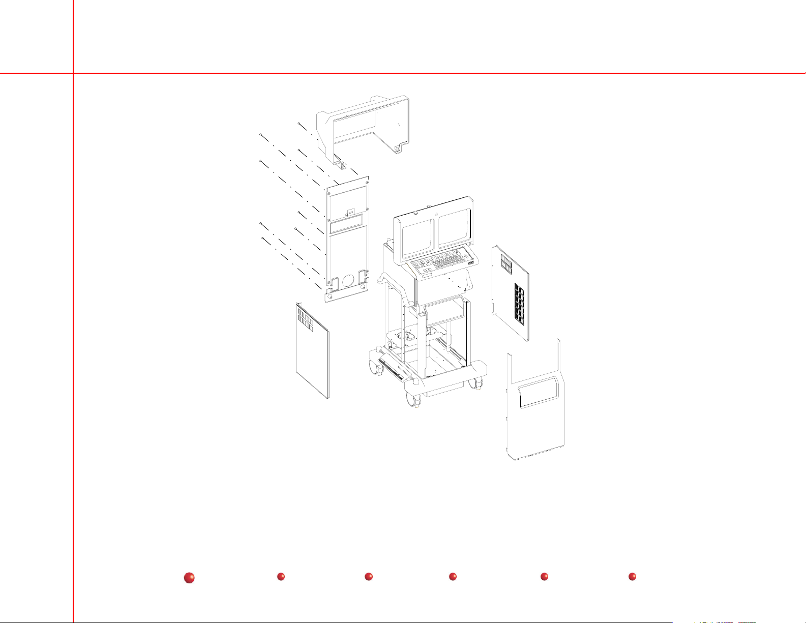
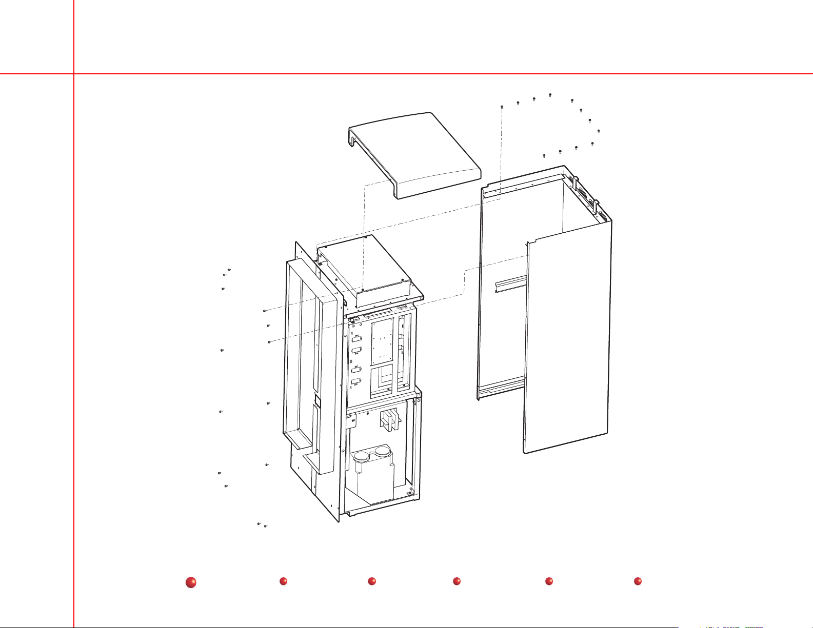
Removing the Workstation Covers
UroView 2800 Periodic Maintenance Procedure
12
Service
Periodic Maintenance
Contents
Schematics
Illustrated Parts
Installation
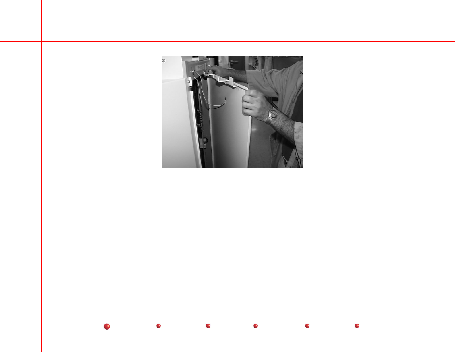
Removing Tower Side Covers
UroView 2800 Periodic Maintenance Procedure
13
Service
Periodic Maintenance
Contents
Schematics
Illustrated Parts
Installation
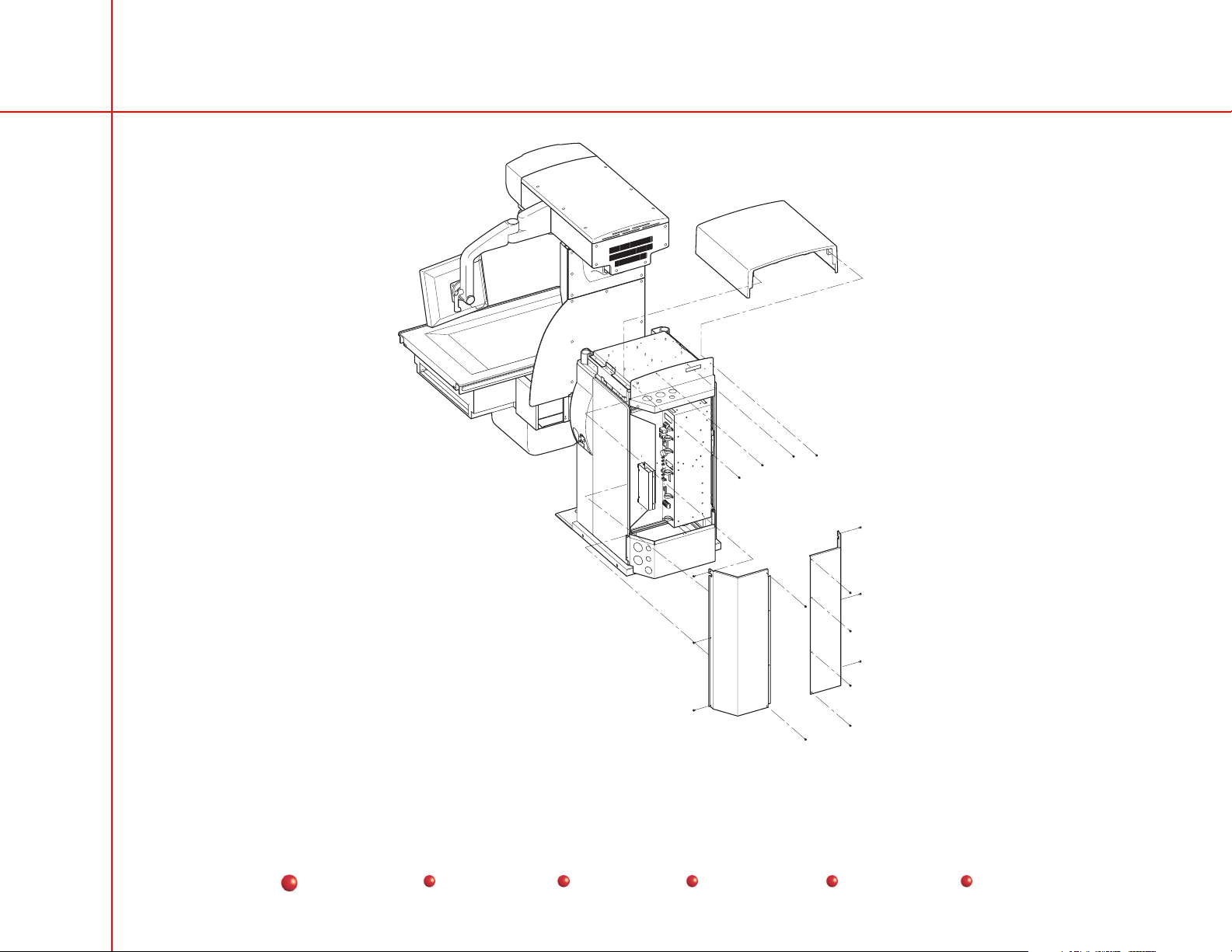
Removing the Tower Top and Upper End Covers
UroView 2800 Periodic Maintenance Procedure
14
Service
Periodic Maintenance
Contents
Schematics
Illustrated Parts
Installation
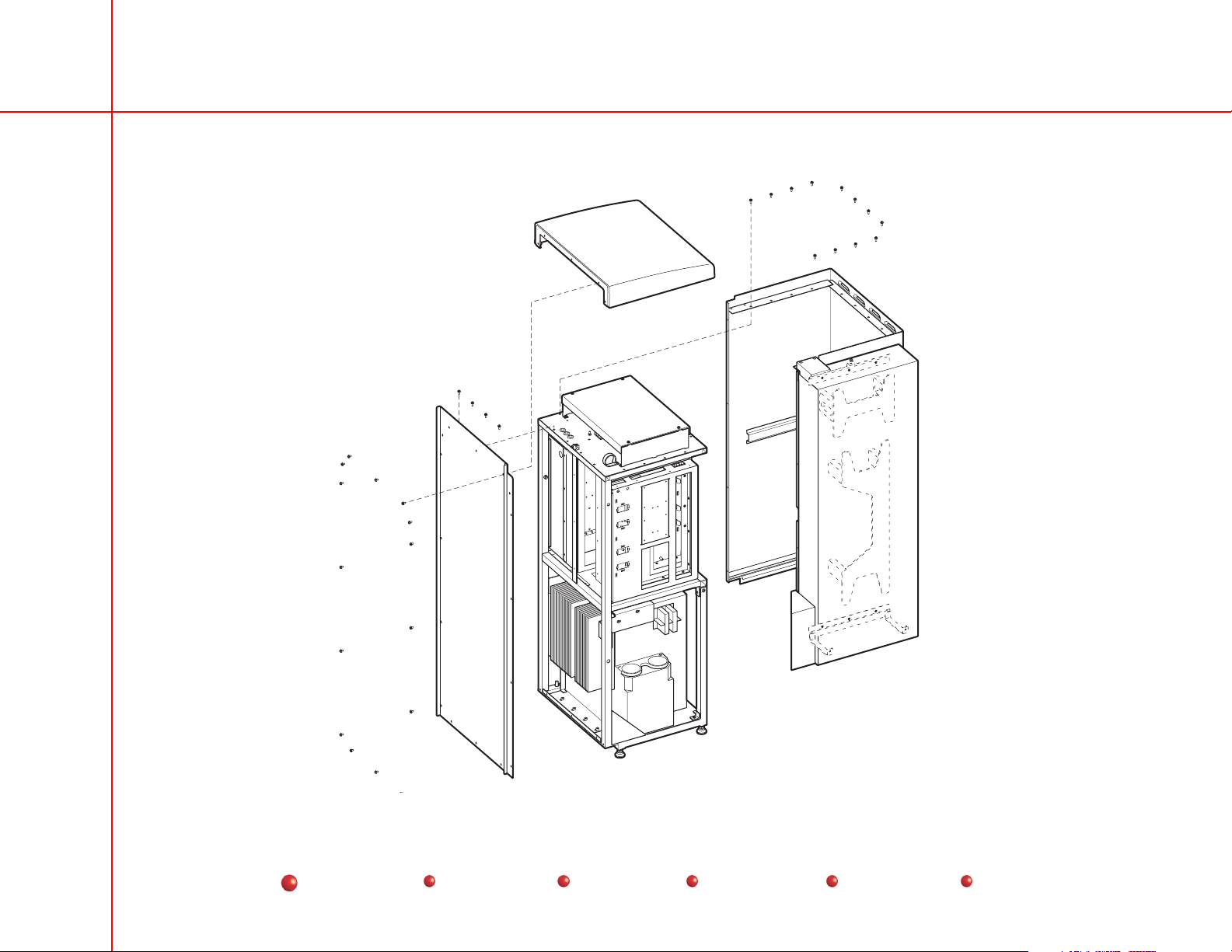
Removing the Generator Covers (Tower Mounted)
UroView 2800 Periodic Maintenance Procedure
15
Service
Periodic Maintenance
Contents
Schematics
Illustrated Parts
Installation
Removing the Generator Covers (Remote Mounted)

UroView 2800 Periodic Maintenance Procedure
16
Service
Periodic Maintenance
Contents
Schematics
Illustrated Parts
Installation
 Loading...