


 Loading...
GE Consumer & Industrial
Multilin
LM10 Motor Protection System
Instruction Manual
LM10 revision: 1.7x
GE publication code: GEK-106642E
GE Multilin part number: 1601-0165-A6 Copyright © 2008 GE Multilin
GE Multilin
215 Anderson Avenue, Markham, Ontario
Canada L6E 1B3
Tel: (905) 294-6222 Fax: (905) 201-2098 Internet: http://www.GEmultilin.com
*1601-0165-A6*
|
|
|
T |
E |
|
|
|
|
|
IS |
R |
||||
|
G |
|
|
||||
R |
E |
|
|
|
|
E |
|
|
|
|
|
|
D |
||
|
|
|
|
|
|
|
|
ISO9001:2000 |
|||||||
E |
|
|
|
|
|
IN |
|
G |
|
|
|
|
L |
||
|
|
|
|
I |
|
||
|
|
MULT |
|
|
|||
GE Multilin's Quality Management System is registered to ISO9001:2000
QMI # 005094
UL # A3775
LM10 MOTOR PROTECTION SYSTEM – INSTRUCTION MANUAL |
1–1 |
© 2008 GE Multilin Incorporated. All rights reserved.
GE Multilin LM10 Motor Protection System instruction manual for revision 1.70. LM10 Motor Protection System, is a registered trademark of GE Multilin Inc.
The contents of this manual are the property of GE Multilin Inc. This documentation is furnished on license and may not be reproduced in whole or in part without the permission of GE Multilin. The content of this manual is for informational use only and is subject to change without notice.
Part numbers contained in this manual are subject to change without notice, and should therefore be verified by GE Multilin before ordering.
Part number: 1601-0165-A6 (March 2008)

1 |
TABLE OF CONTENTS |
Table of Contents
1: INTRODUCTION |
DESCRIPTION ..................................................................................................................... |
1-1 |
|
THE LM10 RELAY ............................................................................................................... |
1-1 |
|
OVERVIEW ........................................................................................................................... |
1-2 |
|
FEATURES ............................................................................................................................. |
1-2 |
|
CURRENT AND VOLTAGE INPUTS ...................................................................................... |
1-2 |
|
RELAY OUTPUTS .................................................................................................................. |
1-2 |
|
POWER SUPPLY ................................................................................................................... |
1-3 |
|
BLOCK DIAGRAM ................................................................................................................. |
1-3 |
|
FEATURES ............................................................................................................................ |
1-4 |
|
PROGRAMMING AND DISPLAY UNIT ................................................................................. |
1-4 |
|
LED INDICATORS ................................................................................................................. |
1-4 |
|
SWITCHES ............................................................................................................................. |
1-4 |
|
ORDERING .......................................................................................................................... |
1-6 |
|
ORDER CODES ..................................................................................................................... |
1-6 |
|
SPECIFICATIONS ................................................................................................................ |
1-7 |
|
PROTECTION ELEMENTS ...................................................................................................... |
1-7 |
|
METERING ............................................................................................................................. |
1-7 |
|
CONTROL FUNCTIONS ........................................................................................................ |
1-8 |
|
INPUTS .................................................................................................................................. |
1-8 |
|
CT DIMENSIONS .................................................................................................................. |
1-10 |
|
OUTPUTS ............................................................................................................................... |
1-10 |
|
COMMUNICATIONS .............................................................................................................. |
1-10 |
|
ENVIRONMENTAL ................................................................................................................. |
1-11 |
|
APPROVALS/CERTIFICATION ............................................................................................... |
1-11 |
|
|
|
2: INSTALLATION |
WIRING ................................................................................................................................ |
2-13 |
|
DEVICENET ........................................................................................................................... |
2-13 |
|
RS232 PORT ....................................................................................................................... |
2-13 |
|
CONTROL TERMINALS ......................................................................................................... |
2-14 |
|
SENSOR PACK INPUT .......................................................................................................... |
2-15 |
|
WIRING DIAGRAM ............................................................................................................... |
2-15 |
|
MOUNTING ......................................................................................................................... |
2-17 |
|
LM10 MOUNTING .............................................................................................................. |
2-17 |
|
PDU DOOR MOUNT ........................................................................................................... |
2-18 |
|
|
|
3: INTERFACE |
PDU OPERATIONS ............................................................................................................. |
3-19 |
|
LIQUID CRYSTAL DISPLAY ................................................................................................... |
3-19 |
|
LEDS ..................................................................................................................................... |
3-19 |
|
KEYPAD ................................................................................................................................. |
3-19 |
|
PDU SCREENS AND MENUS ............................................................................................ |
3-21 |
|
MAIN STARTUP SCREEN ..................................................................................................... |
3-21 |
|
HISTORY RECORD AND STATUS SCREENS ........................................................................ |
3-21 |
|
CONFIGURATION MENU ..................................................................................................... |
3-21 |
|
ENERVISTA LM10 SOFTWARE ........................................................................................ |
3-23 |
|
DESCRIPTION ........................................................................................................................ |
3-23 |
|
FUNCTIONAL DETAILS ......................................................................................................... |
3-23 |
LM10 MOTOR PROTECTION SYSTEM – INSTRUCTION MANUAL |
1–I |

TABLE OF CONTENTS
4: FUNCTIONALITY |
OVERCURRENT FAULT CONDITIONS ............................................................................ |
4-25 |
|
DESCRIPTIONS ...................................................................................................................... |
4-25 |
|
TRIP CURVES EXAMPLE ....................................................................................................... |
4-27 |
|
CONFIGURATION SETTINGS ........................................................................................... |
4-29 |
|
OVERVIEW ............................................................................................................................ |
4-29 |
|
MAIN MENU ......................................................................................................................... |
4-30 |
|
LANGUAGE ............................................................................................................................ |
4-31 |
|
CTS AND CPTS .................................................................................................................... |
4-31 |
|
STARTER TYPE ...................................................................................................................... |
4-32 |
|
RUN 1 AND RUN 2 SETUP ................................................................................................. |
4-32 |
|
TIME DELAYS ........................................................................................................................ |
4-34 |
|
OTHER SETTINGS ................................................................................................................. |
4-34 |
|
AUXILIARY RELAY FAULTS .................................................................................................. |
4-36 |
|
PASSCODE AND LOGIN ....................................................................................................... |
4-37 |
|
RUN OPERATIONS ................................................................................................................ |
4-38 |
|
FACTORY DEFAULT .............................................................................................................. |
4-38 |
|
STATUS VALUES ................................................................................................................. |
4-39 |
|
MAIN MENU ......................................................................................................................... |
4-39 |
|
HISTORY VALUES ............................................................................................................... |
4-41 |
|
LAST TRIP DATA ................................................................................................................... |
4-41 |
|
MOTOR START/STOP LOGIC ........................................................................................... |
4-42 |
|
|
|
5: COMMUNICATIONS |
DEVICENET OPERATIONS ................................................................................................ |
5-45 |
|
DESCRIPTION ........................................................................................................................ |
5-45 |
|
POLL DATA ........................................................................................................................... |
5-45 |
|
IDENTITY OBJECT .................................................................................................................. |
5-47 |
|
MESSAGE ROUTER ............................................................................................................... |
5-47 |
|
DEVICENET OBJECT ............................................................................................................ |
5-47 |
|
ASSEMBLY OBJECT .............................................................................................................. |
5-48 |
|
CONNECTION OBJECT ......................................................................................................... |
5-52 |
|
ACK HANDLER OBJECT ..................................................................................................... |
5-54 |
|
OVERLOAD OBJECT ............................................................................................................. |
5-54 |
|
EXTENSION OBJECT ............................................................................................................. |
5-55 |
|
DATA FORMATS ................................................................................................................... |
5-57 |
|
SPECIAL APPLICATION ......................................................................................................... |
5-61 |
|
SERIAL PORT ....................................................................................................................... |
5-63 |
|
DESCRIPTION ........................................................................................................................ |
5-63 |
|
|
|
6: MISCELLANEOUS |
REVISION HISTORY ........................................................................................................... |
6-65 |
|
RELEASE DATES ................................................................................................................... |
6-65 |
|
CHANGES TO THE MANUAL ................................................................................................ |
6-65 |
|
WARRANTY ......................................................................................................................... |
6-67 |
|
GE MULTILIN WARRANTY .................................................................................................. |
6-67 |
|
|
|
APPENDIX |
DEVICENET OVERVIEW .................................................................................................... |
A-1 |
|
DESCRIPTION ........................................................................................................................ |
A-1 |
|
CONTROLLER AREA NETWORK (CAN) .............................................................................. |
A-2 |
|
DEVICENET OPERATIONS ................................................................................................... |
A-2 |
|
EXPLICIT MESSAGING AND INPUT/OUTPUT (I/O) MESSAGING ..................................... |
A-3 |
|
PRE-DEFINED MASTER/SLAVE CONNECTION SET ........................................................... |
A-3 |
1–II |
LM10 MOTOR PROTECTION SYSTEM – INSTRUCTION MANUAL |

1 |
TABLE OF CONTENTS |
DEVICENET FEATURES ........................................................................................................ |
A-3 |
MAXIMUM CABLE LENGTHS FOR DEVICENET ................................................................. |
A-3 |
DEVICENET SPECIFICATION HIGHLIGHTS ......................................................................... |
A-4 |
LM10 AND GE FANUC 90-30 WITH DEVICENET™ ..................................................... |
A-6 |
OVERVIEW ............................................................................................................................ |
A-6 |
GE FANUC 90-30 PLC HARDWARE ............................................................................... |
A-6 |
NETWORK CONFIGURATION ............................................................................................... |
A-6 |
CONFIGURATION PROCEDURE ........................................................................................... |
A-6 |
POLLING INPUT/OUTPUT CONNECTION ........................................................................... |
A-7 |
COS (CHANGE OF STATE) INPUT/OUTPUT CONNECTION ............................................. |
A-10 |
CYCLIC INPUT/OUTPUT CONNECTION .............................................................................. |
A-10 |
EXPLICIT MESSAGING .......................................................................................................... |
A-11 |
LM10 AND ALLEN-BRADLEY SLC500 VIA DEVICENET™ .......................................... |
A-17 |
DESCRIPTION ........................................................................................................................ |
A-17 |
SYSTEM SETUP ..................................................................................................................... |
A-17 |
INITIAL STEPS ....................................................................................................................... |
A-17 |
SETTING UP THE DEVICENET NETWORK ......................................................................... |
A-17 |
CHANGING THE MODE OF OPERATION ............................................................................ |
A-18 |
CONFIGURING THE SLAVE DEVICE .................................................................................... |
A-19 |
CONTROL AND MONITORING OF THE LM10 .................................................................. |
A-20 |
EXPLICIT MESSAGING WITH THE LM10 RELAY ............................................................... |
A-21 |
DATA TABLE LAYOUT .......................................................................................................... |
A-22 |
LADDER LOGIC ..................................................................................................................... |
A-23 |
INDEX
LM10 MOTOR PROTECTION SYSTEM – INSTRUCTION MANUAL |
1–III |
TABLE OF CONTENTS
1–IV |
LM10 MOTOR PROTECTION SYSTEM – INSTRUCTION MANUAL |

GE Consumer & Industrial
Multilin
LM10 Motor Protection System
Chapter 1: Introduction
1.1Description
1.1.1 The LM10 Relay
The GE Multilin LM10 Motor Protection System is a modular device designed to protect motors from various fault conditions. This device interfaces with a DeviceNet network. The network will monitor and control the relay status and functions. The relay also has the capability of operating in a standalone mode. Configuration can be accomplished via DIP switches on the front of the relay.
Additionally, the relay has an interface port to communicate to the LM10 programming and display unit (PDU). The PDU is a self-contained device consisting of a membrane switch keypad, a liquid crystal display (LCD), and control electronics for communication with the relay. This unit provides a method of configuring and monitoring the LM10. The PDU incorporates an RS232 interface with a proprietary communications protocol.
DeviceNet is a registered trademark of Open DeviceNet Vendor's Association (ODVA).
LM10 MOTOR PROTECTION SYSTEM – INSTRUCTION MANUAL |
1–1 |

OVERVIEW |
CHAPTER 1: INTRODUCTION |
1.2Overview
1.2.1 Features
The LM10 Motor Protection System is a microprocessor-based unit. It takes a ‘snapshot’ image of the three phases of current, one phase of voltage, and ground. The data is then applied to the algorithms and compared to the device's configuration information. Based on the result of the comparison, the relay may trip one or more of the on-board control relays. When applicable, indicators will be illuminated to show the status of the device. Additionally, up to ten trip events will be stored in non-volatile memory.
The LM10 auxiliary communications port to the PDU is an RS232 interface using a standard four-pin RJ11 style cable. This port will allow the PDU to obtain and display any of the real-world data that is contained in the relay as well as to configure the relay.
The LM10 Motor Protection System supports the DeviceNet protocol and can be interfaced with the PLC DeviceNet mastercard or DCS Scanner card. It supports Polled, Change of State (COS), Cyclic I/O Messaging, and Explicit Messaging.
1.2.2Current and Voltage Inputs
The relay has inputs for two sets of three-phase current transformers (CTs) and one ground CT. One set will allow for custom 27 A and 90 A CT sensor packs to be connected; the other will allow for 75 to 800:5 A ratio CTs. Dual speed motors will require two separate CTs connected in parallel.
A 100:1 A core-balance CT or 20 A ground fault sensor pack can be connected to the ground CT terminals for ground current measurement.
Provisions have been made to support various CTs for the three-phase measurements.
Voltage input from the control power transformer (CPT) is conditioned and measured by the analog-to-digital converter to determine supply voltage. This signal, in conjunction with the current, is used to calculate power and power factor.
1.2.3Relay Outputs
The LM10 Motor Protection System contains 4 on-board Form-C relays with NEMA C150 pilot duty ratings. Two relays should be used to control the coils of motor contactor and one to annunciate ground fault status. An additional programmable relay is available for fault status indications.
The two control relays are labeled “RUN 1” and “RUN 2”. These relays are enabled on command from the control logic. If the LM10 detects a fault condition the relays will be deenergize, causing the motors to shut down.
The ground fault relay is energized on detection of a ground fault. Upon correction of the ground fault condition, the relay will be de-energized. The output contact can be used to trip a breaker or annunciate to other devices.
The programmable trip relay is energized when the programmed algorithm conditions have been met and can annunciate out to other devices.
1–2 |
LM10 MOTOR PROTECTION SYSTEM – INSTRUCTION MANUAL |

CHAPTER 1: INTRODUCTION |
OVERVIEW |
1.2.4Power Supply
The LM10 Motor Protection System has an on-board power supply with a fuse that converts the AC input to the levels necessary to operate this device. The operating range is 96 to 140 V AC, nominal 120 V control power (80% to 117%). The supply has programmable auto-restart capability of up to 4 seconds. This also supplies necessary power to the PDU at a TTL.
For correct measurement of power and power factor, the control power must be connected across phase A and phase B of the three-phase power supply.
1.2.5Block Diagram
A single line diagram for the LM10 Motor Protection System is shown below.
FIGURE 1–1: Functional Block Diagram
LM10 MOTOR PROTECTION SYSTEM – INSTRUCTION MANUAL |
1–3 |

FEATURES |
CHAPTER 1: INTRODUCTION |
1.3Features
1.3.1 Programming and Display Unit
The main task of the programming and display unit (PDU) is to provide status information to a local user. The PDU can display the requested parameter(s) on the LCD in either English or Spanish. Additionally, the PDU can be used to configure the LM10 via the RS232 serial communications port.
1.3.2LED Indicators
The LM10 has five (5) LEDs on the front panel. They function as follows:
•Module Status (MS): This two-colored LED is used for the DeviceNet module status. Its function is defined in the DeviceNet specification.
LED State |
Description |
|
|
Off |
No power |
|
|
Green |
Device operational |
|
|
Red |
Unrecoverable fault |
|
|
•Network status (NS): This two-colored LED is used for the DeviceNet network status. Its function is defined in the DeviceNet specification.
LED State |
Description |
|
|
Off |
No power / not online |
Flashing green |
Online, not connected |
|
|
Green |
Link OK, online, connected |
|
|
Flashing red |
Connection timeout |
|
|
Red |
Critical link failure |
|
|
•Overcurrent (OC): This red LED is illuminated when the relay detects an overcurrent condition in one or more of the power phases.
•Ground Fault (GF): This red LED is illuminated when the relay detects a ground fault condition.
•Current Unbalance (CUB): This red LED is illuminated when the relay detects a current unbalance between the power phases.
1.3.3Switches
The following switches are located on the front panel of the LM10. Changes to switch settings will not take effect until power is cycled (on-off).
All other relay features (e.g., the CT sensor pack) can only be programmed via DeviceNet or the RS232 configuration port.
•MAC ID: Two rotary DIP switches are used to set the DeviceNet MAC ID. Each unit on the DeviceNet network requires a unique MAC ID. The valid ID range is from 0 to 63, with a factory default of 0. Cycle power after any switch changes.
1–4 |
LM10 MOTOR PROTECTION SYSTEM – INSTRUCTION MANUAL |
CHAPTER 1: INTRODUCTION |
FEATURES |
•Baud rate: This two-position DIP switch is used to select the DeviceNet baud rate. The valid rates are 125K, 250K and 500K bits per second. The DIP switch is defaulted to 125K baud rate when shipped.
Baud Rate |
DIP Switch Position |
|
|
125 kbps |
down - down |
|
|
250 kbps |
up - down |
|
|
500 kbps |
up - up |
|
|
Changes to switch settings will not take effect until the next power cycle.
•Trip Class (TC): NEMA overload trip class is selected using a rotary DIP switch. Valid settings are Class 10, 15, 20, or 30. To set the trip class, align the screwdriver slot with the desired value. Do not use the triangle marker on the DIP switch. A screwdriver with a nominal blade width of 0.094 to 0.175 inches should be used. Smaller blades could allow the switch to be set in an invalid position.
Changes to switch settings will not take effect until power is cycled.
Display
Liquid crystal display: four lines of 16 characters per line.
Status
The status sub-menu can display current, motor status, Run 1 and Run 2 data, faults, MAC ID, baud rate, and overload class.
Reset
The relay can be reset from the PDU, pushbutton, or the LAN.
Mounting Flexibility
The relay can be attached to the PDU without hardware to facilitate door mounting.
LEDS
One green LED power indicator and a flashing red trip LED to indicate over/undercurrent, current unbalance, ground fault, under/overvoltage, and trip command.
CONFIG
The relay parameters are programmed via the CONFIG button. The CONFIG sub-menu is similar to the status menu, and allows the user to change relay parameters: CT ratio, PT ratio, fault settings, and time delays.
History
Displays the last ten (10) trip records. The conditions at the time of fault are displayed and can be scrolled through using the UP/DOWN arrow keys.
849713A3.CDR
FIGURE 1–2: LM10 Features
LM10 MOTOR PROTECTION SYSTEM – INSTRUCTION MANUAL |
1–5 |

ORDERING |
CHAPTER 1: INTRODUCTION |
1.4Ordering
1.4.1 Order Codes
The order codes for the LM10 Motor Protection System are shown below.
Table 1–1: LM10 Order Codes
|
LM10 |
D* |
CT** |
GF** |
C* |
** |
|
Base unit |
LM10 |
| |
| |
| |
| |
| |
LM10 Motor Protection System |
Programmable |
|
X |
| |
| |
| |
| |
No display unit |
display unit |
|
1 |
| |
| |
| |
| |
Programmable display unit (with |
|
|
|
|
|
|
|
cable) |
Thermal overload |
|
XX |
| |
| |
| |
No phase current transformer |
|
current transformer |
|
01 |
| |
| |
| |
Current sensor, NEMA starter size |
|
|
|
|
|
|
|
|
1, 3-phase, 27 A |
|
|
|
02 |
| |
| |
| |
Current sensor, NEMA starter size |
|
|
|
|
|
|
|
2 and 3, 3-phase, 90 A |
|
|
|
03 |
| |
| |
| |
Current sensor, NEMA starter size |
|
|
|
|
|
|
|
4, 3-phase, 200 A |
|
|
|
04 |
| |
| |
| |
Current sensor, NEMA starter size |
|
|
|
|
|
|
|
5, 1-phase, 300 A |
|
|
|
05 |
| |
| |
| |
Current sensor, NEMA starter size |
|
|
|
|
|
|
|
6, 1-phase, 600 A |
Ground fault sensor |
|
|
XX |
| |
| |
No ground fault sensor |
|
|
|
|
|
01 |
| |
| |
Ground fault sensor: 20 A, 0.44" |
|
|
|
|
|
|
|
window |
|
|
|
|
02 |
| |
| |
Ground fault sensor: 20 A, 1.56" |
|
|
|
|
|
|
|
window |
|
|
|
|
03 |
| |
| |
Ground fault sensor: 20 A, 2.08" |
|
|
|
|
|
|
|
window |
|
|
|
|
04 |
| |
| |
Ground fault sensor: 20 A, 2.50" |
|
|
|
|
|
|
|
window |
|
|
|
|
05 |
| |
| |
Ground fault sensor: 20 A, 3.31" |
|
|
|
|
|
|
|
window |
|
|
|
|
06 |
| |
| |
Ground fault sensor: 20 A, 4.62" |
|
|
|
|
|
|
|
window |
Cable |
|
|
|
|
X |
| |
No cable |
|
|
|
|
|
1 |
| |
30-inch communication cable |
|
|
|
|
|
|
|
from relay to PC |
Reserved |
|
|
|
|
|
XX |
For future use |
|
|
|
|
|
|
|
|
1–6 |
LM10 MOTOR PROTECTION SYSTEM – INSTRUCTION MANUAL |

CHAPTER 1: INTRODUCTION SPECIFICATIONS
1.5 |
Specifications |
|
|
1.5.1 Protection Elements |
|
|
OVERCURRENT (ANSI 51) |
|
|
Curve shapes: .................................................. |
NEMA class 10, 15, 20 and 30, hot and cold |
|
Timing accuracy:............................................ |
±5% of total trip time + 1 second |
|
GROUND FAULT |
|
|
Pickup level: ..................................................... |
0.4 to 20.0 A in steps of 0.2 |
|
Pickup accuracy: ............................................ |
±5% or ±0.1 A, whichever is greater |
|
Time delay:........................................................ |
0 to 2.5 seconds in steps of 0.1 |
|
Timing accuracy:............................................ |
±200 ms |
|
CURRENT UNBALANCE (ANSI 46) |
|
|
Pickup level: ..................................................... |
2 to 25% in steps of 1 |
|
Pickup accuracy: ............................................ |
±5% |
|
Time delay:........................................................ |
0 to 255 seconds in steps of 1 |
|
Timing accuracy:............................................ |
±5% of total trip time + 1 second |
|
MECHANICAL JAM |
|
|
Pickup level: ..................................................... |
100 to 250% in steps of 1 |
|
Pickup Accuracy: ............................................ |
±5% |
|
Time delay:........................................................ |
0 to 1000 seconds in steps of 5 |
|
Timing accuracy:............................................ |
±5% of total trip time + 1 second |
|
STALL |
|
|
Pickup level: ..................................................... |
330 to 600% in steps of 5 |
|
Pickup Accuracy: ............................................ |
±5% |
|
Time delay:........................................................ |
0 to 30.0 seconds in steps of 0.5 |
|
Timing accuracy:............................................ |
±5% of total trip time + 1 second |
|
LOAD LOSS |
|
|
Pickup level: ..................................................... |
15 to 100% in steps of 1 |
|
Pickup Accuracy: ............................................ |
±5% |
|
Time delay:........................................................ |
0 to 255 seconds in steps of 1 |
|
Timing accuracy:............................................ |
±5% of total trip time + 1 second |
UNDERVOLTAGE/OVERVOLTAGE
Undervoltage pickup level: 80% of nominal voltage (96 V)
Overvoltage pickup level: 117% of nominal voltage (140 V)
Pickup accuracy: ............................................ |
±5% |
Trip time:............................................................. |
0.5 second |
Timing accuracy:............................................ |
±200 ms |
1.5.2Metering
PHASE CURRENT
Resolution: ......................................................... |
0.1 A |
Range:.................................................................. |
0.05 to 8 × CT Primary (3200.0 A max.) |
Accuracy: ........................................................... |
±5% of full scale |
LM10 MOTOR PROTECTION SYSTEM – INSTRUCTION MANUAL |
1–7 |
SPECIFICATIONS CHAPTER 1: INTRODUCTION
AVERAGE CURRENT
Resolution: ......................................................... |
0.1 A |
Range:.................................................................. |
0.05 to 8 × CT Primary (3200.0 A max.) |
Accuracy:............................................................ |
±5% of full scale |
GROUND CURRENT |
|
Resolution: ......................................................... |
0.1 A |
Range:.................................................................. |
0.0 to 25.0 A |
Accuracy:............................................................ |
±0.2A when current < 4.0 A |
|
±5% of full scale when current ≥ 4.0A |
CURRENT UNBALANCE |
|
Resolution: ......................................................... |
1% |
Range:.................................................................. |
0 to 250% |
Accuracy:............................................................ |
±5% of full scale |
VOLTAGE |
|
Resolution: ......................................................... |
1 V |
Range:.................................................................. |
0 to 9000 V |
Accuracy:............................................................ |
±5% of full scale |
POWER |
|
Resolution: ......................................................... |
0.1 kW |
Range:.................................................................. |
0 to 6553.5 kW |
Accuracy:............................................................ |
±5% of full scale |
POWER FACTOR |
|
Resolution: ......................................................... |
0.01 |
Range:.................................................................. |
0.5 to 1.0 |
Accuracy:............................................................ |
±5% of full scale |
TRIP HISTORY |
|
Trip history:........................................................ |
up to last 10 trips |
COUNTERS |
|
Motor run hour counter: ............................. |
up to 65535 hours |
1.5.3 Control Functions
STARTER
Starter types:.................................................... |
FVNR, FVR, RV, 2S1W, 2S2W, custom |
Power loss autorestart: ............................... |
restart after power loss of 4 seconds or less |
1.5.4Inputs
POWER SUPPLY
Control power: ................................................. |
80 to 145 V AC |
Frequency:......................................................... |
50 and 60Hz |
CURRENT |
|
CT sensor pack: ............................................... |
NEMA starter size 1 to 6 (27 A, 90 A primary) |
Sensor Input:..................................................... |
0 to 0.27 V AC |
Phase CT input:................................................ |
0 to 5 A |
Phase CT primary: .......................................... |
75, 100, 120, 150, 200, 225, 250, 300, 400, 500, 600, 700, |
|
800 |
1–8 |
LM10 MOTOR PROTECTION SYSTEM – INSTRUCTION MANUAL |

CHAPTER 1: INTRODUCTION SPECIFICATIONS
Ground CT input:............................................. |
20 A ground fault sensor or 20:0.2 A ground fault CT |
VOLTAGE |
|
PT secondary:................................................... |
0 to 120 V |
PT primary: ........................................................ |
200 to 7200 V |
CONTACT INPUT |
|
Inputs:.................................................................. |
7 fixed inputs (Run 1, Run 2, Aux sense 1, Aux sense 2, |
|
Stop, Reset, DeviceNet control) |
Recommended Supply voltage: .............. |
100 to 135 V AC |
When the LM10 contact inputs are connected to the remote devices for the input signal via long cables, induced voltages may be present at the input terminal of LM10 relay. The contact input status could be detected as closed if the induced voltages are greater than 33V. Under these situations it is recomonded to use interposing relay or to connect a resistor across the LM10 contact input terminal and ground to provide path for the induced voltages to the ground.
LM10 MOTOR PROTECTION SYSTEM – INSTRUCTION MANUAL |
1–9 |
SPECIFICATIONS |
CHAPTER 1: INTRODUCTION |
1.5.5CT Dimensions
Thermal overload CT
Order Code |
Description |
Window |
Overall Dimensions |
|
|
Diameter |
|
|
|
|
|
|
Current Sensor, NEMA |
|
|
CT01 |
Starter Size 1, 3 phase, |
0.44" |
4.625"x2.000"x1.375" |
|
27 amp |
|
|
|
|
|
|
|
Current Sensor, NEMA |
|
|
CT02 |
Starter Size 2&3, 3 phase, |
0.44" |
4.625"x2.000"x1.375" |
|
90 amp |
|
|
|
|
|
|
|
Current Sensor, NEMA |
|
|
CT03 |
Starter Size 4, 3 phase, |
0.69" |
5.60"x2.38"x1.72" |
|
200 amp |
|
|
|
|
|
|
|
Current Sensor, NEMA |
|
|
CT04 |
Starter Size 5, 1 phase, |
1.50" |
4.50"x4.88"x4.68" |
|
300 amp |
|
|
|
|
|
|
|
Current Sensor, NEMA |
|
|
CT05 |
Starter Size 6, 1 phase, |
2.50" |
4.57"x4.57"x4.68" |
|
600 amp |
|
|
|
|
|
|
Ground fault CT
Order Code |
Description |
Window |
Overall Dimensions |
|
|
|
Diameter |
|
|
|
|
|
|
|
GF01 |
Ground Fault Sensor 1&2, |
0.44" |
4.625"x2.000"x1.375" |
|
20 amp, 3x 0.44" windows |
||||
|
|
|
||
|
|
|
|
|
GF02 |
Ground Fault Sensor 3&4, |
1.56" |
3.53"x3.65"x2.23" |
|
20 amp, 1x 1.56" window |
||||
|
|
|
||
|
|
|
|
|
GF03 |
Ground Fault Sensor 5, |
2.08" |
9.00"x3.94"x2.23" |
|
20 amp, 3x 2.08" windows |
||||
|
|
|
||
|
|
|
|
|
|
Ground Fault Sensor, Limit |
|
|
|
GF04 |
Amp, |
2.5" |
4.57"x4.57"x4.68" |
|
|
20 amp, 1x 2.5" window |
|
|
|
|
|
|
|
|
|
Ground Fault Sensor, Limit |
|
|
|
GF05 |
Amp, |
3.13" |
4.63"x5.10"x5.50" |
|
|
20 amp, 1x 3.13" window |
|
|
|
|
|
|
|
|
|
Ground Fault Sensor, Limit |
|
|
|
GF06 |
Amp, |
4.62" |
7.00"x7.12"x6.82" |
|
|
20 amp, 1x 4.62" window |
|
|
|
|
|
|
|
1.5.6 Outputs |
|
RELAY OUTPUTS |
|
Relay pilot duty:............................................... |
5 A at 120 V AC |
|
5 A at 28 V DC |
1.5.7 Communications
DEVICENET
Functionality:.................................................... |
group 2 slave only |
Device type:....................................................... |
motor starter |
1–10 |
LM10 MOTOR PROTECTION SYSTEM – INSTRUCTION MANUAL |

CHAPTER 1: INTRODUCTION SPECIFICATIONS
|
Connector type:............................................... |
5-pin micro-style molded male connector |
|
Baud rate: .......................................................... |
125, 250 and 500 kbps via DIP switches |
|
Mac id: ................................................................. |
0 to 63 via DIP switches |
|
Supports: ............................................................ |
Poll, COS and Cyclic IO, and explicit messaging |
|
LEDs:..................................................................... |
network status and device status |
|
SERIAL COMMUNICATIONS |
|
|
Serial port: ......................................................... |
RJ11 4-pin connector for Enervista LM10 Setup software |
|
|
or to PDU |
|
PANEL DISPLAY UNIT (OPTIONAL) |
16 character × 4 line display |
|
Display:................................................................ |
|
1.5.8 |
Environmental |
|
|
AMBIENT TEMPERATURE |
|
|
Operating temperature:.............................. |
0 to 60°C |
|
Storage temperature:................................... |
–30 to 80°C |
|
HUMIDITY |
|
|
Humidity:............................................................ |
up to 95% non condensing |
1.5.9 |
Approvals/Certification |
|
|
CERTIFICATION |
|
|
UL: ........................................................................ |
file number E228903 listed for USA and Canada |
|
CE:.......................................................................... |
conforms to EN 55011, EN 61000, IEC 68-2 |
|
DeviceNet CONFORMANCE TESTED™ |
|
LM10 MOTOR PROTECTION SYSTEM – INSTRUCTION MANUAL |
1–11 |
SPECIFICATIONS |
CHAPTER 1: INTRODUCTION |
1–12 |
LM10 MOTOR PROTECTION SYSTEM – INSTRUCTION MANUAL |

GE Consumer & Industrial
Multilin
LM10 Motor Protection System
Chapter 2: Installation
2.1Wiring
2.1.1 DeviceNet
The LM10 has one micro-style (Brad Harrison style) connector that allows the purchase of pre-built cables for attachment to the unit and the ability to daisy chain from one unit to the next. These connectors meet all DeviceNet physical layer requirements.
FIGURE 2–1: LM10 DeviceNet Pinout
2.1.2RS232 Port
The RS232 configuration port uses a standard RJ11 connector to interface with the programming and display unit (PDU) or with a computer. Both communication and power will be provided to the PDU through this connection. Standard RS232 levels are used for the communications.
RJ11 Pin |
Description |
|
|
1 |
N/A |
|
|
2 |
Ground |
|
|
3 |
TXD |
|
|
4 |
RXD |
|
|
LM10 MOTOR PROTECTION SYSTEM – INSTRUCTION MANUAL |
2–13 |

WIRING |
|
CHAPTER 2: INSTALLATION |
|
|
|
|
|
|
RJ11 Pin |
Description |
|
|
|
|
|
|
|
|
|
|
5 |
+5 V (PDU use only) |
|
|
|
|
|
|
6 |
N/A |
|
|
|
|
|
The LM10 base unit and PDU are designed to use a maximum 36-inch cable when the PDU is mounted door-mounted alone. A shorter cable can be used when the two units are doormounted together.
The connection for the RS232 serial communications port is shown in the following figure. The EnerVista LM10 software can be used to configure and monitor the status of the LM10 through the RS232 port.
FIGURE 2–2: LM10 RS232 Pinout
2.1.3Control Terminals
The control terminal block is a phoenix contact style 0.2-inch center, dual-row, 16 points per row removable connector. The connector will be used to make all field connections (other than communications and CT sensors) to the unit. The terminal block has the following connections:
Table 2–1: Control Connections
|
Upper Signal Row |
|
|
1 |
120 V AC - phase 1 |
|
|
2 |
120 V AC - phase 2 |
|
|
3 |
Switch input - stop |
|
|
4 |
Switch input - reset |
|
|
5 |
Switch input - common |
|
|
6 |
Relay 1 N.O. - run |
|
|
7 |
Relay 1 common - run |
|
|
8 |
Chassis ground |
|
|
9 |
Relay 2 N.O. - run |
|
|
10 |
Ground fault relay N.C. |
|
|
11 |
Relay 2 common - run |
|
|
12 |
5 A CT 1 phase B |
|
|
13 |
5 A CT 1 phase A |
|
|
14 |
5 A CT 1 phase C |
|
|
15 |
5 A CT 1 common |
|
|
16 |
Ground CT 1 |
|
|
|
Lower Signal Row |
|
|
17 |
Switch input - auxiliary 2 |
|
|
18 |
Switch input - auxiliary 1 |
|
|
19 |
Switch input - run 2 |
|
|
20 |
Switch input - run 1 |
|
|
21 |
Switch input - DeviceNet control |
|
|
22 |
Ground fault relay N.O. |
|
|
23 |
Ground fault relay common |
|
|
24 |
Programmable relay N.O. |
|
|
25 |
Programmable relay N.C. |
|
|
26 |
Programmable relay common |
|
|
27 |
5 A CT 2 phase B |
|
|
28 |
5 A CT 2 phase A |
|
|
29 |
5 A CT 2 phase C |
|
|
30 |
5 A CT 2 common |
|
|
31 |
No connection |
|
|
32 |
Ground CT 2 |
|
|
2–14 |
LM10 MOTOR PROTECTION SYSTEM – INSTRUCTION MANUAL |
CHAPTER 2: INSTALLATION |
WIRING |
FIGURE 2–3: LM10 Control Signal Contacts
Service hint: Remove the bottom terminal block first, using a small screwdriver in either end. The top terminal block can then be removed using a coin or any broad-blade tool.
2.1.4Sensor Pack Input
Connectors S1 and S2 are used to connect to all CT Sensor Packs. 5 A CTs connect via the
Phoenix terminal block.
S1/S2 Pins |
Description |
|
|
1 |
CT phase A |
2 |
CT phase B |
|
|
3 |
CT phase C |
|
|
4 |
CT phase A common |
|
|
5 |
CT phase B common |
|
|
6 |
CT phase C common |
|
|
2.1.5Wiring Diagram
A typical LM10 wiring diagram is shown below. The relay should be programmed as “Maintained Off” (under “Other Settings”) for momentary start input. See page 4–34 for additional details.
LM10 MOTOR PROTECTION SYSTEM – INSTRUCTION MANUAL |
2–15 |

WIRING |
CHAPTER 2: INSTALLATION |
FIGURE 2–4: LM10 Wiring Diagram
2–16 |
LM10 MOTOR PROTECTION SYSTEM – INSTRUCTION MANUAL |

CHAPTER 2: INSTALLATION |
MOUNTING |
2.2Mounting
2.2.1 LM10 Mounting
Three mounting options are available.
1.The relay has four holes in the back to allow securing to a mounting plate with screws by others.
2.When mounted in a GE Evolution Series E9000 Motor Control Center, a mounting bracket (provided separately by GE) has been designed to suspend the LM10 base unit inside the MCC bucket. To install, first remove the plastic mounting plate from the LM10.
3.Front door mounting feature (see PDU Door Mount on page 2–18).
MCC hint: Grasp the bottom of the LM10 in one hand, and slide in opposite directions to detach. Attach the mounting plate to the bracket provided using four (4) screws (not included). Once the mounting bracket and plate are installed, slide the LM10 base unit back onto the plate.
FIGURE 2–5: LM10 Base Unit Dimensions
LM10 MOTOR PROTECTION SYSTEM – INSTRUCTION MANUAL |
2–17 |
MOUNTING |
CHAPTER 2: INSTALLATION |
FIGURE 2–6: LM10 Backplate Dimensions
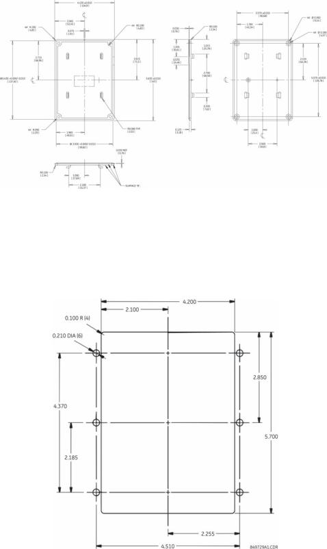
2.2.2PDU Door Mount
The PDU can be door-mounted using the gasket and six screws provided. The rear of the unit protrudes through a cutout and is accessible from inside the door. Recommended cutout dimensions and screw hole locations are shown below.
FIGURE 2–7: PDU Door-mount Dimensions
2–18 |
LM10 MOTOR PROTECTION SYSTEM – INSTRUCTION MANUAL |

GE Consumer & Industrial
Multilin
LM10 Motor Protection System
Chapter 3: Interface
3.1PDU Operations
3.1.1 Liquid Crystal Display
The liquid crystal display is a 5 × 8 font pixelized character type in a 16-character by 4-line format. A yellow-green background offers good readability under direct sunlight and normal room lighting. The display is reflective, not backlit. Display messages can be changed to Spanish.
3.1.2LEDs
A green LED power indicator and a flashing red LED fault indicator is provided. The green power indicator flashes when in the Configuration mode, and the flashing red LED indicates a trip condition.
3.1.3Keypad
The keypad consists of seven buttons used to view and select menu items displayed on the LCD. The keypad is for program changes and data display. With the exception of testing, the PDU is not a control keypad.
•Up and down arrows: At the main configuration screen, the up and down arrows control the LCD contrast level. At all other screens, they are used to scroll through a list or increase/decrease selected values.
•Enter: At the main configuration screen, pressing the Enter button toggles the LCD display from English to Spanish. Pressing again will return the display to English. The Enter button is used to make a selection.
•History: Pressing the History button displays the last ten (10) fault history records. Each history record contains a snapshot of conditions when the unit last faulted. The following items are displayed: fault type, phase currents, ground current, voltage,
LM10 MOTOR PROTECTION SYSTEM – INSTRUCTION MANUAL |
3–19 |
PDU OPERATIONS |
CHAPTER 3: INTERFACE |
power factor, kW, average current, and current unbalance. Pressing the History button again advances to the next history record.
•Status: Pressing the Status button displays the current conditions of the LM10. The following items are displayed: phase currents, ground current, voltage, kW, power factor, average current, current unbalance, and elapsed motor hours.
•Config.:In User mode (default startup condition, no passcode entered), pressing the Config. button displays the following programmed parameters: English or Spanish display, CTs and CPTs, starter type, Run 1 setup, Run 2 setup, time delays, other settings, auxiliary relay faults, and passcode/login.
In Configuration mode (after proper passcode entered), the same Config screens are available to edit. In addition, the following restricted-access options are displayed: run operations and restore factory default configuration.
•Reset: At the main startup screen, the Reset button clears fault conditions, thereby allowing the motor to be ready to restart. At all other screens, pressing the Reset button brings the previous menu.
3–20 |
LM10 MOTOR PROTECTION SYSTEM – INSTRUCTION MANUAL |

CHAPTER 3: INTERFACE |
PDU SCREENS AND MENUS |
3.2PDU Screens and Menus
3.2.1 Main Startup Screen
The main startup screen displays the following information. These parameters are not programmable via serial communications, but rather are displayed for convenience. See Switches on page 1–4 for setting instructions.
•PDU software version displayed briefly, then replaced by the LM10 software version
•Trip class
•MAC ID
•Baud rate
3.2.2History Record and Status Screens
See Keypad on page 3–19 for details on the history record and status screens.
3.2.3Configuration Menu
See Keypad on page 3–19 for details on the configuration menu list. The configuration menu is used to set all the programmable parameters outlined in Configuration Settings on page 4–29.
•CTs and CPTs Sub-menu: This menu and its sub-menus are used to select Control Power Transformer (CPT), Current Transformer (CT) or Sensor Pack, and the number of turns through the CT.
•Starter Type Sub-menu: This menu is used to select Motor Starter Type.
•Run 1 and Run 2 Setup Sub-menus: This Run 1 menu is used to set full load current (FLA) for Run 1. It also contains sub-menus for enable/disable and configures the following optional faults: ground fault, jam, stall, current unbalance, and load loss.
Each fault is configurable not only in magnitude, but also in time delay in which that condition is allowed to exist before the LM10 trips.
The Run 2 Setup menu is laid out identically to Run 1 menu. Unless a custom motor type is selected, Run 2 setup is not necessary.
The full-load current will auto-populate if “Two-Speed” is selected. 2S1W will provide a 4:1 ratio of the FLA and 2S2W will set the FLA to a 2:1 ratio.
Only one relay at a time can be on.
• Time Delays Sub-menu: The following time delays are set using this menu:
Auxiliary sense 1 (contactor closed; opened detects welded contacts)
Auxiliary sense 2 (contactor closed; opened detects welded contacts)
Run 1 to Run 2 (delay between forward and reverse or between speeds)
LM10 MOTOR PROTECTION SYSTEM – INSTRUCTION MANUAL |
3–21 |
PDU SCREENS AND MENUS |
CHAPTER 3: INTERFACE |
Run 2 to Run 1 (delay between forward and reverse or between speeds)
•Other Settings Sub-menu: The Other Settings menu is used to enable/disable the following: under/overvoltage, maintained vs. momentary switches, auto restart, DeviceNet fault, and 50 vs. 60 Hz system. It is also used to select the data grouping which is read through DeviceNet polling and to reset elapsed time meter. See Chapter 4 for details.
•Auxiliary Relay Faults Sub-menu: The auxiliary or programmable relay can be triggered upon any or all of the following fault conditions: overcurrent, jam, stall, current unbalance, auxiliary sense fault, load loss, power failure, DeviceNet fault, and under/overvoltage.
•Passcode, Login Screen: The unit has three passcode levels – User, Configurator, and Calibrator (shown as "change" on the PDU display). The default condition is User mode. It is necessary to login as Configurator in order to change any parameters. The unit is not meant for field calibration, therefore Calibration mode shall not be discussed in this Guide.
To enter a passcode press Config. and scroll down to the Pass Code field. Press enter to select, then use the up/down arrows to scroll to Config: press enter again to login. An incorrect passcode will force the login back to User.
The default Configurator passcode is “0” and can only be changed when in the Config mode. The menu item to change the passcode will become active after a successful login attempt. The Pass Code is a numeric value between 0 and 65535.
•Run Operations Screen: Press in Config. Mode and scroll down to Run Operation, this screen allows control of the Run, Stop, and Reset commands via the PDU. It may be used for test purposes.
•Restore Factory Configuration Screen: This screen, available only to Configurator or higher login, resets all parameters to factory defaults. The PDU will prompt the user to confirm the request prior to resetting parameters. Default settings are listed in Table 3 Configuration Parameters.
3–22 |
LM10 MOTOR PROTECTION SYSTEM – INSTRUCTION MANUAL |
CHAPTER 3: INTERFACE |
ENERVISTA LM10 SOFTWARE |
3.3EnerVista LM10 Software
3.3.1 Description
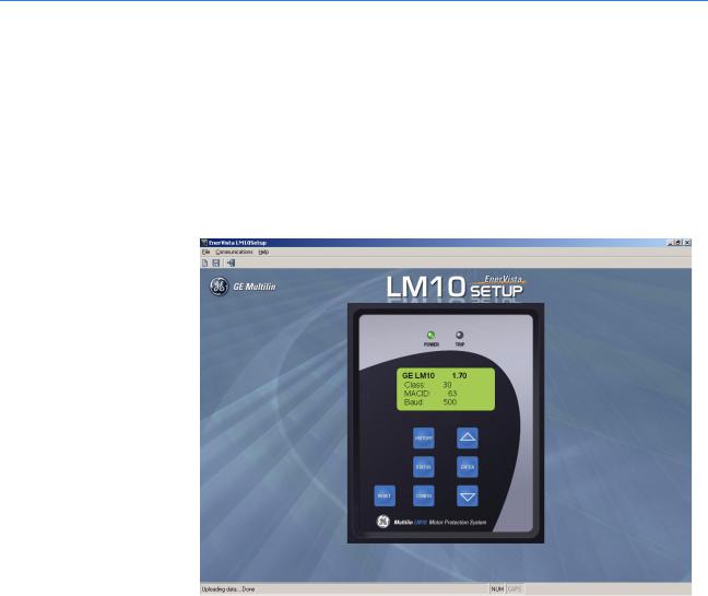
The EnerVista LM10 software is intended as an interface to the GE Multilin LM10 Motor Protection System. It has all the capabilities of the GE Multilin LM10 Motor Protection System, although some of the operations may differ slightly. The major difference is configuration parameters are not directly changed from the PDU screen, they must be downloaded after modifying. Also data values can be entered directly with the keyboard digits.
FIGURE 3–1: Main software screen
3.3.2Functional Details
The EnerVista LM10 software has three menus: File, Communication and Help.
The File menu has following submenu items:
•New: Loads the memory with default values for the LM10 configuration parameters.
•Load: Loads the selected file and restores the LM10 configuration and communication parameters from the file.
•Save: Saves the LM10 configuration and communication parameters to the selected or entered file.
•Exit: Closes the program.
The Communication menu has the following submenu items:
LM10 MOTOR PROTECTION SYSTEM – INSTRUCTION MANUAL |
3–23 |
ENERVISTA LM10 SOFTWARE |
CHAPTER 3: INTERFACE |
•Download: Sends the configuration parameters from memory to the connected LM10. Note that you must be logged into the LM10 as a configurator to download configuration parameters.
•Upload: Gets the configuration parameters from the connected LM10 and saves them in memory.
•Port: Shows the available communications ports. The current selected COM port is indicated by a check mark. The green power LED indicates that communication is currently established with the LM10.
The Help menu has following submenu items:
•Manual: Opens the enerVista LM10 setup software help file.
•About: Displays the enerVista LM10 setup software version and information.
The EnerVista LM10 software uses hot keys for the following that equate to a mouse click on the PDU keys.
Table 3–1: EnerVista Hot Keys
Keys on PDU |
Hot Keys |
|
|
Reset |
Esc, R, r |
|
|
Status |
S, s |
|
|
History |
H, h |
|
|
Config |
C, c |
|
|
Up arrow |
'Up arrow' key |
|
|
Down arrow |
'Down arrow' |
|
|
Enter |
'Enter' key |
|
|
3–24 |
LM10 MOTOR PROTECTION SYSTEM – INSTRUCTION MANUAL |
Loading...