


 Loading...
OEC® Workstation
Illustrated Parts Manual
00-881713-01
Contents |
Installation |
Service |
Schematics |
Periodic Maintenance |
Illustrated Parts |

OEC Workstation Illustrated Parts Manual |
2 |
This manual may not be reproduced in whole or in part, without written permission of GE OEC Medical Systems, Inc.
The contents of this document are accurate at the time of publication. However, changes in design and additional features can, at any time, be incorporated in the hardware and software and may not be reflected in this version of the document. Contact GE OEC Technical Support for clarification, if discrepancies arise.
OEC and OEC 9800 are registered trademarks of GE OEC Medical Systems, Inc. Other products and company names mentioned herein are the property of their respective owners.
The OEC Workstation is manufactured under the following U. S. Patents: 5,596, 228; 08/ 209,001; 5, 426,683;
5,506,882; 5,583, 909; 4, 797,907; 07/ 638, 176. Other U.S. and foreign patents pending.
Made in the U.S.A.
© 1999, 2000
GE OEC Medical Systems, Inc.
384 Wright Brothers Drive Salt Lake City, Utah 84116 U.S.A.
All rights reserved
Contents |
Installation |
Service |
Schematics |
Periodic Maintenance |
Illustrated Parts |

OEC Workstation Illustrated Parts Manual |
3 |
Introduction
Purpose
This manual contains information on the OEC Workstation. It serves as an aid to field service engineers and technicians in locating parts and identifying part numbers. It is not a complete parts list and should not be used as a substitute for a bill of materials.
NOTE: The item numbers on the illustrations do not match the item numbers on the assembly drawings or the item numbers on the Bills of Materials.
Intended Audience
This manual is intended for the properly trained engineer or technician who designs, installs, maintains or calibrates the OEC Workstation.
Removing or installing parts should not be attempted by anyone who is not specifically trained by GE OEC Medical Systems, Inc.
How to Use this Manual
This manual is formatted and intened for CD distribution. This manual is organized using navigation screens. Click on the section of interest and then refer to the table of contents on the front page to locate the information you require.
Contents |
Installation |
Service |
Schematics |
Periodic Maintenance |
Illustrated Parts |

OEC Workstation Illustrated Parts Manual |
4 |
Manual Revision History
Rev |
Dash |
Date |
Change Description |
A |
-01 |
September, 1999 |
Manufacturing Release |
B |
-01 |
December, 2000 |
Format changes. |
Contents |
Installation |
Service |
Schematics |
Periodic Maintenance |
Illustrated Parts |

OEC Workstation Illustrated Parts Manual |
5 |
|
Table of Contents |
|
|
Introduction ............................................................................................................................................................... |
3 |
|
Purpose ............................................................................................................................................................... |
3 |
|
Intended Audience ............................................................................................................................................... |
3 |
|
How to Use this Manual ....................................................................................................................................... |
3 |
|
Revision History ........................................................................................................................................................ |
4 |
|
Figure 1. |
Front, Monitor, and Side Covers Parts List .............................................................................................. |
8 |
|
Front, Monitor, and Side Covers Exploded View ...................................................................................... |
9 |
Figure 2. |
Rear and Side Covers Parts List ............................................................................................................ |
10 |
|
Rear and Side Covers Exploded View ................................................................................................... |
11 |
Figure 3. |
Front Cover with Codonics Printer Parts List ......................................................................................... |
12 |
|
Front Cover with Codonics Printer Exploded View ................................................................................. |
13 |
Figure 4. |
Optional Lenzar and Front Cover Parts List ........................................................................................... |
14 |
|
Optional Lenzar and Front Cover Exploded View .................................................................................. |
15 |
Figure 5. |
Keyboard Parts List ................................................................................................................................ |
16 |
|
Keyboard Exploded View ....................................................................................................................... |
17 |
Figure 6. |
Front and Side Parts List ....................................................................................................................... |
18 |
|
Front and Side Exploded View ............................................................................................................... |
19 |
Figure 7. |
Rear Cover, Fan, and Power Cord Parts List ......................................................................................... |
20 |
|
Rear Cover, Fan, and Power Cord Exploded View ................................................................................. |
21 |
Figure 8. |
Base Cover, Brake Pedal, and Casters Parts List .................................................................................. |
22 |
|
Base Cover, Brake Pedal, and Casters Exploded View ......................................................................... |
23 |
Figure 9. |
Monitor Rear Parts List .......................................................................................................................... |
24 |
|
Monitor Rear Exploded View.................................................................................................................. |
25 |
Figure 10. |
Electronic Rack Fans and Surge Supperssor PCB Parts List ................................................................ |
26 |
|
Electronic Rack Fans and Surge Supperssor PCB Exploded View ....................................................... |
27 |
Contents |
Installation |
Service |
Schematics |
Periodic Maintenance |
Illustrated Parts |

OEC Workstation Illustrated Parts Manual |
6 |
|
Figure 11. |
Electronic Rack Parts List ...................................................................................................................... |
28 |
|
Electronic Rack Exploded View.............................................................................................................. |
29 |
Figure 12. |
Electronic Rack Parts List ...................................................................................................................... |
30 |
|
Electronic Rack Exploded View.............................................................................................................. |
31 |
Figure 13. |
Electronic Rack Parts List ...................................................................................................................... |
32 |
|
Electronic Rack Exploded View.............................................................................................................. |
33 |
Figure 14. |
Electronic Box 00-880413-01 Parts List................................................................................................. |
34 |
|
Electronic Box 00-880413-01 External View .......................................................................................... |
35 |
Figure 15. |
Cine Drive, 15 FPS Parts List ................................................................................................................ |
36 |
|
Cine Drive, 15 FPS Exploded View ........................................................................................................ |
37 |
Figure 16. |
Cine Drive, 30 FPS Parts List (1 of 3) .................................................................................................... |
38 |
|
Cine Drive, 30 FPS Exploded View (1 of 3) ........................................................................................... |
39 |
Figure 17. |
Cine Drive, 30 FPS Parts List (2 of 3) .................................................................................................... |
40 |
|
Cine Drive, 30 FPS Exploded View (2 of 3) ........................................................................................... |
41 |
Figure 18. |
Cine Drive, 30 FPS Parts List (3 of 3) .................................................................................................... |
42 |
|
Cine Drive, 30 FPS Exploded View (3 of 3) ........................................................................................... |
43 |
Contents |
Installation |
Service |
Schematics |
Periodic Maintenance |
Illustrated Parts |

OEC Workstation Illustrated Parts Manual |
7 |
OEC Workstation
Contents |
Installation |
Service |
Schematics |
Periodic Maintenance |
Illustrated Parts |

OEC Workstation Illustrated Parts Manual |
8 |
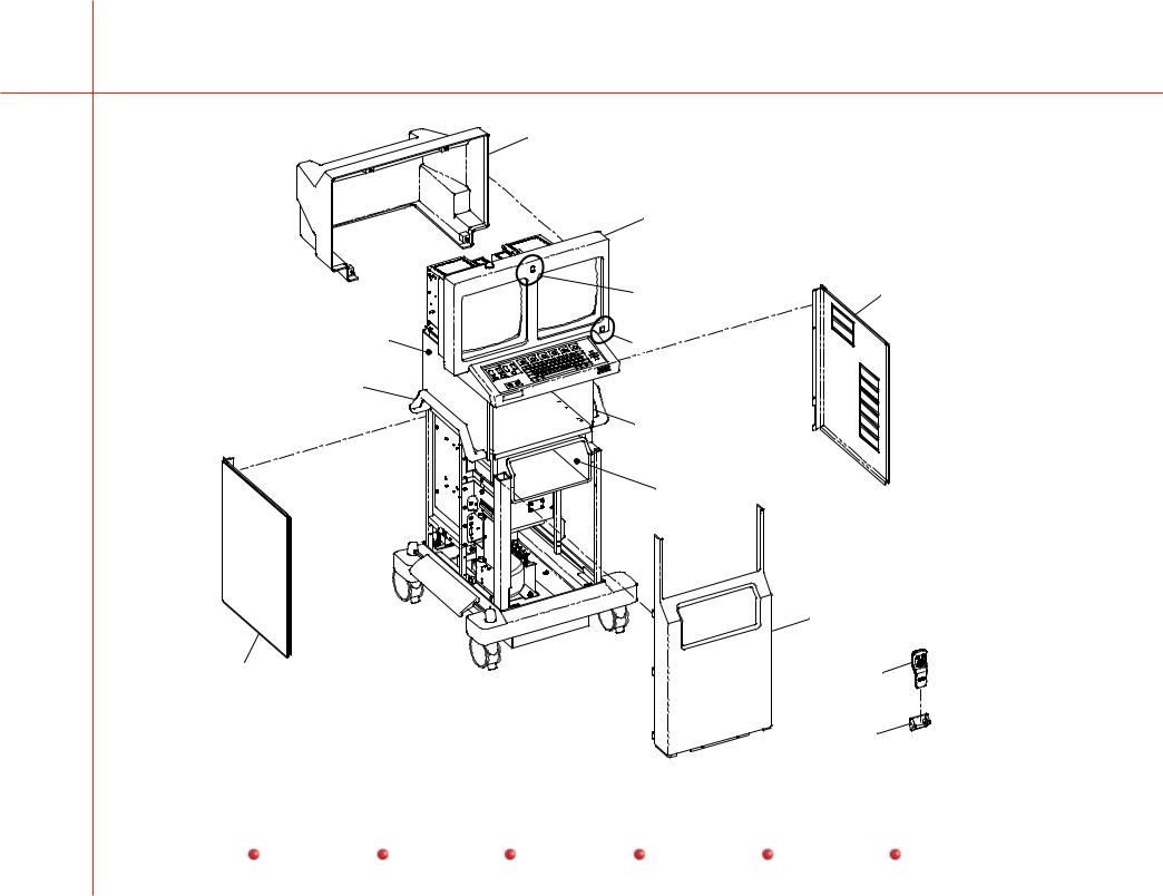
Figure 1. Front, Monitor, and Side Covers Parts List
Item |
Part Number |
Description |
Qty |
1 |
00-875983-02 |
Assembly, Housing, Monitor |
1 |
2 |
00-880616-01 |
Bezel, Monitor |
1 |
3 |
00-880660-01 |
Lens, Front, Colored |
1 |
3 |
00-880660-02 |
Lens, Front, Clear |
1 |
4 |
00-879474-01 |
Assembly, Cable, On/Off, WorkStation |
1 |
5 |
00-875986-07 |
Cover, Side Lower, Right |
1 |
6 |
27-590973-00 |
Filter, Small |
2 |
7 |
27-590974-00 |
Filter, Large |
2 |
8 |
00-875981-04 |
Cover, Side, Upper, Right |
1 |
9 |
00-880829-01 |
Asm, Cover, Shelf, Lower |
1 |
10 |
00-880393-02 |
Cover, Front Panel |
1 |
11 |
00-901382-02 |
Asm, I.R. Remote, 9800 |
1 |
12 |
00-879636-01 |
Holder, Hand Control, 9800 |
1 |
13 |
00-875986-06 |
Cover, Side Lower, Left |
1 |
14 |
00-876466-02 |
Handle, Monitor Cart |
2 |
15 |
00-875981-03 |
Cover, Side, Upper, Left |
1 |
Contents |
Installation |
Service |
Schematics |
Periodic Maintenance |
Illustrated Parts |
OEC Workstation Illustrated Parts Manual |
9 |
1
2
|
3 |
5 |
|
|
6 |
15 |
|
7 |
4 |
|
|
|
|
14
8
9
|
10 |
13 |
11 |
5 |
|
|
12 |
Figure 1. Front, Monitor, and Side Covers Exploded View
Contents |
Installation |
Service |
Schematics |
Periodic Maintenance |
Illustrated Parts |

OEC Workstation Illustrated Parts Manual |
10 |
Figure 2. Rear and Side Covers Parts List
Item |
Part Number |
Description |
Qty |
1 |
00-875986-06 |
Cover, Side Lower |
1 |
2 |
00-879309-01 |
Cover, Rear Panel |
1 |
3 |
23-621841-00 |
Fastener, 1/4 Turn, Stud, Philips, SZC |
6 |
4 |
00-875986-07 |
Cover, Side Lower |
1 |
Contents |
Installation |
Service |
Schematics |
Periodic Maintenance |
Illustrated Parts |
OEC Workstation Illustrated Parts Manual |
11 |
4
1
3
2
Figure 2. Rear and Side Covers Exploded View
Contents |
Installation |
Service |
Schematics |
Periodic Maintenance |
Illustrated Parts |

OEC Workstation Illustrated Parts Manual |
12 |
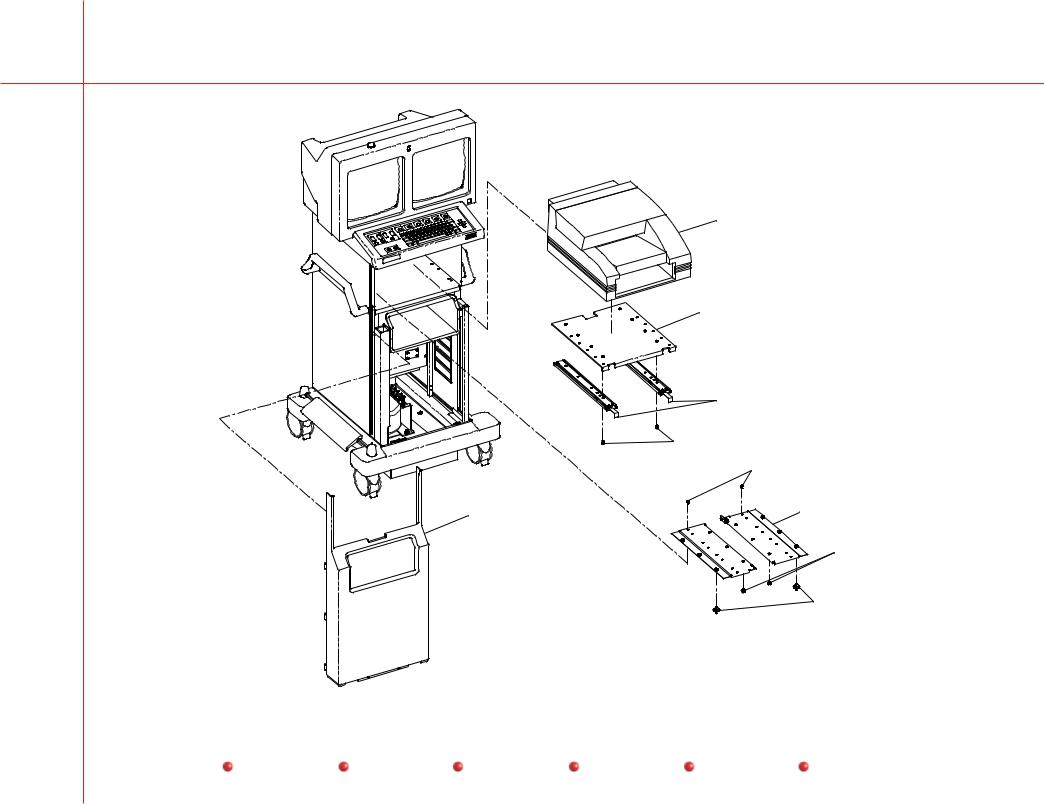
Figure 3. Front Cover with Codonics Printer Parts List
Item |
Part Number |
Description |
Qty |
1 |
00-901406-01 |
Instant Film/Paper Printer |
1 |
2 |
00-880891-01 |
Mount, Upper, Codonics |
1 |
3 |
21-301871-00 |
Rail, Slide, Ball Bearing, Chassis |
2 |
4 |
12-225108-06 |
Screw, SEMS, Spring, Pan, Torx, 8-32, 3/8, SZC |
8 |
5 |
12-225108-06 |
Screw, SEMS, Spring, Pan, Torx, 8-32, 3/8, SZC |
16 |
6 |
00-880892-01 |
Mount, Lower, Codonics |
2 |
7 |
23-608980-00 |
Bumper, Stud Mount, .625D X .312 Thread, Rubber, Black |
6 |
8 |
21-699937-00 |
Mount, Shock Absorber, 60lb, Compression, 15lb sheer |
6 |
9 |
00-880393-04 |
Cover, Front Panel |
1 |
Contents |
Installation |
Service |
Schematics |
Periodic Maintenance |
Illustrated Parts |
OEC Workstation Illustrated Parts Manual |
13 |
1
2
3
4
5
9 |
6 |
|
7
8
Figure 3. Front Cover with Codonics Printer Exploded View
Contents |
Installation |
Service |
Schematics |
Periodic Maintenance |
Illustrated Parts |
Loading...