


LP 33

GE Consumer & Industrial
Power Protection
L
P
S
3
3
U
_
0
3
0
-
0
4
0
_
U
P
S
_
G
E
_
0
1
D
i
g
i
t
a
l
E
n
e
r
g
y
T
M
L
P
S
e
r
ie
s
Operating Manual
Uninterruptible Power supply
Digital Energy™
LP 33 Series
30 & 40 kVA
208 VAC UL / Series 0
Manufactured by:
GE Zenith Controls
General Electric Company
2501 Pecan Street
Bonham, Texas 75418
T 903 640 7900
T 903 640 7900
www.geindustrial.com/cwc/home

Modifications reserved Page 2/57
OPM_LPS_3UO_30K_40K_0US_V010.doc Operating Manual LP 33 Series 30 & 40 kVA
Model: LP 33 Series / 30 & 40 kVA / Series 0
Date of issue: 01/01/2005
File name: OPM_LPS_3UO_30K_40K_0US_V010
Revision: 1.0
Identification No.
Up-dating
Revision Concerns Date
COPYRIGHT © 2005 by GE Consumer & Industrial
All rights reserved.
The information contained in this publication is intended solely for the purposes indicated.
The present publication and any other documentation supplied with the UPS system is not to be
reproduced, either in part or in its entirety, without the prior written consent of GE.
The illustrations and plans describing the equipment are intended as general reference only and are
not necessarily complete in every detail.
The content of this publication may be subject to modification without prior notice.
Modifications reserved Page 3/57
OPM_LPS_3UO_30K_40K_0US_V010.doc Operating Manual LP 33 Series 30 & 40 kVA
Dear Customer,
We thank you for selecting our products and
are pleased to count you amongst our very
valued customers at GE.
We trust that the use of the LP 33 Series
Uninterruptible Power Supply system,
developed and produced to the highes
t
standards of quality, will give you complete
satisfaction.
Please carefully read the Installation Guide.
It contains all the necessary information abou
t
the installation of the UPS.
Thank you for choosing GE !
START UP AND COMMISSIONING
A GE Global Services Field Engineer must perform start-up and commissioning of the
UPS. Please Contact G.E. Global Services at least two weeks prior to schedule start-up
and commissioning at 1-800-637-1738, or by E-mail at gedeservices@indsys.ge.com
Manufactured by:
Distributed by:
Your service contact:
g
GE Digital Energy
General Electric Company
CH – 6595 Riazzino (Locarno)
Switzerland

Modifications reserved Page 4/57
OPM_LPS_3UO_30K_40K_0US_V010.doc Operating Manual LP 33 Series 30 & 40 kVA
Preface
Congratulations on your choice of a LP 33 Series Uninterruptible Power Supply (UPS).
It will help eliminate load disturbances due to unexpected power problem.
This Installation Guide describes how to prepare the installation site, and it provides
weight and dimensions and procedures for moving, installing and connecting the UPS.
While every care has been taken to ensure the completeness and accuracy of this
manual, GE assumes no responsibility or liability for any losses or damages resulting from
the use of the information contained in this document.
WARNING!
LP 33 Series / 30 & 40 kVA, is a product that needs to be installed by a licensed and
knowledgeable contractor.
We recommend that this manual be kept next to the UPS for future references.
If any problems are encountered with the procedures contained in this manual, please
contact your Service Center before you proceed.
This document shall not be copied or reproduced without the permission of GE.
Some of the information contained in this manual may be changed without notice to
reflect technical improvements.
Safety instructions
Read the safety instructions contained on the following pages carefully before the
installation of the UPS, options and battery system.
Pay attention to the rectangular boxes included in the text:
They contain important information and warning concerning electrical connections and
personnel safety.
Parallel version secured with RPA
When included in the text, this symbol refers to operation needed
only for parallel system.

Modifications reserved Page 5/57
OPM_LPS_3UO_30K_40K_0US_V010.doc Operating Manual LP 33 Series 30 & 40 kVA
Table of contents
Page
1
SAFETY RULES.............................................................................................................................................6
2 INTRODUCTION..........................................................................................................................................9
2.1
GENERAL DESCRIPTION......................................................................................................................................................................9
3 DESCRIPTION............................................................................................................................................10
3.1
BLOCK DIAGRAM AND MAIN ELEMENTS DESCRIPTION.................................................................................................... 10
3.2
OPERATION MODES........................................................................................................................................................................... 11
3.3
RPA PARALLEL SYSTEM.................................................................................................................................................................... 14
3.4
UPS PARALLELED ON THE SAME BATTERY.............................................................................................................................. 15
3.5 SERVICE AND TECHNICAL SUPPORT.......................................................................................................................................... 16
3.6
RECYCLING AT THE END OF SERVICE LIFE .............................................................................................................................. 17
4 LAYOUT......................................................................................................................................................18
4.1
LAYOUT LP 33 SERIES / 30 & 40 KVA......................................................................................................................................... 18
5 SYSTEM HANDLING..................................................................................................................................19
5.1
CONTROL PANEL ................................................................................................................................................................................ 19
5.2 COMMAND PUSH BUTTONS AND SWITCHES ........................................................................................................................ 20
6
LCD SCREEN..............................................................................................................................................21
6.1 METERING SCREENS (METERING)................................................................................................................................................ 21
6.2
EVENT SCREENS (ALARM)................................................................................................................................................................ 23
6.2.1
Alarms list.................................................................................................................................................................................................... 23
6.2.2
Messages list.............................................................................................................................................................................................. 26
6.2.3 Event report LP 33 Series...................................................................................................................................................................... 29
6.3
MENU SCREENS (MENU).................................................................................................................................................................. 30
6.3.1 User parameters screen....................................................................................................................................................................... 31
7 OPERATION ...............................................................................................................................................35
7.1
PROCEDURES FOR SINGLE LP 33 SERIES................................................................................................................................. 35
7.1.1
Start-up of the LP 33 Series................................................................................................................................................................. 35
7.1.2
UPS shutdown with load transfer on manual bypass (Q2)................................................................................................... 37
7.1.3 Start-up following the operation on manual bypass (Q2)..................................................................................................... 39
7.1.4
Complete shutdown ............................................................................................................................................................................... 40
7.1.5
Restore to normal operation after “total off”.............................................................................................................................. 41
7.1.6
Restore to normal operation after “EPO – Emergency Power Off”.................................................................................... 42
7.2
PROCEDURES FOR PARALLEL SYSTEM LP 33 SERIES .........................................................................................................43
7.2.1 Parallel System start-up of the LP 33 Series................................................................................................................................43
7.2.2
Parallel UPS shutdown with load transfer on manual bypass (Q2)................................................................................... 45
7.2.3
Start-up following the operation on maintenance bypass (Q2)......................................................................................... 47
7.2.4
Shutdown of a single unit in a parallel system .......................................................................................................................... 48
7.2.5
Start-up an additional unit in a parallel system ........................................................................................................................ 49
7.2.6 Complete shutdown of a parallel system..................................................................................................................................... 50
7.2.7
Restore to normal operation after “total off”.............................................................................................................................. 51
7.2.8
Restore to normal operation after “EPO – Emergency Power Off”.................................................................................... 52
8 OPTIONS....................................................................................................................................................53
8.1
OPTIONS GENERAL VIEW................................................................................................................................................................ 53
9 MAINTENANCE .........................................................................................................................................54
9.1
GENERAL MAINTENANCE................................................................................................................................................................ 54
9.2 COOLING FAN MAINTENANCE...................................................................................................................................................... 54
9.3
BATTERY MAINTENANCE................................................................................................................................................................. 54
9.4 SERVICE REQUIRED ........................................................................................................................................................................... 55
10
NOTES........................................................................................................................................................56
10.1
NOTES FORM........................................................................................................................................................................................ 56
Modifications reserved Page 6/57
OPM_LPS_3UO_30K_40K_0US_V010.doc Operating Manual LP 33 Series 30 & 40 kVA
1 SAFETY RULES
With this document, GE gives to the user all the necessary information about the correct use of the UPS.
We recommend that this manual be kept next to the UPS for future references.
If any problems are encountered with the procedures contained in this manual, please contact the
nearest Service Center before you proceed.
All UPS installation, maintenance and service work should be performed by qualified service personnel
only.
The KNOWLEDGE and the FULLY compliance of the safety instructions and the warning
contained in this manual are
THE ONLY CONDITION
to avoid any dangerous situations during installation, operation, maintenance work, and
to preserve the maximum reliability of the UPS system.
NOTE !
LP 33 Series / 30 & 40 kVA is a FCC Class A-UPS Product.
While every care has been taken to ensure the completeness and accuracy
of this manual, GE assumes no responsibility or liability for any losses or
damages resulting from the use of the information contained in this
document.
GE
Refuses any responsibility in case of non-observance,
unauthorised alterations or improper use of the
delivered UPS.

Modifications reserved Page 7/57
OPM_LPS_3UO_30K_40K_0US_V010.doc Operating Manual LP 33 Series 30 & 40 kVA
SAVE THESE INSTRUCTIONS
This manual contains important instructions for models LP 33 Series / 10 & 20 kVA that should
be followed during installation and maintenance of the UPS and battery.
GENERAL
- Move the UPS in an upright position in its original package to the final destination
room.
- Check for sufficient floor and elevator loading capacity.
- Check the integrity of the UPS equipment carefully.
If you notice visible damage, do not install or start the UPS. Contact the nearest Service
Center immediately.
- WARNING! RISK OF ELECTRICAL SHOCK: Do not remove covers; there are no user
serviceable parts inside.
- After switching off takes 5 minutes for the DC capacitors to discharge because a lethally
high voltage remains at the terminals of the electrolytic capacitors.
- All maintenance and service work should be performed by qualified service personnel.
The UPS contains its own energy source (battery).
- The field-wiring terminals may be electrically live, even when the UPS is disconnected
from the utility.
- Dangerous voltages may be present during battery operation.
The battery must be disconnected during maintenance or service work.
- This UPS contains potentially hazardous voltages.
- Be aware that the inverter can restart automatically after the utility voltage is restored.
STORAGE
- Store the UPS in a dry location; storage temperature must be within -13°F (-25°C) to
131°F (55°C).
- If the unit is stored for a period exceeding 3 months, the battery must be recharged
periodically (time depending on storage temperature).
BATTERY
- The battery-voltage is dangerous for person’s safety.
- When replacing the battery, use the same number, voltage (V) and capacity (Ah).
- Proper disposal or recycling of the battery is required.
Refer to your local codes for disposal requirements.
- Never dispose of battery in a fire: They may explode.
- Do not open or mutilate battery: Their contents (electrolyte) may be extremely toxic.
If exposed to electrolyte, wash immediately with plenty of water.
- Avoid charging in a sealed container.
- Never short circuit battery. When working with battery, remove watches, rings or other
metal objects, and only use insulated tools.
Modifications reserved Page 8/57
OPM_LPS_3UO_30K_40K_0US_V010.doc Operating Manual LP 33 Series 30 & 40 kVA
Safety symbols and warnings
Safety warnings
The text of this manual contains some warnings to avoid risk to the persons and to avoid damages to
the UPS system and the supplied critical loads.
The non-observance of the warnings reminding hazardous situations could result in human injury and
equipment damages.
Please pay attention to the meaning of the following warnings and symbols.
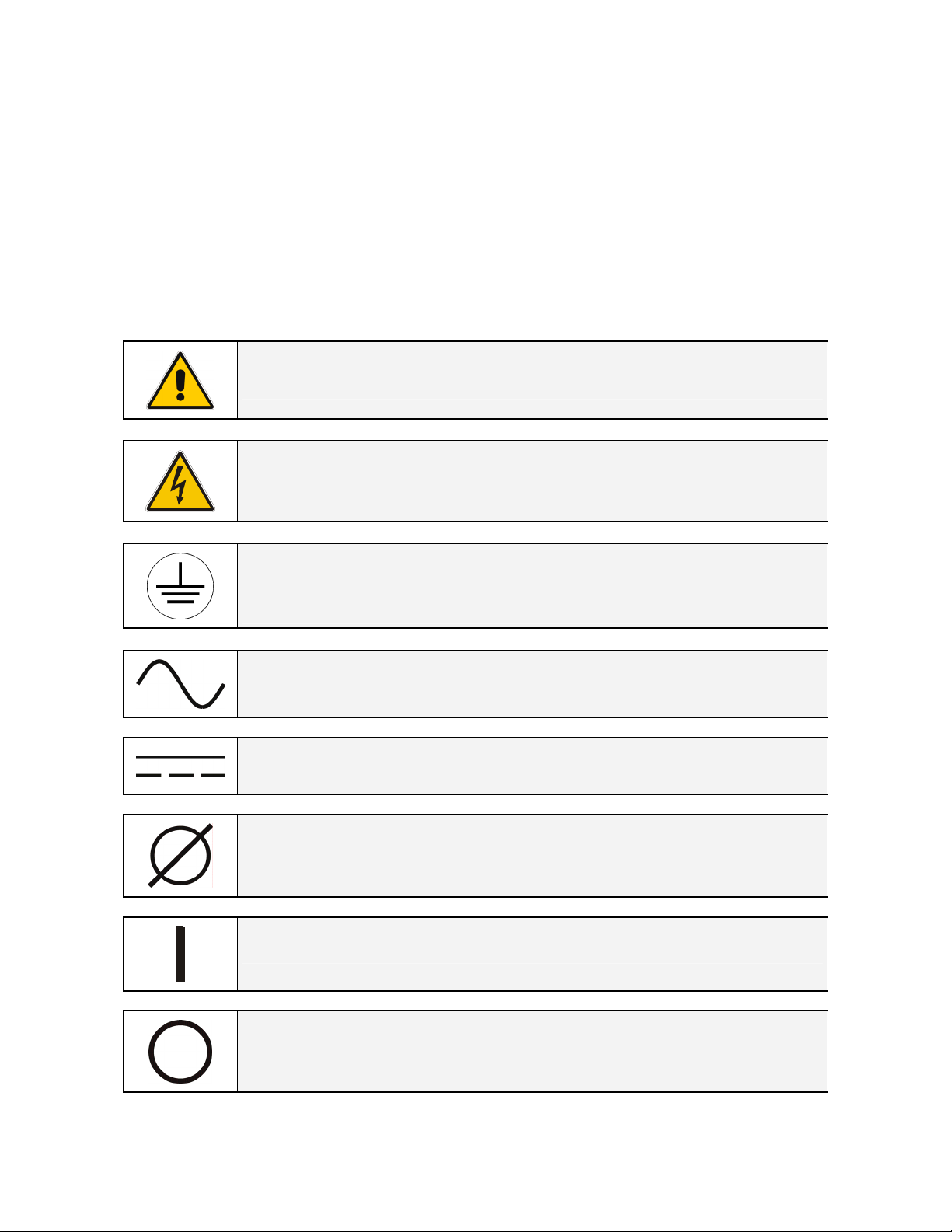
Throughout this manual the following symbols are defined:
WARNING, if instruction is not followed injury or serious equipment damage
may occur!
CAUTION, internal parts have dangerous voltage present.
Risk of electric shock!
PE (Earth) – GND (Ground)
PROTECTIVE GROUNDING TERMINAL:
A terminal which must be connected to earth ground prior to making any other
connection to the equipment.
A terminal to which or from which an alternating (sine wave) current or voltage
may be applied or supplied.
A terminal to which or from which a direct current or voltage may be applied or
supplied.
This symbol indicated the word “phase”.
This symbol indicates the principal on/off switch in the on position.
This symbol indicates the principal on/off switch in the off position.
Modifications reserved Page 9/57
OPM_LPS_3UO_30K_40K_0US_V010.doc Operating Manual LP 33 Series 30 & 40 kVA
2 INTRODUCTION
2.1 GENERAL DESCRIPTION
The LP 33 Series Uninterruptible Power Supply (UPS) provides the energy supply for critical loads which
need a reliable, continuous free from voltage disturbances and frequency fluctuations supply.
In case the mains fails, or it exceeds the permitted tolerances, the energy to supply the load is furnished
by the battery with a backup time dependent on its capacity, until the mains recovers.
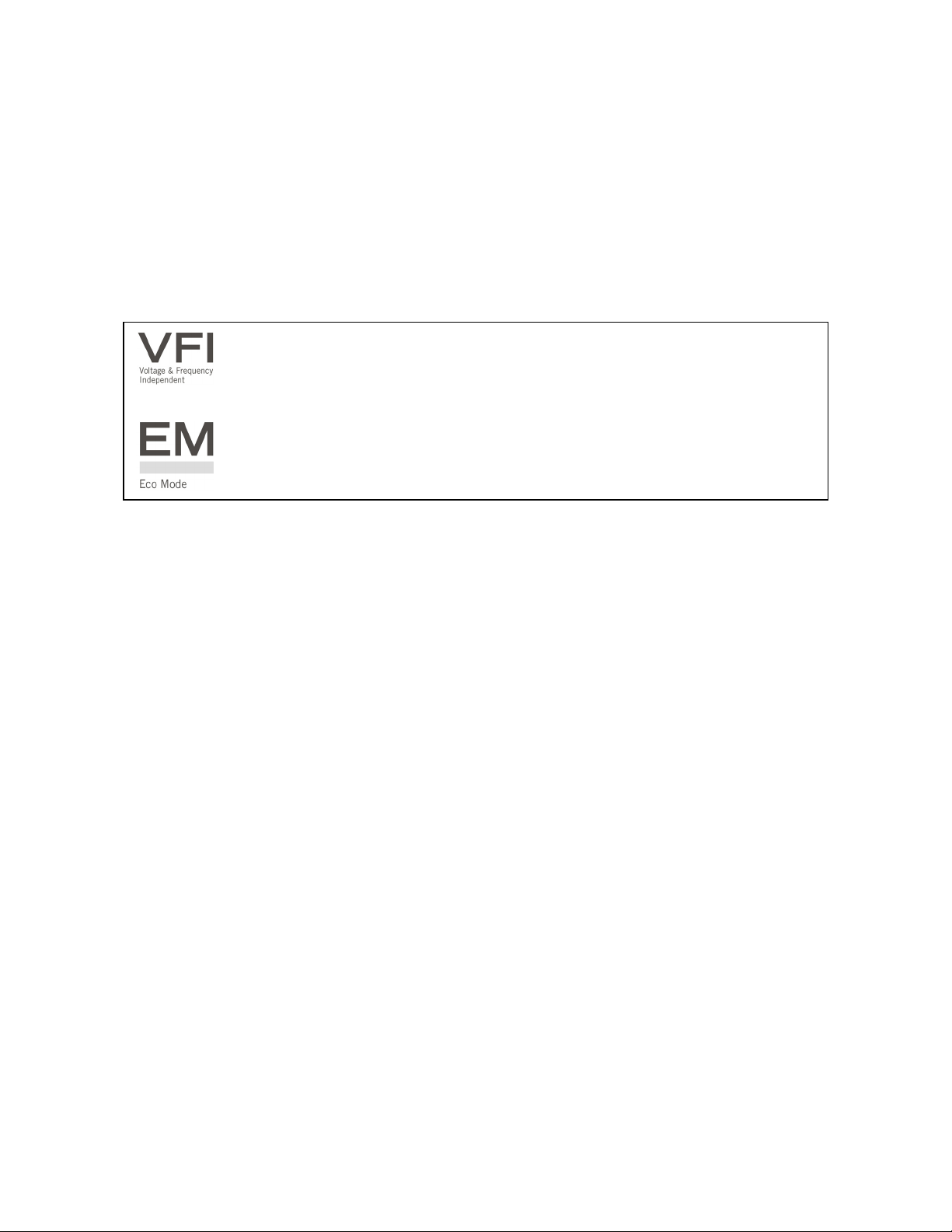
LP 33 Series is a truly VFI double conversion Uninterruptible Power Supply (UPS),
equipped with automatic bypass, where the load is normally supplied by the inverter.
LP 33 Series can be configured, if chosen, for the ECO Mode permitting the maximum
energy saving.
The main typical performances of the LP 33 Series system are the following:
•
VFI (Voltage Frequency Independent) double conversion technology to provide an excellent
quality power supply.
•
Input power factor 0.8.
• Input current THD <10%.
• Automatic bypass and manual bypass to improve reliability and maintenance.
•
Microprocessor controlled supervision.
• Dual AC inputs (optional).
• ECO Mode operation.
• Compact and agreeable design expressly conceived for “Office environment”.
• Low level acoustic sound, 50 dB(A) (10 kVA), 55 dB(A) (20 kVA) and 61 dB (A) (30 & 40 kVA) to avoid
noise to the persons operating in the same environment.
• Multi-language LCD screen.
•
Total battery management: SBM (Superior Battery Management)
• High battery capacity, 22 minutes (10 kVA), 9 minutes (20 kVA), 29 minutes (30 kVA) and 19
minutes (40 kVA), with battery housed in the UPS cabinet.
• Wide rectifier input voltage tolerance: 152 ÷ 240 VAC (phase – phase).
• Wide rectifier input frequency tolerance: +/-10% (54 ÷ 66 for 60 Hz).
•
RPA (Redundant Parallel Architecture) up to 4 units.
• GE Connectivity.
• Compliance with UL standard 1778.

Modifications reserved Page 10/57
OPM_LPS_3UO_30K_40K_0US_V010.doc Operating Manual LP 33 Series 30 & 40 kVA
3 DESCRIPTION
3.1 BLOCK DIAGRAM AND MAIN ELEMENTS DESCRIPTION
Fig. 3.1-1 UPS block diagram
The Uninterruptible Power Supply System LP 33 Series / 30 & 40 kVA can be divided into the following
main elements:
Electronics
The UPS is designed with a microprocessor–controlled supervision and diagnostic system.
Communication between user and UPS is achieved by the front panel consisting of an LCD screen,
displaying the operation modes, the measurements and the events / alarms.
Rectifier
The rectifier converts the 3-phase mains voltage into a controlled and regulated DC-voltage, in order to
supply power to the booster, and to charge the battery through the battery-charger.
Inverter
The inverter converts the DC voltage into a three-phase AC-voltage with constant amplitude and
frequency, which is completely independent from the AC-input voltage.
Automatic Bypass
The automatic bypass consists of a static semiconductor-switch (SSR: Static Switch Relay), used to
provide an uninterrupted transfer of the load from inverter to mains when operating in VFI Mode.
If chosen the ECO Mode, the SSM transfer the load from mains to inverter in case the utility fails.
Back-Feed Protection
All LP 33 Series UPS’s are equipped with an automatic system for the protection against voltage back
feeding towards Utility, through the Bypass (Applied Standard IEC 62040-1).
This protection works automatically by opening contactor K6 (in series with the thyristors of the static
switch) and eventually K7, and acts in case of internal defects of the system, or due to wrong
manipulations on the maintenance bypass Q2.
Manual Bypass
The manual bypass consists of a pair of manual switches Q1 and Q2, which allow the isolation of the
UPS from the load, while still supplying the load with power directly from the mains.
Battery
The battery, normally stored by the battery-charger, supplies the DC energy to inverter in the event of
mains failure.
Modifications reserved Page 11/57
OPM_LPS_3UO_30K_40K_0US_V010.doc Operating Manual LP 33 Series 30 & 40 kVA
3.2 OPERATION MODES
This section describes the different possible operation modes of the UPS explaining the function of the
main modules of the UPS.
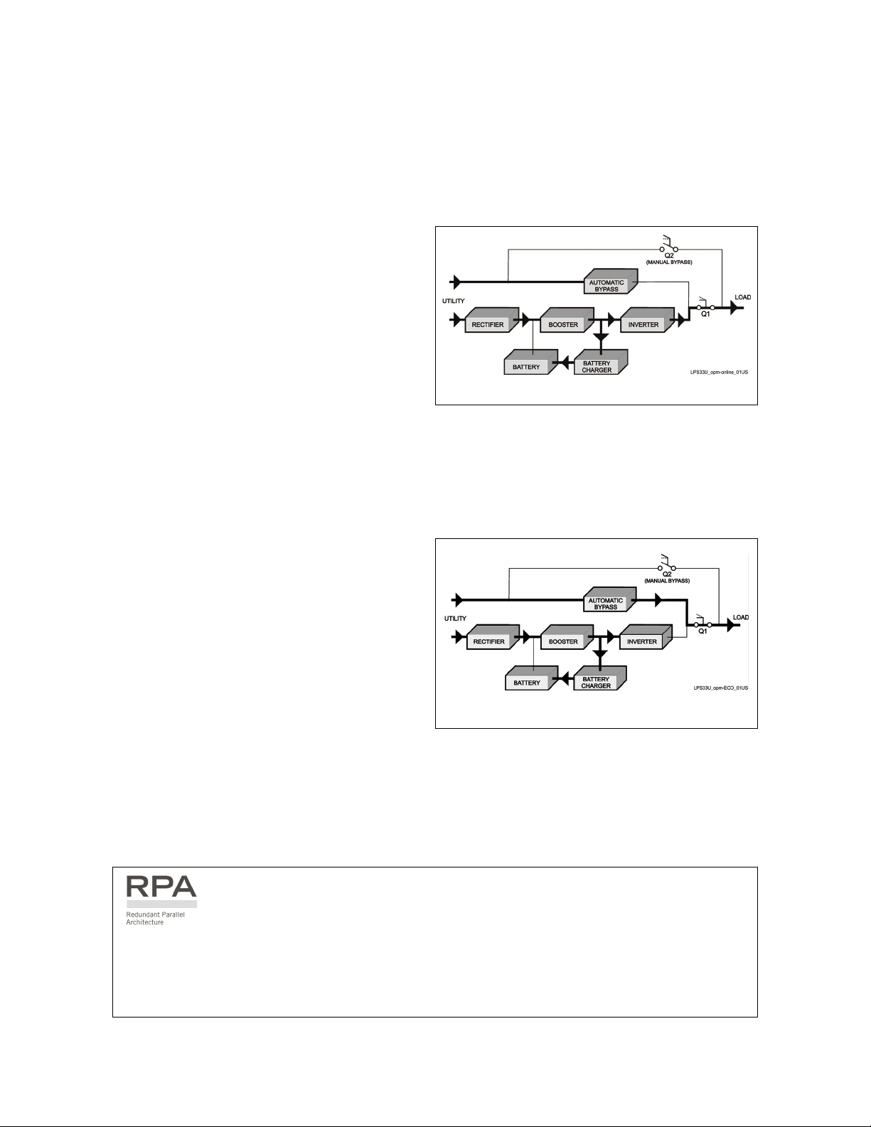
VFI (Voltage Frequency Independent) Mode operation
Under normal conditions the load is
permanently powered by the inverter with
constant amplitude and frequency.
The rectifier, powered by the mains, supplies the
inverter and the battery-charger keeps the
battery fully charged.
Fig. 3.2-1 Energy flow in VFI Mode operation
The inverter converts the DC voltage in a new AC sine wave voltage with constant amplitude and
frequency independently from the input mains power.
ECO Mode operation (Intelligent Energy Management)
When the ECO Mode is selected, and the mains
power is available, the load is normally powered
through the automatic bypass.
When the mains voltage is detected out of the
prescribed tolerances, the load is automatically
transferred to the inverter.
When the mains recovers, the load returns to
the automatic bypass after a variable time
defined by the control unit.
Fig. 3.2-2 Energy flow in ECO Mode operation
The ECO Mode can be configured directly by the user for higher efficiency, considering the mains
reliability and criticality of the load.
The selection between the two operation modes “VFI Mode and ECO Mode”, or switching between
operation modes at required time, can be done through the UPS control panel (see Section 6.3.1-5).
In case of parallel system
ECO Mode cannot be enabled for RPA Parallel System.
Attention: A single unit equipped with a RPA - Parallel board, must be considered as parallel, thus
disabling ECO Mode.
Modifications reserved Page 12/57
OPM_LPS_3UO_30K_40K_0US_V010.doc Operating Manual LP 33 Series 30 & 40 kVA
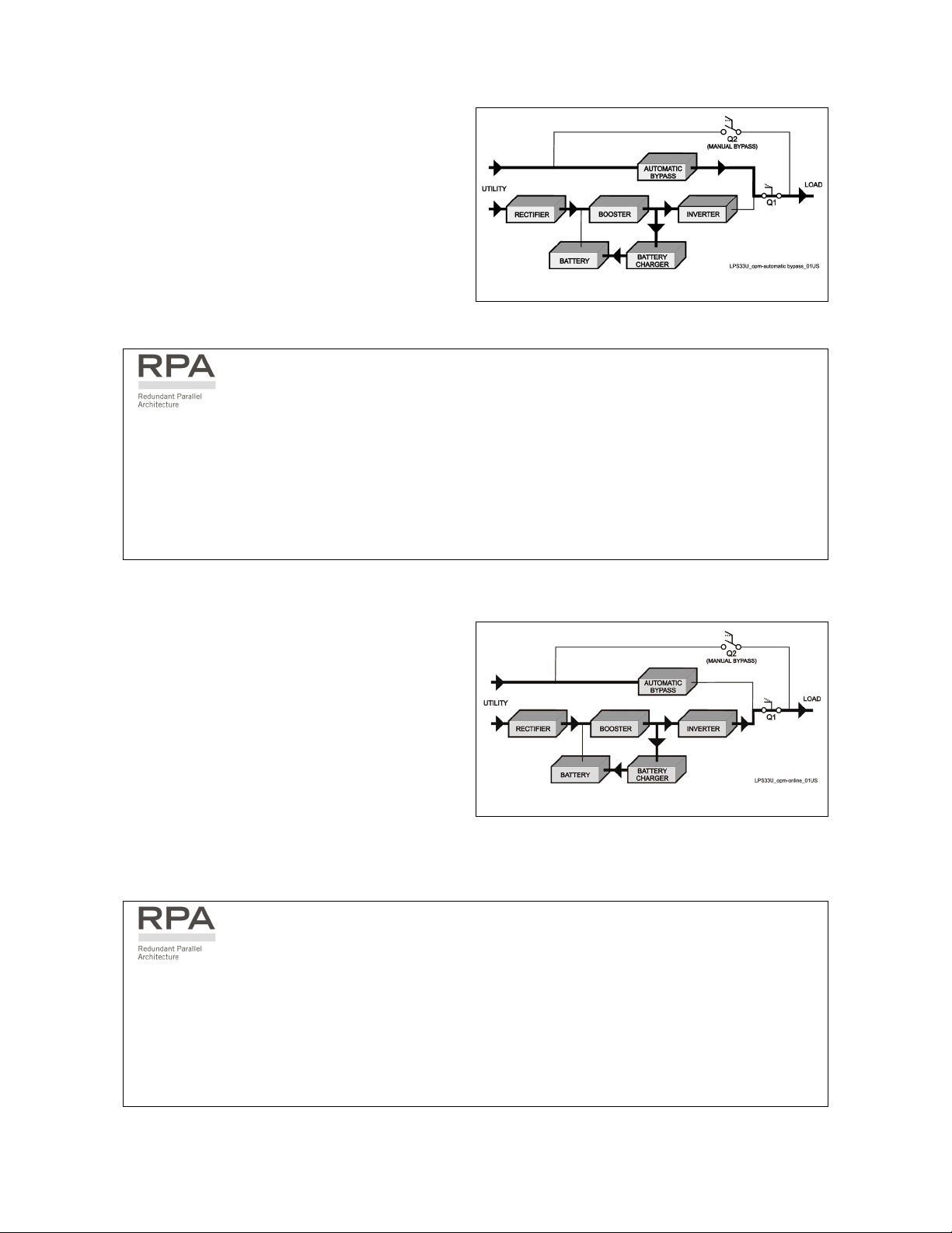
Automatic bypass operation
In VFI (Voltage Frequency Independent) operation
mode, the load is permanently supplied by the
inverter but, in case of trouble on the inverter, or
when overload or short-circuit on the output
occur, if the mains voltage do not exceed the
admitted tolerances, the load is instantly
transferred to the mains through the automatic
bypass, taking advantage of the higher short
circuit power.
Fig. 3.2-3 Energy flow in automatic bypass operation
When the inverter recovers, the load will be re-transferred automatically to the inverter.
In case of parallel system
Each unit has its own bypass.
All the bypasses in the system work together, their control being managed in the same manner by
all units.
The units are continuously exchanging information before taking such decision.
In case the inverter of one unit fails, its bypass remains operating.
It is excluded only if the unit is separated from the common bus by opening its output switch Q1.
Mains recovery operation
As soon as the mains recovers, the rectifier starts
up automatically supplying the inverter and the
battery-charger recharges the battery.
In case the inverter has been shut down following
a complete discharge of the battery, when the
mains recovers the system start up automatically.
Fig. 3.2-4 Energy flow at mains recovery operation
When the energy stored in the battery is sufficient to ensure a minimum time of operation with the
actual load, in case of a future mains failure, the load will be retransferred to inverter (if selected VFI
Mode).
In case of parallel system
When the AC input power recovers, the rectifiers will start up sequentially according to their
number in the parallel system in order to avoid an initial inrush current.
The inverters will start up automatically, but only when the battery has recharged enough for a
minimum runtime with the present load.
When enough inverters to supply the load have been restarted, the load will be transferred from the
automatic bypass back to the inverter bus-bars.
Modifications reserved Page 13/57
OPM_LPS_3UO_30K_40K_0US_V010.doc Operating Manual LP 33 Series 30 & 40 kVA
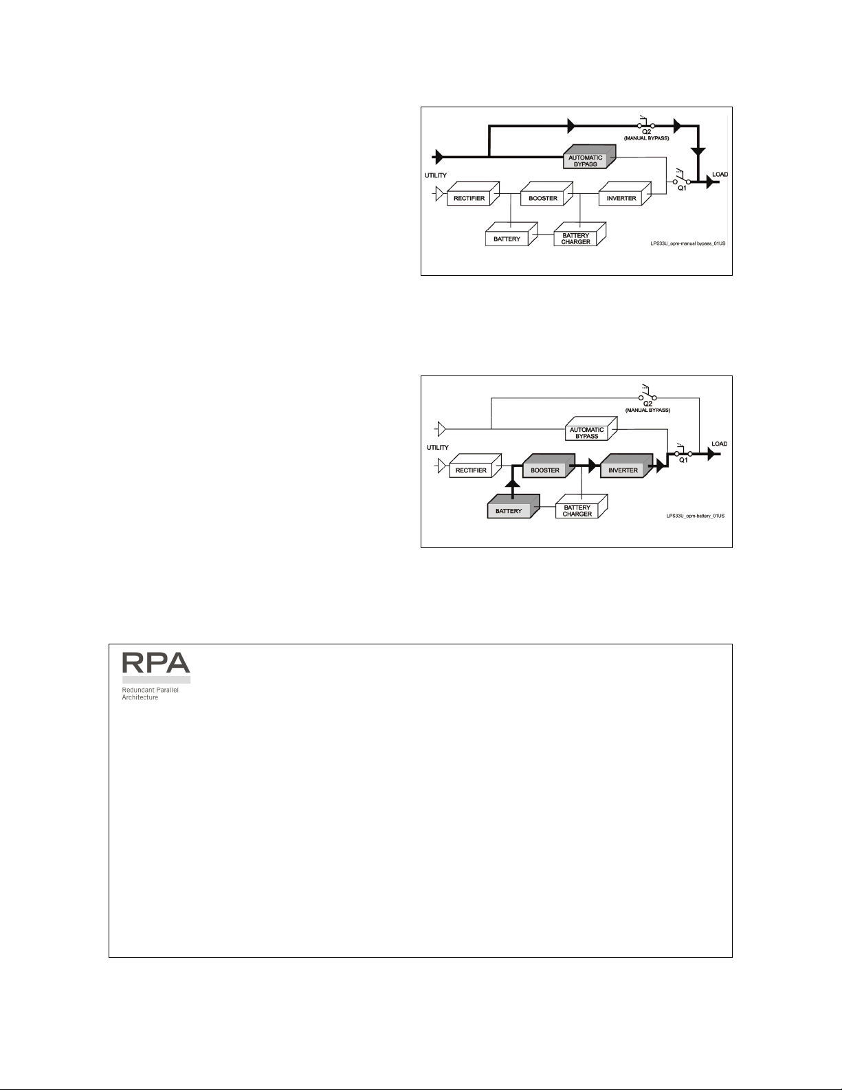
Manual bypass operation
The manual bypass circuit consisting of Q1 and
Q2 manual switches, permits the transfer of the
load directly to the mains without interruption,
leaving the UPS galvanically separated from the
output load.
This type of operation is normally used when the
UPS system must be completely turned off for
maintenance or reparation.
Fig. 3.2-5 Energy flow in manual bypass operation
Mains failure operation
In the event of a mains power failure, the
rectifier and the battery-charger turn OFF,
while the inverter continues to supply the load
without interruption using the energy stored in
the battery.
During the battery discharge, the LCD screen
displays the remaining autonomy, based on the
battery capacity and the applied load.
Fig. 3.2-6 Energy flow during mains failure operation
In the event of an extended mains failure, before the battery is fully discharged, the alarm “stop
operation” warns the user that the UPS will start the shutdown procedures when the indicated time
expired (normally 3 minutes).
In case of parallel system
With parallel system for power capacity:
• With the bypass mains power available as the warning “battery low” occurs on one unit, after
timeout (selectable) the load is transferred to mains.
• With missing bypass mains power as the warning occurs on one unit, the system starts the
timeout (selectable) of “Stop operation” and then the output load shuts down.
With redundant parallel system:
• As the warning battery low occurs on one unit unnecessary to support the present load, after
timeout (selectable) this unit shuts down and the load is shared between the other units.
As the warning occurs on one unit necessary to support the present load, the system starts the
timeout (selectable) of “stop operation” and then the output load shuts down.
Modifications reserved Page 14/57
OPM_LPS_3UO_30K_40K_0US_V010.doc Operating Manual LP 33 Series 30 & 40 kVA
3.3 RPA PARALLEL SYSTEM
The RPA (Redundant Parallel Architecture) allows to extend the unit to a parallel system with 2, 3, or 4
units LP 33 Series connected on the same bus, which ensure the highest reliability rate and increase the
power availability.
Parallel system for power capacity
Two or more units can be paralleled in order to
achieve output power superior to the maximum
power delivered by a single UPS unit.
The maximum total load shared between the n
parallel units can achieve the 100% of the
installed nominal power system.
In the event of one unit fails, the load will be
suddenly transferred to the mains by the
bypass.
Parallel system for redundancy
The parallel system can be defined redundant
only in case the nominal power rating of n-1 units
of n parallel units is sufficient to supply the
required load power.
LPS33U_030-040_RPA system_GE_01
LP 33 Series
1
RPA
Board
LP 33 Series
2
RPA
Board
LP 33 Series
3
RPA
Board
LP 33 Series
4
RPA
Board
F2F1 F3 F4
UTILITY INPU
T
LOA
D
Fig. 3.3-1 RPA system diagram
The load in a parallel redundant system, is equally shared by n units connected on the output bars.
Should one of the parallel units trip off-line, the remaining (n-1) units will share the load maintaining the
applications protected by inverter until the normal situation restores.
Load sharing between parallel units
The control bus exchanging the data between the microprocessors of the paralleled units provide for a
constant proportional load sharing in every load condition.
Management and synchronization of the parallel system
All the units are identical without master and slaves.
One unit is arbitrarily selected as the reference (the first unit connected on power bus) being this unit the
first synchronized with the mains voltage, and all the other units synchronize with the first one.
In case the reference unit fails or it is excluded from the parallel power bus any other unit will take over
the reference role.
The AC input power source of all the bypasses must be the same for all the units of the parallel system
excluding any phase shift between them.
Control bus of the parallel system
A high-speed serial bus, guarantees communication, synchronization and load sharing between the
UPS modules.
Each module controls it’s own function, while the Master (each unit can be Master) controls and
commands the status of the system.
NOTE !
The parallel system exclude more rectifiers connected on common battery.
No transformers, fuses or automatic circuit breakers should be inserted between the
unit’s output and the load common bus bars.
Modifications reserved Page 15/57
OPM_LPS_3UO_30K_40K_0US_V010.doc Operating Manual LP 33 Series 30 & 40 kVA
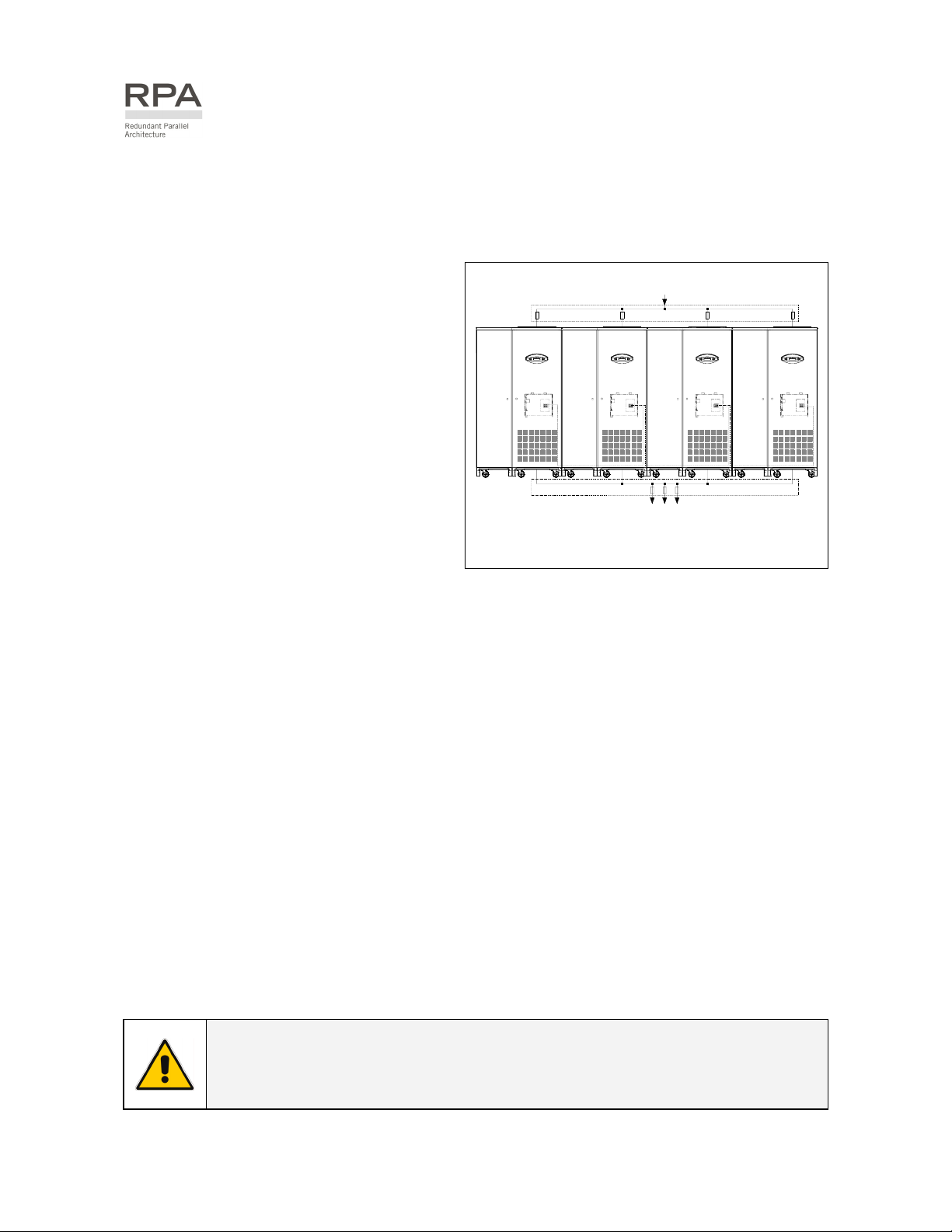
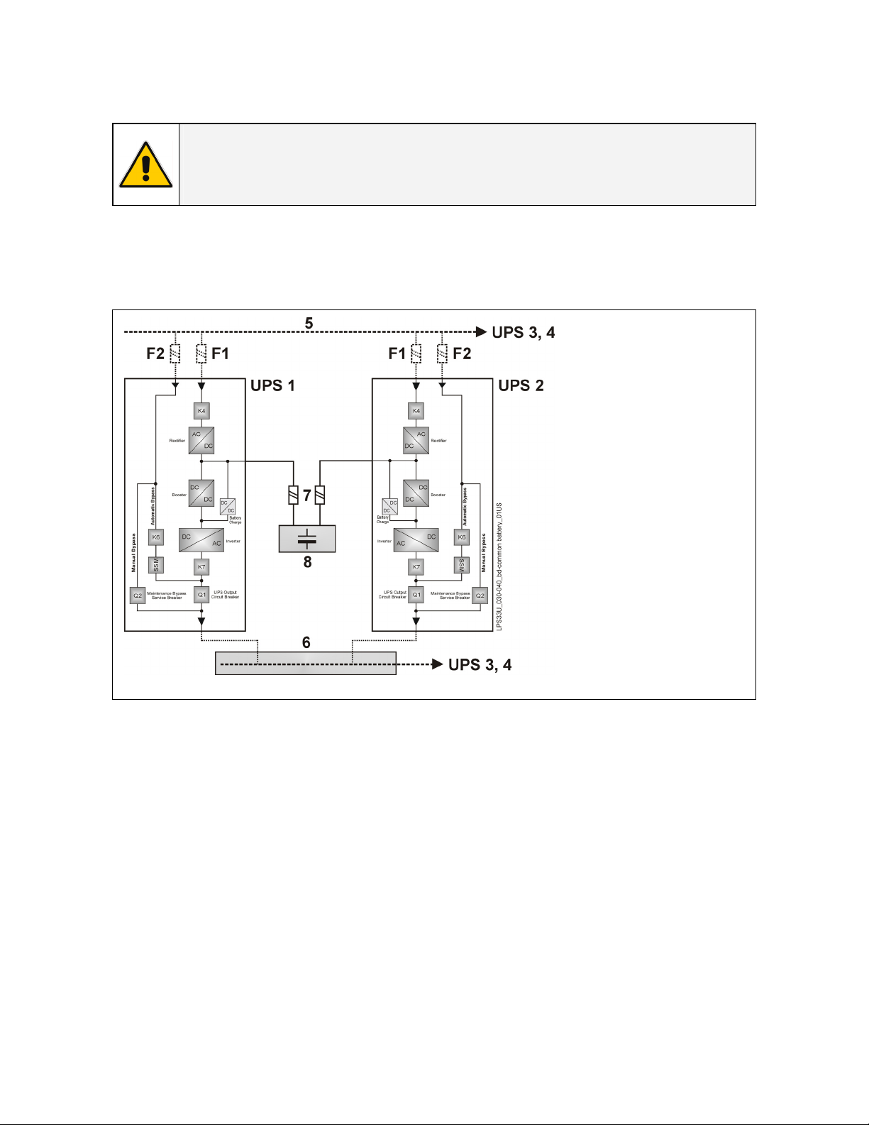
3.4 UPS PARALLELED ON THE SAME BATTERY
NOTE !
A parallel system with a Common Battery for two or more UPS, requires a particular
installation and adequate setting of some parameters, (accessible only through
password), and can therefore only be done by a qualified GE engineer.
Usually each UPS Unit runs with its own Battery.
In case of parallel units running with a Common Battery (max. 4 UPS - see Fig. 3.4-1), the sharing circuit
between the individual UPS is integrated in the communication bus of the system in order to assure an
equal sharing of the Rectifiers output currents.
Fig. 3.4-1 Diagram RPA system with UPS on common battery
1 –
2 –
3 –
4 –
5 –
6 –
7 –
8 –
Rectifier
Inverter
Automatic Bypass
Manual Bypass
Mains Power
Load Bus Bar
External Battery Fuse
Battery
Pay attention to the following recommendations:
•
The units delivered for this functioning mode needs a special parameters setting, so they must be
prepared in advance before the installation.
• The installation must be performed only with the UPS system completely shut down.
• The AC Rectifiers input power (5) must be the same, with clockwise phase rotation for each unit.
•
Each Rectifier must be set for the same floating DC voltage and the same Battery current limitation.
• It is mandatory to install the fuses / MCB (7) on each line connecting the Rectifiers to the common
Battery for maintenance / safety reasons (see Section 4.7.2).
• In case a unit must be powered down for maintenance, switch-OFF the concerned unit before open
the DC fuses / MCB on the Battery line (7).
• If an emergency generator set supplies the UPS, and the free contact “Generator ON” is connected
to the Customer Interface, connect a separate NO free contact on each parallel unit.
• Do not connect the temperature sensor for automatic battery floating voltage compensation.
•
Do not enable the function Boost charge.
Modifications reserved Page 16/57
OPM_LPS_3UO_30K_40K_0US_V010.doc Operating Manual LP 33 Series 30 & 40 kVA
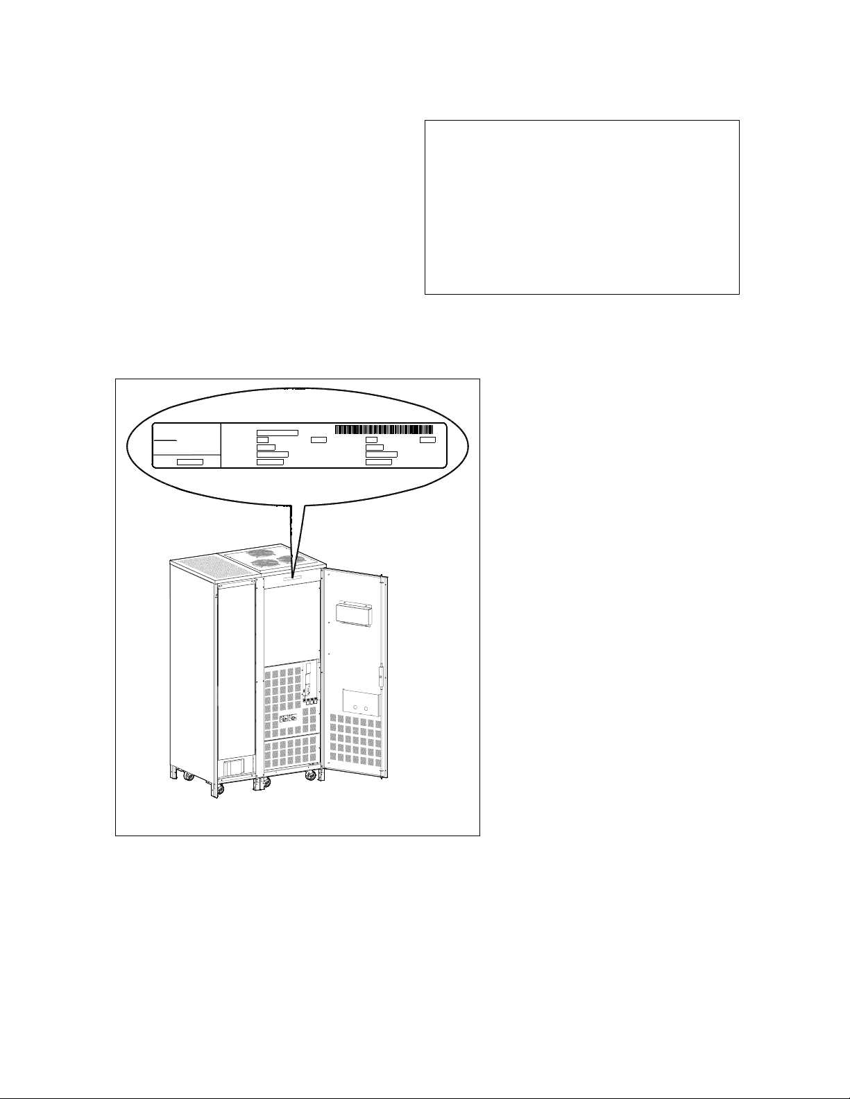
3.5 SERVICE AND TECHNICAL SUPPORT
For any request of technical support please
contact the supplier who provided the system.
Stamp of your Dealer or local responsible of the Technical Assistance
(see page 3)
L
P
S
3
3
U
_
0
3
0
-
0
4
0
_
L
a
b
e
l
i
d
e
n
t
i
f
i
c
a
t
i
o
n
_
G
E
_
0
1
OFF
ON
OFF
ON
kVAOutput Power at Pow. factor
Output Freq. Hz
Output Voltage VAC: 3W + N + PE
Output Current A
lag.Series Product. Year
Input Freq. Hz
Input Voltage VAC: 3W + N + PE
Input Current A
Serial Nr.
Model
g
GE Digital Energy
6595 RIAZZINO (CH)
MADE IN SWITZERLAND
Fig. 3.5-1 Identification label
The requested data permitting to
identify your UPS are marked on the
identification label fixed on the front of
the cabinet, behind the lower front
door.
For fast and efficient Technical Support
solutions, please mention the data
marked on the identification label.
Modifications reserved Page 17/57
OPM_LPS_3UO_30K_40K_0US_V010.doc Operating Manual LP 33 Series 30 & 40 kVA
3.6 RECYCLING AT THE END OF SERVICE LIFE
NOTE !
This product has been designed to respect the environment, using materials
and components respecting eco-design rules.
It does not contain CFCs (Carbon Fluor Clorid) or HCFCs (Halogen Carbon
Fluor Clorid).
GE, in compliance with environment protection recommends to the
User that the UPS equipment, at the end of its service life, must be
recovered conforming to the local applicable regulations.
WARNING !
Leads contained in the batteries is a dangerous substance for the
environment, therefore it must be correctly recycled by specialised
companies!
Modifications reserved Page 18/57
OPM_LPS_3UO_30K_40K_0US_V010.doc Operating Manual LP 33 Series 30 & 40 kVA
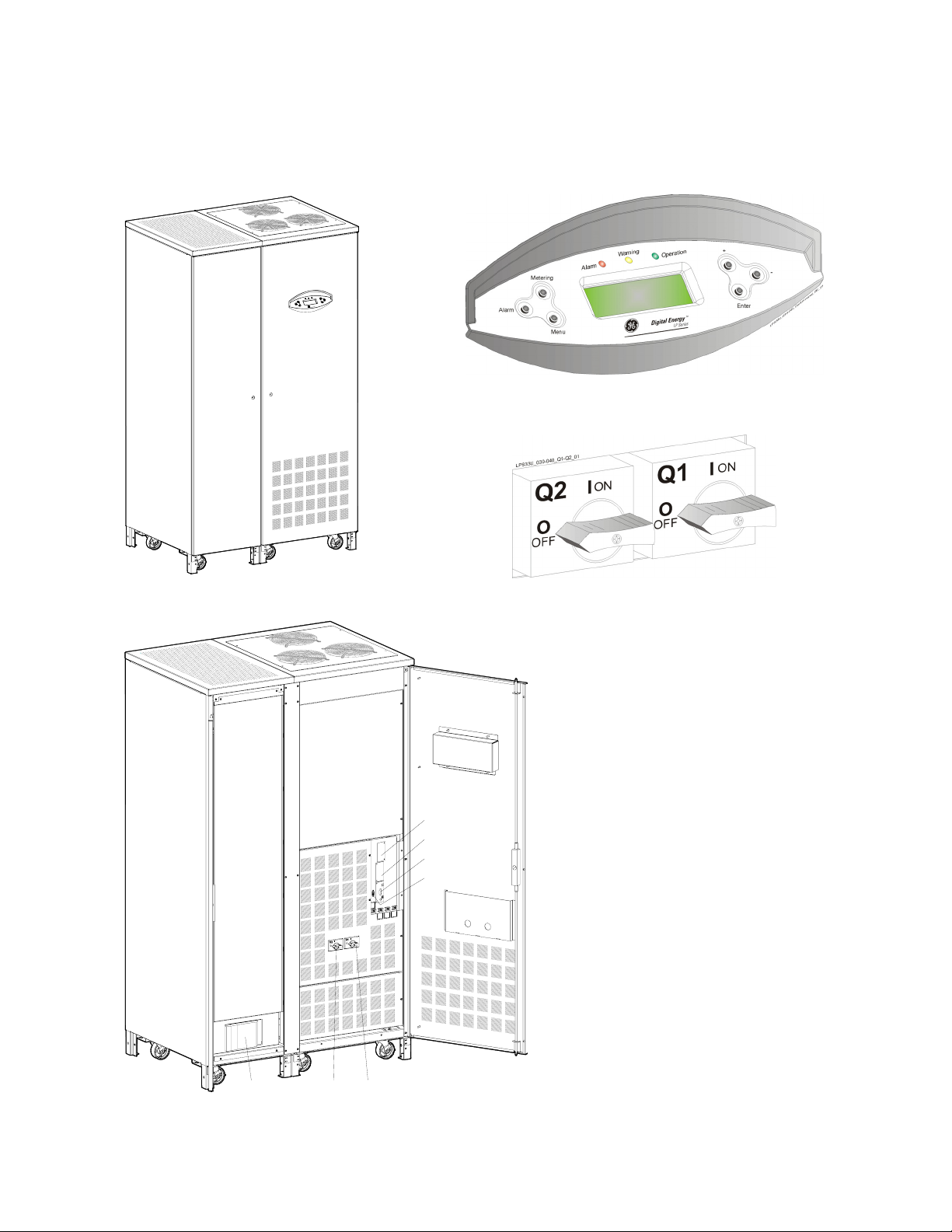
4 LAYOUT
4.1 LAYOUT LP 33 Series / 30 & 40 kVA
Fig. 4.1-3 Control panel
L
P
S
3
3
U
_
0
3
0
-
0
4
0
_
U
P
S
_
G
E
_
0
1
D
i
g
i
t
a
l
E
n
e
r
g
y
T
M
L
P
S
e
r
i
e
s
Fig. 4.1-1 General view
Fig. 4.1-4 Q1 & Q2 switches
BC Battery cabinet
CI Customer Interface Board (optional)
F5-6-7 Battery fuses
Q1 UPS output switch
Q2 Manual bypass switch
RC Relay card
SNMP Advanced SNMP Card (optional)
L
P
S
3
3
U
_
0
3
0
-
0
4
0
_
U
P
S
_
0
4
OFF
ON
OFF
ON
SNMP
CI
RC
F5-6-7
BC
Q2 Q1
RS232
Fig. 4.1-2 General view with open door
RS232 Serial port RS232
 Loading...