


 Loading...
GE Healthcare
MAC™ 800
Resting ECG Analysis System
Software Version 1
Service Manual
2031504-159 Revision B

© 2008 General Electric Company. All rights reserved.
CardioSoft, CASE, Hookup Advisor, MAC, Mactrode, MUSE, and 12SL are trademarks owned by GE Medical Systems Information Technologies, a division of General Electric Company going to market as GE Healthcare.
All other marks are not owned by GE and are instead owned by their respective owners.
NOTE
This manual applies to the MAC™ 800 software version 1. Due to continuing product innovation, specifications in this manual are subject to change without notice.
T-2 |
MAC™ 800 |
2031504-159B |
|
|
15 August 2008 |

Contents
1 Introduction
Manual Information. . . . . . . . . . . . . . . . . . . . . . . . . . . . . . . . . . . . . . . . . . . . . . . . . . . 1-2
Revision History . . . . . . . . . . . . . . . . . . . . . . . . . . . . . . . . . . . . . . . . . . . . . . . . . . . 1-2
Manual Purpose . . . . . . . . . . . . . . . . . . . . . . . . . . . . . . . . . . . . . . . . . . . . . . . . . . . 1-2
Intended Audience . . . . . . . . . . . . . . . . . . . . . . . . . . . . . . . . . . . . . . . . . . . . . . . . . 1-2
Warnings, Cautions, and Notes . . . . . . . . . . . . . . . . . . . . . . . . . . . . . . . . . . . . . . . 1-2
Equipment Information . . . . . . . . . . . . . . . . . . . . . . . . . . . . . . . . . . . . . . . . . . . . . . . 1-3
Safety Messages . . . . . . . . . . . . . . . . . . . . . . . . . . . . . . . . . . . . . . . . . . . . . . . . . . 1-3
Responsibility of the Manufacturer . . . . . . . . . . . . . . . . . . . . . . . . . . . . . . . . . . . . . 1-4
Equipment Symbols . . . . . . . . . . . . . . . . . . . . . . . . . . . . . . . . . . . . . . . . . . . . . . . . 1-4
Product Label Format . . . . . . . . . . . . . . . . . . . . . . . . . . . . . . . . . . . . . . . . . . . 1-5
Serial Number Format. . . . . . . . . . . . . . . . . . . . . . . . . . . . . . . . . . . . . . . . . . . 1-5
Service Requirements . . . . . . . . . . . . . . . . . . . . . . . . . . . . . . . . . . . . . . . . . . . . . . 1-6
2 |
Equipment Overview |
|
|
General Description . . . . . . . . . . . . . . . . . . . . . . . . . . . . . . . . . . . . . . . . . . . . . . . . . . |
2-2 |
|
Front View . . . . . . . . . . . . . . . . . . . . . . . . . . . . . . . . . . . . . . . . . . . . . . . . . . . . . . |
. 2-2 |
|
Side View . . . . . . . . . . . . . . . . . . . . . . . . . . . . . . . . . . . . . . . . . . . . . . . . . . . . . . . |
. 2-3 |
|
Back View . . . . . . . . . . . . . . . . . . . . . . . . . . . . . . . . . . . . . . . . . . . . . . . . . . . . . . |
. 2-3 |
|
Keypad . . . . . . . . . . . . . . . . . . . . . . . . . . . . . . . . . . . . . . . . . . . . . . . . . . . . . . . . . |
. 2-4 |
|
Detailed Description . . . . . . . . . . . . . . . . . . . . . . . . . . . . . . . . . . . . . . . . . . . . . . . . . . |
2-6 |
|
Block Diagram . . . . . . . . . . . . . . . . . . . . . . . . . . . . . . . . . . . . . . . . . . . . . . . . . . . |
. 2-6 |
|
Overview . . . . . . . . . . . . . . . . . . . . . . . . . . . . . . . . . . . . . . . . . . . . . . . . . . . . |
. 2-7 |
|
Hardware/firmware Architecture . . . . . . . . . . . . . . . . . . . . . . . . . . . . . . . . . . |
. 2-8 |
|
Product Interfaces. . . . . . . . . . . . . . . . . . . . . . . . . . . . . . . . . . . . . . . . . . . . . |
. 2-8 |
|
Layered Structure of application software. . . . . . . . . . . . . . . . . . . . . . . . . . . |
. 2-9 |
|
ECG Data Flow With Sampling Rates . . . . . . . . . . . . . . . . . . . . . . . . . . . . . |
2-10 |
3 |
Troubleshooting |
|
|
General Fault Isolation . . . . . . . . . . . . . . . . . . . . . . . . . . . . . . . . . . . . . . . . . . . . . . . . |
3-2 |
|
Power-Up Self-Test . . . . . . . . . . . . . . . . . . . . . . . . . . . . . . . . . . . . . . . . . . . . . . . . |
3-2 |
|
Poor Quality ECGs . . . . . . . . . . . . . . . . . . . . . . . . . . . . . . . . . . . . . . . . . . . . . . . . . |
3-2 |
|
Visual Inspection . . . . . . . . . . . . . . . . . . . . . . . . . . . . . . . . . . . . . . . . . . . . . . . . . . |
3-3 |
|
Event Logging. . . . . . . . . . . . . . . . . . . . . . . . . . . . . . . . . . . . . . . . . . . . . . . . . . . . . . . |
3-4 |
|
Setting Up Event Logging . . . . . . . . . . . . . . . . . . . . . . . . . . . . . . . . . . . . . . . . . . . |
3-4 |
|
Exporting the Event Log . . . . . . . . . . . . . . . . . . . . . . . . . . . . . . . . . . . . . . . . . . . . . |
3-5 |
|
Performing Diagnostic Tests. . . . . . . . . . . . . . . . . . . . . . . . . . . . . . . . . . . . . . . . . . . |
3-5 |
|
Accessing the System Diagnostics Function . . . . . . . . . . . . . . . . . . . . . . . . . . . . . |
3-6 |
|
Display Test . . . . . . . . . . . . . . . . . . . . . . . . . . . . . . . . . . . . . . . . . . . . . . . . . . . . . . |
3-7 |
2031504-159B |
MAC™ 800 |
1-i |

Speaker Test . . . . . . . . . . . . . . . . . . . . . . . . . . . . . . . . . . . . . . . . . . . . . . . . . . . . . 3-9
Keyboard Test . . . . . . . . . . . . . . . . . . . . . . . . . . . . . . . . . . . . . . . . . . . . . . . . . . . . 3-9
Acquisition Module Test . . . . . . . . . . . . . . . . . . . . . . . . . . . . . . . . . . . . . . . . . . . . 3-10
Battery Test . . . . . . . . . . . . . . . . . . . . . . . . . . . . . . . . . . . . . . . . . . . . . . . . . . . . . 3-11
Writer Test . . . . . . . . . . . . . . . . . . . . . . . . . . . . . . . . . . . . . . . . . . . . . . . . . . . . . . 3-11
RS232 Test . . . . . . . . . . . . . . . . . . . . . . . . . . . . . . . . . . . . . . . . . . . . . . . . . . . . . 3-13
LAN Test . . . . . . . . . . . . . . . . . . . . . . . . . . . . . . . . . . . . . . . . . . . . . . . . . . . . . . . 3-14
Modem Test . . . . . . . . . . . . . . . . . . . . . . . . . . . . . . . . . . . . . . . . . . . . . . . . . . . . . 3-15
USB Test . . . . . . . . . . . . . . . . . . . . . . . . . . . . . . . . . . . . . . . . . . . . . . . . . . . . . . . 3-15
Patient Lead Wire Test . . . . . . . . . . . . . . . . . . . . . . . . . . . . . . . . . . . . . . . . . . . . 3-16
Equipment Problems . . . . . . . . . . . . . . . . . . . . . . . . . . . . . . . . . . . . . . . . . . . . . . . . 3-17
ECG Data Noise . . . . . . . . . . . . . . . . . . . . . . . . . . . . . . . . . . . . . . . . . . . . . . . . . 3-17
Error Codes . . . . . . . . . . . . . . . . . . . . . . . . . . . . . . . . . . . . . . . . . . . . . . . . . . . . . . . . 3-18
Acquisition Error Codes . . . . . . . . . . . . . . . . . . . . . . . . . . . . . . . . . . . . . . . . . . . . 3-18
Printer Error Codes . . . . . . . . . . . . . . . . . . . . . . . . . . . . . . . . . . . . . . . . . . . . . . . 3-18
Frequently Asked Questions . . . . . . . . . . . . . . . . . . . . . . . . . . . . . . . . . . . . . . . . . . 3-19
Save System Setups to SD Card . . . . . . . . . . . . . . . . . . . . . . . . . . . . . . . . . 3-19
Storing ECGs . . . . . . . . . . . . . . . . . . . . . . . . . . . . . . . . . . . . . . . . . . . . . . . . 3-20
Cleaning . . . . . . . . . . . . . . . . . . . . . . . . . . . . . . . . . . . . . . . . . . . . . . . . . . . . 3-20
Battery Capacity . . . . . . . . . . . . . . . . . . . . . . . . . . . . . . . . . . . . . . . . . . . . . . 3-21
MAC Address . . . . . . . . . . . . . . . . . . . . . . . . . . . . . . . . . . . . . . . . . . . . . . . . 3-21
Calibration. . . . . . . . . . . . . . . . . . . . . . . . . . . . . . . . . . . . . . . . . . . . . . . . . . . 3-21
Location Number. . . . . . . . . . . . . . . . . . . . . . . . . . . . . . . . . . . . . . . . . . . . . . 3-22
Patient Questions . . . . . . . . . . . . . . . . . . . . . . . . . . . . . . . . . . . . . . . . . . . . . 3-22
Passwords . . . . . . . . . . . . . . . . . . . . . . . . . . . . . . . . . . . . . . . . . . . . . . . . . . 3-23
Serial Number . . . . . . . . . . . . . . . . . . . . . . . . . . . . . . . . . . . . . . . . . . . . . . . . 3-23
Resting ECG Report Format. . . . . . . . . . . . . . . . . . . . . . . . . . . . . . . . . . . . . 3-23
Editing . . . . . . . . . . . . . . . . . . . . . . . . . . . . . . . . . . . . . . . . . . . . . . . . . . . . . . 3-24
Navigating the User Interface . . . . . . . . . . . . . . . . . . . . . . . . . . . . . . . . . . . . 3-24
Resting ECG Power Up Mode . . . . . . . . . . . . . . . . . . . . . . . . . . . . . . . . . . . 3-25
Arrhythmia Mode Power Up Mode . . . . . . . . . . . . . . . . . . . . . . . . . . . . . . . . 3-26
Main Screen Power Up Mode . . . . . . . . . . . . . . . . . . . . . . . . . . . . . . . . . . . . 3-26
4 Maintenance
Introduction. . . . . . . . . . . . . . . . . . . . . . . . . . . . . . . . . . . . . . . . . . . . . . . . . . . . . . . . . 4-2
Recommended Maintenance . . . . . . . . . . . . . . . . . . . . . . . . . . . . . . . . . . . . . . . . . 4-2
Required Tools and Supplies . . . . . . . . . . . . . . . . . . . . . . . . . . . . . . . . . . . . . . . . . 4-2
High-Level FRU Identification . . . . . . . . . . . . . . . . . . . . . . . . . . . . . . . . . . . . . . . . . . 4-3
FRU Replacement Procedures . . . . . . . . . . . . . . . . . . . . . . . . . . . . . . . . . . . . . . . . . 4-5
Preparing System for FRU Replacement . . . . . . . . . . . . . . . . . . . . . . . . . . . . . . . . 4-5
Replacing the Patient Cable . . . . . . . . . . . . . . . . . . . . . . . . . . . . . . . . . . . . . . . . . 4-5
Replacing Barcode Reader . . . . . . . . . . . . . . . . . . . . . . . . . . . . . . . . . . . . . . . . . . 4-6
Replacing the Battery Assembly . . . . . . . . . . . . . . . . . . . . . . . . . . . . . . . . . . . . . . 4-7
Replacing the Top Cover Assembly . . . . . . . . . . . . . . . . . . . . . . . . . . . . . . . . . . . . 4-8
Replacing the Keypad Assembly . . . . . . . . . . . . . . . . . . . . . . . . . . . . . . . . . . . . . 4-10
Replacing the LCD Assembly . . . . . . . . . . . . . . . . . . . . . . . . . . . . . . . . . . . . . . . 4-11
Removing the Printer Assembly . . . . . . . . . . . . . . . . . . . . . . . . . . . . . . . . . . 4-12
1-ii |
MAC™ 800 |
2031504-159B |

Reassembling the Printer Assembly . . . . . . . . . . . . . . . . . . . . . . . . . . . . . . . 4-14
Processing ECGs in Internal Storage . . . . . . . . . . . . . . . . . . . . . . . . . . . . . . 4-15
Saving System Configuration Settings . . . . . . . . . . . . . . . . . . . . . . . . . . . . . 4-15
Removing the Mainboard Assembly . . . . . . . . . . . . . . . . . . . . . . . . . . . . . . . 4-15
Reassembling the Mainboard Assembly. . . . . . . . . . . . . . . . . . . . . . . . . . . . 4-17
Replacing the Internal Modem (option) . . . . . . . . . . . . . . . . . . . . . . . . . . . . . . . . 4-18
Removing the Power Supply Assembly . . . . . . . . . . . . . . . . . . . . . . . . . . . . 4-18
Reassembling the Power Supply Assembly . . . . . . . . . . . . . . . . . . . . . . . . . 4-21
Replacing the Bottom Cover Assembly . . . . . . . . . . . . . . . . . . . . . . . . . . . . . . . . 4-21
Replacing the Fuse . . . . . . . . . . . . . . . . . . . . . . . . . . . . . . . . . . . . . . . . . . . . . . . 4-22
Functional Checkout . . . . . . . . . . . . . . . . . . . . . . . . . . . . . . . . . . . . . . . . . . . . . . . . 4-23
Visual Inspection . . . . . . . . . . . . . . . . . . . . . . . . . . . . . . . . . . . . . . . . . . . . . . . . . 4-24
Operational Checks . . . . . . . . . . . . . . . . . . . . . . . . . . . . . . . . . . . . . . . . . . . 4-25
Diagnostic Tests . . . . . . . . . . . . . . . . . . . . . . . . . . . . . . . . . . . . . . . . . . . . . . 4-25
Electrical Safety Checks . . . . . . . . . . . . . . . . . . . . . . . . . . . . . . . . . . . . . . . . . . . 4-26
Updating Software . . . . . . . . . . . . . . . . . . . . . . . . . . . . . . . . . . . . . . . . . . . . . . . . . . 4-27
Conditioning the Battery Pack . . . . . . . . . . . . . . . . . . . . . . . . . . . . . . . . . . . . . . . . 4-28
5 |
Parts Lists |
|
|
Ordering Parts . . . . . . . . . . . . . . . . . . . . . . . . . . . . . . . . . . . . . . . . . . . . . . . . . . . . . . |
5-2 |
|
Field Replaceable Units (FRUs). . . . . . . . . . . . . . . . . . . . . . . . . . . . . . . . . . . . . . . . . |
5-3 |
|
MAC 800 Upper Level Assembly Diagrams . . . . . . . . . . . . . . . . . . . . . . . . . . . . . |
. 5-3 |
|
MAC 800 Upper Level Assembly Part List . . . . . . . . . . . . . . . . . . . . . . . . . . . . . . |
. 5-9 |
|
FRU Top Cover Assembly, PN 2039939-001 . . . . . . . . . . . . . . . . . . . . . . . . . . . |
5-13 |
|
FRU Printer Assembly, PN 2039941-001 . . . . . . . . . . . . . . . . . . . . . . . . . . . . . . |
5-13 |
|
FRU Mainboard Assembly, PN 2039942-001 . . . . . . . . . . . . . . . . . . . . . . . . . . . |
5-14 |
|
FRU Power Supply Assembly, PN 2040052-001 . . . . . . . . . . . . . . . . . . . . . . . . . |
5-14 |
|
FRU Bottom Cover Assembly, PN 2039943-001 . . . . . . . . . . . . . . . . . . . . . . . . . |
5-15 |
|
Model Data Matrix Barcode Scanner Kits . . . . . . . . . . . . . . . . . . . . . . . . . . . . . . |
5-16 |
|
Keypads . . . . . . . . . . . . . . . . . . . . . . . . . . . . . . . . . . . . . . . . . . . . . . . . . . . . . . . . |
5-18 |
|
Power Cords . . . . . . . . . . . . . . . . . . . . . . . . . . . . . . . . . . . . . . . . . . . . . . . . . . . . |
5-19 |
|
Serial Cable . . . . . . . . . . . . . . . . . . . . . . . . . . . . . . . . . . . . . . . . . . . . . . . . . . . . . |
5-19 |
|
FRU Kits, PN 2039945-001 . . . . . . . . . . . . . . . . . . . . . . . . . . . . . . . . . . . . . . . . . |
5-20 |
A |
Technical Specifications |
|
|
Features and Functions . . . . . . . . . . . . . . . . . . . . . . . . . . . . . . . . . . . . . . . . . . . . . . |
A-2 |
|
Specifications . . . . . . . . . . . . . . . . . . . . . . . . . . . . . . . . . . . . . . . . . . . . . . . . . . . . . . |
A-3 |
|
Classification . . . . . . . . . . . . . . . . . . . . . . . . . . . . . . . . . . . . . . . . . . . . . . . . . . . . . . . |
A-5 |
B |
Electromagnetic Compatibility |
|
|
Electromagnetic Compatibility (EMC) Overview . . . . . . . . . . . . . . . . . . . . . . . . . . . |
B-2 |
2031504-159B |
MAC™ 800 |
1-iii |

|
Guidance and Manufacturer’s Declaration - Electromagnetic Emissions . . . . . . |
B-2 |
|
Guidance and Manufacturer’s Declaration - Electromagnetic Immunity . . . . . . . |
B-3 |
|
Guidance and Manufacturer's Declaration - Electromagnetic Immunity . . . . . . . |
B-3 |
|
Recommended Separation Distances . . . . . . . . . . . . . . . . . . . . . . . . . . . . . . . . . . . |
B-4 |
|
EMC-Compliant Cables and Accessories . . . . . . . . . . . . . . . . . . . . . . . . . . . . . . . . |
B-5 |
C |
Supplies & Accessories |
|
|
Introduction . . . . . . . . . . . . . . . . . . . . . . . . . . . . . . . . . . . . . . . . . . . . . . . . . . . . . . . . |
C-2 |
|
Standard Accessories . . . . . . . . . . . . . . . . . . . . . . . . . . . . . . . . . . . . . . . . . . . . . . . . |
C-2 |
|
Value Accessories . . . . . . . . . . . . . . . . . . . . . . . . . . . . . . . . . . . . . . . . . . . . . . . . . . . |
C-2 |
|
Thermal Papers . . . . . . . . . . . . . . . . . . . . . . . . . . . . . . . . . . . . . . . . . . . . . . . . . . . . . |
C-3 |
|
Serial Cable . . . . . . . . . . . . . . . . . . . . . . . . . . . . . . . . . . . . . . . . . . . . . . . . . . . . . . . . |
C-3 |
|
Country-Specific Power Cords . . . . . . . . . . . . . . . . . . . . . . . . . . . . . . . . . . . . . . . . . |
C-3 |
|
Optional Accessories . . . . . . . . . . . . . . . . . . . . . . . . . . . . . . . . . . . . . . . . . . . . . . . . |
C-4 |
1-iv |
MAC™ 800 |
2031504-159B |

1 Introduction
2031504-159B |
MAC™ 800 |
1-1 |

Introduction
Manual Information
Revision History
The document’s part number and revision appear at the bottom of each page. The revision identifies the document’s update level. The revision history of this document is summarized in the following table.
Revision History, PN 2031504-159
Revision |
Date |
Comment |
|
|
|
A |
1 July 2008 |
Initial release of document. |
|
|
|
B |
15 August 2008 |
Revised product specifications. |
|
|
|
Manual Purpose
This manual supplies technical information for service representatives and technical personnel so they can maintain the equipment to the assembly level. Use it as a guide for maintenance and electrical repairs considered field repairable. Where necessary, the manual identifies additional sources of relevant information and/or technical assistance.
See the MAC™ 800 Resting ECG Analysis System Operator’s Manual
(2031504-182) for the instructions necessary to operate the equipment safely in accordance with its function and intended use.
Intended Audience
This manual is intended for persons who use, maintain, or troubleshoot this equipment.
Warnings, Cautions, and Notes
The terms danger, warning, and caution are used throughout this manual to identify hazards—sources of potential injury to a person—and to designate a degree or level or seriousness. Familiarize yourself with their definitions and significance.
Term |
Definition |
DANGER |
Indicates an imminent hazard which, if not avoided, will result in death or |
|
serious injury. |
WARNING |
Indicates a potential hazard or unsafe practice which, if not avoided, could |
|
result in death or serious injury. |
1-2 |
MAC™ 800 |
2031504-159B |

|
Introduction |
Term |
Definition |
CAUTION |
Indicates a potential hazard or unsafe practice which, if not avoided, could |
|
result in minor personal injury or product/property damage. |
NOTE |
Provides application tips or other useful information to ensure that you get |
|
the most from your equipment. |
Equipment Information
Failure on the part of the responsible individual, hospital, or institution using this equipment to implement a satisfactory maintenance schedule may cause undue equipment failure and possible health hazards.
To ensure patient safety, use only parts and accessories manufactured or recommended by GE Healthcare.
Contact GE Healthcare for information before connecting any devices to this equipment that are not recommended in this manual.
If the installation of this equipment, in the USA, will use 240 V rather than 120 V, the source must be a center-tapped, 240 V, single-phase circuit.
Parts and accessories used must meet the requirements of the applicable IEC 60601 series safety standards, and/or the system configuration must meet the requirements of the IEC 60601-1-1 medical electrical systems standard.
The use of accessory equipment not complying with the equivalent safety requirements of this equipment may lead to a reduced level of safety of the resulting system. Consideration relating to the choice shall include:
use of the accessory in the patient vicinity; and
evidence that the safety certification of the accessory has been performed in accordance to the appropriate IEC 60601-1 and/or IEC 60601-1-1 harmonized national standard.
Safety Messages
Additional safety messages may be found throughout this manual that provide appropriate safe operation information.
DANGER
FLAMMABLE HAZARD — Do not use in the presence of flammable anesthetics.
2031504-159B |
MAC™ 800 |
1-3 |

Introduction
WARNING
USE APPROPRIATE POWER SOURCE — This is a Class I device with protective earth equipment. The mains plug must be connected to an appropriate power supply.
WARNING
PROPER GROUNDING — Operate the unit from its battery if the integrity of the protective earth conductor is in doubt.
CAUTION
AUTHORIZED SERVICE PERSONNEL ONLY — This equipment contains no user serviceable parts. Refer servicing to qualified service personnel.
CAUTION
USE ONLY ON ORDER BY PHYSICIAN — U.S. Federal law restricts this device to the sale by or on the order of a physician.
Responsibility of the Manufacturer
GE is responsible for the effects of safety, reliability, and performance only if:
assembly operations, extensions, readjustments, modifications, or repairs are carried out by persons authorized by GE,
the electrical installation of the relevant room complies with the requirements of the appropriate regulations, and
the equipment is used in accordance with the instructions for use.
Equipment Symbols
See the MAC™ 800 Resting ECG Analysis System Operator’s Manual
(2031504-182) for information about the symbols used on this product and its packaging.
Equipment Identification
Equipment can be identified via the product label and serial number attached to the equipment. The following topics describe the components of the product label and the serial number.
1-4 |
MAC™ 800 |
2031504-159B |
Introduction
Product Label Format
GE product labels provide the product’s part number, model description, serial number, manufacture date, and manufacture site. The following illustration shows the layout of a typical product label. A description of the label components follows the illustration.
Product Label
Item |
Description |
ADate of manufacture in YYYY-MM format
BPart number of product
CProduct code description
DSerial number.
For more information, see “Serial Number Format” on page 1-5.
EManufacture site
NOTE
Actual product label may differ from this representative example.
Serial Number Format
Every GE device is uniquely identified via serial number, which appears on the product label (see “Product Label Format” on page 1-5). The following illustration and table describe the serial number components.
2031504-159B |
MAC™ 800 |
1-5 |

Introduction
A |
The product code for MAC 800 systems is SDS. |
|
|
|
|
B |
Year Manufactured (00-99). Examples: |
|
|
|
07 = 2007 |
|
|
08 = 2008 |
|
|
|
C |
Fiscal Week Manufactured |
|
|
|
|
D |
Production Sequence Number |
|
|
|
|
E |
Manufacturing Site |
|
|
|
|
F |
Miscellaneous Characteristic |
|
|
|
|
Service Requirements
Refer equipment servicing to GE-authorized service personnel only. Any unauthorized attempt to repair equipment under warranty voids the warranty.
It is the user’s responsibility to report the need for service to GE or to one of their authorized agents.
1-6 |
MAC™ 800 |
2031504-159B |

2 Equipment Overview
2031504-159B |
MAC™ 800 |
2-1 |
Equipment Overview
General Description
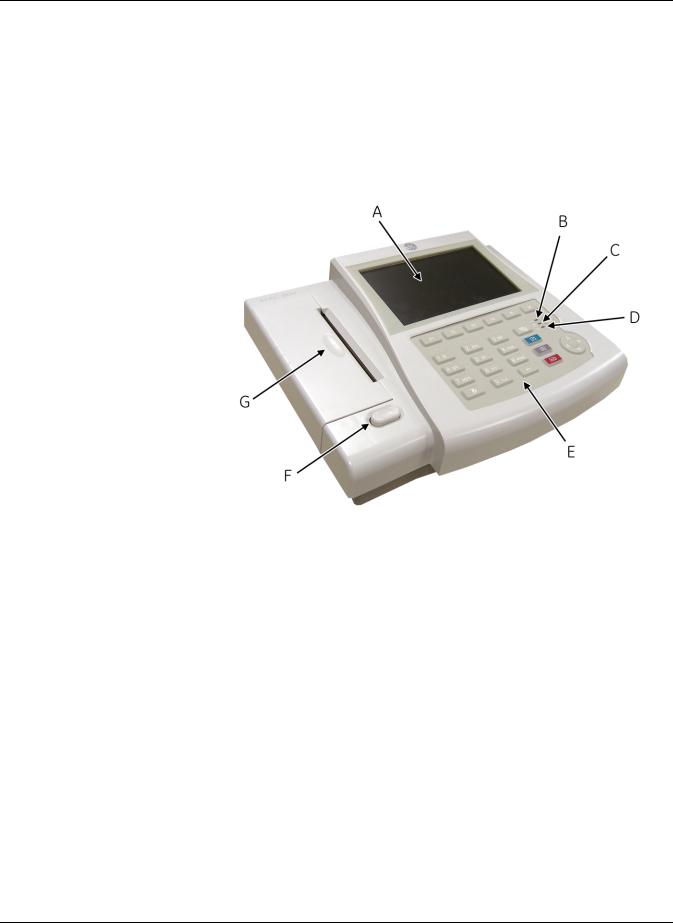
The MAC™ 800 is a 3- and 6-lead print, 12-channel display system with a 7 inch (17.78 cm) diagonal display, active patient cable, battery operation, and options for communication capabilities.
Front View
|
Name |
Description |
|
|
|
A |
Screen |
Displays waveform and text data. |
|
|
|
B |
AC LED |
Indicates when the unit is connected to AC power. |
|
|
|
C |
Battery LED |
Indicates current battery status. |
|
|
Solid indicates the battery is charging. |
|
|
Flashing indicates the battery is low. |
|
|
Off indicates the battery is fully-charged or is |
|
|
discharging but not at a low state. |
|
|
|
D |
Power LED |
Indicates when the unit is powered on. |
|
|
|
E |
Keypad |
Controls the system or enters data. See “Keypad” on |
|
|
page 2-4 for more information. |
|
|
|
F |
Writer Door Button |
Opens printer door. |
|
|
|
G |
Writer |
Prints reports. |
|
|
|
2-2 |
MAC™ 800 |
2031504-159B |
Equipment Overview
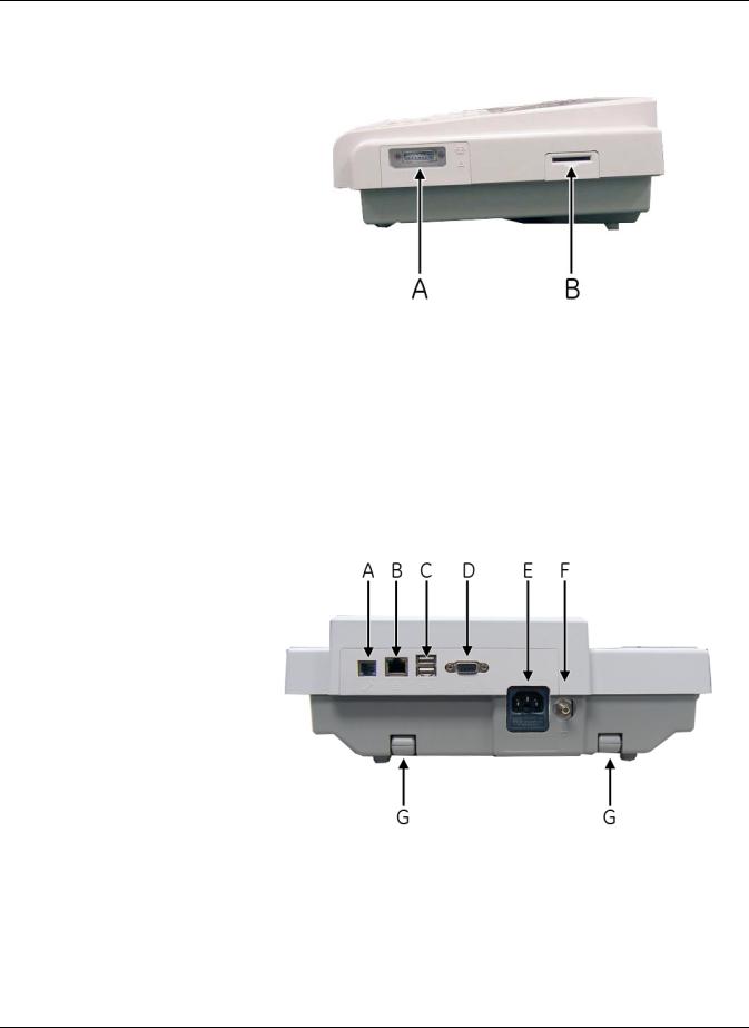
Side View
|
Name |
Description |
|
|
|
A |
ECG signal input connector |
Connects the patient cable to the device. |
|
|
|
B |
Secure digital (SD) card |
Houses the secure digital (SD) card for external |
|
slot |
storage. |
|
|
|
Back View
|
Name |
Description |
|
|
|
A |
Modem port |
Standard RJ-11 jack for connecting the modem to |
|
|
a telephone line. |
|
|
|
2031504-159B |
MAC™ 800 |
2-3 |
Equipment Overview
|
Name |
Description |
|
|
|
B |
LAN port |
Standard RJ-45 jack for connecting the device to a |
|
|
LAN. LEDs on the port indicate status. |
|
|
Solid green indicates a good connection. |
|
|
Flashing amber indicates network traffic. |
|
|
|
C |
USB port |
Universal Serial Bus port used to connect external |
|
|
devices, such as the optional barcode reader. |
|
|
|
D |
COMM port |
Serial port for data communication. Use a serial |
|
|
cable to connect the unit to a CASE/Cardiosoft or |
|
|
MUSE system. |
|
|
|
E |
Main AC power connector |
Connects the unit to an AC power outlet. |
|
|
|
F |
Equipotential grounding lug |
Grounded connector for attaching non-grounded |
|
|
peripheral devices to ensure equipotentiality. |
|
|
|
G |
Carry handle |
Retractable handle for carrying the unit. |
|
|
|
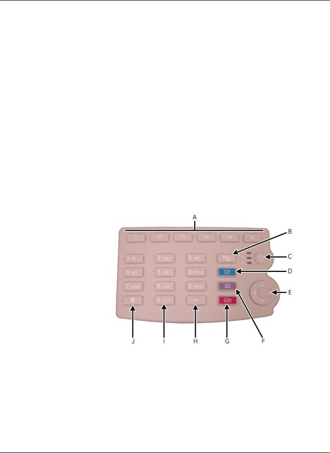
Keypad
The English keypad is shown in the following illustration.
|
Name |
Description |
|
|
|
A |
Function Keys |
Selects menu options on the screen. |
|
(F1 through F6) |
|
|
|
|
B |
Leads key |
Changes the leads when the screen is being used to |
|
|
display waveforms. |
|
|
|
C |
Power Button |
Turns the unit on and off. |
|
|
|
2-4 |
MAC™ 800 |
2031504-159B |

|
|
|
Equipment Overview |
|
|
|
|
|
|
Name |
Description |
|
|
|
|
|
D |
ECG key |
Acquires a resting ECG and prints a 10-second report |
|
|
|
in Arrhythmia mode. |
|
|
|
|
|
E |
Trimpad |
The arrows move the cursor left, right, up, or down. |
|
|
|
The center button moves the focus within a window or |
|
|
|
selects the currently active item. |
|
|
|
|
|
F |
Rhythm key |
Prints a continuous, real-time rhythm ECG strip. Press |
|
|
|
the Stop key to stop the rhythm strip from printing. |
|
|
|
|
|
G |
Stop key |
Stops the writer from printing. |
|
|
|
|
|
H |
Backspace Key |
Deletes characters. |
|
|
|
|
|
I |
Space Key |
Adds a space between typed characters. |
|
|
|
|
|
J |
T9 key |
Switches between different input methods. For more |
|
|
|
information on using the T9 key, refer to the MAC™ |
|
|
|
800 Operator’s Manual. |
|
|
|
|
2031504-159B |
MAC™ 800 |
2-5 |
Equipment Overview
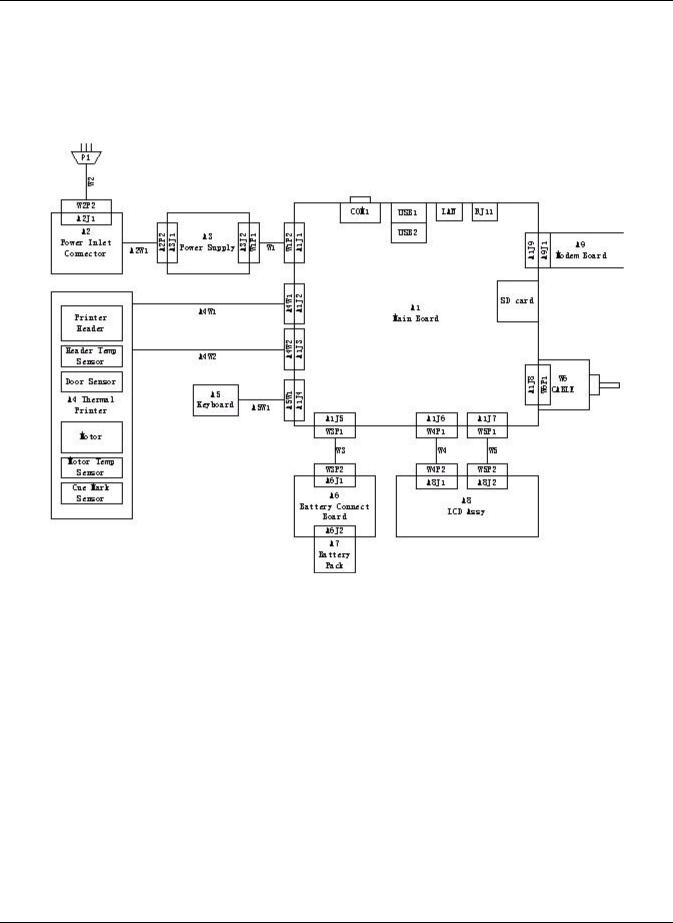
Detailed Description
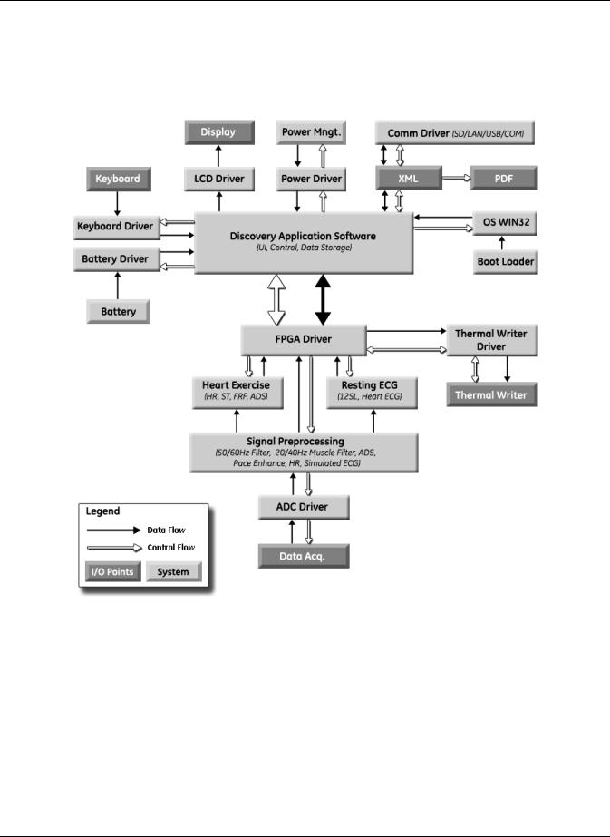
Block Diagram
2-6 |
MAC™ 800 |
2031504-159B |
Equipment Overview
System Architecture
Overview
2031504-159B |
MAC™ 800 |
2-7 |

Equipment Overview
Hardware/firmware Architecture
The MAC 800 hardware and firmware subsystems include the following:
Hardware Subsystems |
Firmware Subsystems |
CPU core |
CE BSP (Board-Support-Package) |
Display |
Printer API |
Keyboard |
Printer SW (Firmware for the Printer) |
ECG Acquisition subsystem |
Acquisition API |
Thermal printer |
Acquisition SW (Firmware for the Printer) |
Power supply |
|
Housing |
|
Product Interfaces
The MAC 800 system offers the following interfaces for connecting to external devices for data communication, software updates, and the control of workload devices:
RS232 port (1)
Connects to external systems, like MUSE or Cardiosoft.
RJ-45 port (1)
Connects to networks via 100baseT ethernet connector via an external medical isolator.
USB connector(2)
Connects to USB-capable devices, such as optional barcode reader or external USB keyboard.
Secure Digital (SD) Card slot
Interfaces with a Secure Digital card, which is used to store ECGs, to flash the device with software updates, and to connect memory / future IO extensions.
RJ-11 port (1)
Connects an internal medical grade Analog Modem (optional) to a phone line.
2-8 |
MAC™ 800 |
2031504-159B |
Equipment Overview
Software Architecture
Layered Structure of application software
2031504-159B |
MAC™ 800 |
2-9 |

Equipment Overview
ECG Data Flow With Sampling Rates
2-10 |
MAC™ 800 |
2031504-159B |

3 Troubleshooting
2031504-159B |
MAC™ 800 |
3-1 |

Troubleshooting
General Fault Isolation
Power-Up Self-Test
See the MAC™ 800 Operator’s Manual, Chapter 2, “Equipment
Overview: Getting Started” to verify operation.
On power-up, the system automatically runs an internal self-test. If all circuit tests pass, you will see the start-up screen.
The next screen that appears after the start-up screen depends on the
Power Up mode selected in System Configuration. The Resting ECG mode is the default Power Up mode.
If the equipment is not working properly, ask the following questions.
Is the unit turned on?
Have there been any changes in the use, location, or environment of the equipment that could cause the failure?
Has the equipment hardware or software been modified since last use?
Is operator error the cause of the problem?
Try to repeat the scenario exactly and compare that to the proper operation of the equipment described in the manual.
Is the battery installed?
When connected to the AC wall outlet, does the green AC power light glow?
Poor Quality ECGs
Poor quality ECGs can be caused by factors in the environment, inadequate patient preparation, hardware failures related to the acquisition module, lead wires, cables, or problems in the unit.
3-2 |
MAC™ 800 |
2031504-159B |

Troubleshooting
Visual Inspection
A thorough visual inspection of the equipment can save time. Small things—disconnected cables, foreign debris on circuit boards, missing hardware, loose components—can frequently cause symptoms and equipment failures that may appear to be unrelated and difficult to track.
NOTE
Take the time to make all the recommended visual checks before starting any detailed troubleshooting procedures
If the area is… |
Look for… |
|
|
I/O Connectors and Cables |
Fraying or other damage |
AC power cord |
Bent prongs or pins |
|
Cracked housing |
|
Loose screws in plugs |
|
|
Interface cables |
Excessive tension or wear |
|
Loose connection |
|
Strain reliefs out of place |
|
|
Circuit boards |
Moisture, dust, or debris (top and bottom) |
|
Loose or missing components |
|
Burn damage or smell of over-heated components |
|
Socketed components not firmly seated |
|
PCB not seated properly in edge connectors |
|
Solder problems: cracks, splashes on board, incomplete |
|
feedthrough, prior modifications or repairs |
|
|
Ground wires/Wiring |
Loose wires or ground strap connections |
|
Faulty wiring |
|
Wires pinched or in vulnerable position |
|
|
Fasteners |
Loose or missing screws or other hardware, especially |
|
fasteners used as connections to ground planes on PCBs |
|
|
Power source |
Faulty wiring, especially AC outlet |
|
Circuit not dedicated to system |
|
NOTE |
|
Power source problems can cause static discharge, |
|
reading problems, and discharge. |
|
|
Keyboard |
Cuts or cracks in the keyboard membrane |
|
Unreadable labels |
|
|
LCD display filter |
Scratches or cracks in the display filter (transparent part of |
|
keyboard bezel) that impair viewing |
|
|
Battery pack |
Cracks, swells, or leaks in the battery casing |
|
Dirt, scratches, or debris on contacts |
|
|
SD card |
Cracks |
|
Dirt, scratches, or debris on contacts |
|
|
2031504-159B |
MAC™ 800 |
3-3 |
Troubleshooting
Event Logging
Setting Up Event Logging
The MAC 800 system can be set up to create an XML-format Event Log that contains system errors, warnings, and informational messages. Use the following procedure to configure the level of severity of messages written to the Event Log.
1.Power on the MAC 800 system by pressing the Power button.
2.From the Main Menu, press F4 to select System Configuration.
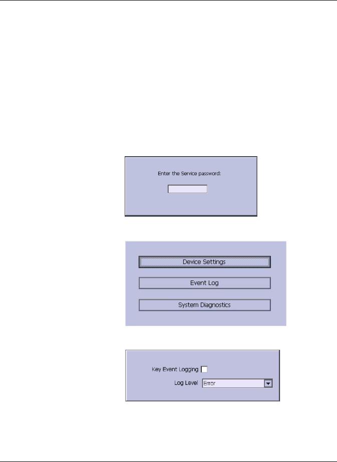
3.Press F6 (More) > F6 (More) > F5 (Service Setup).
The following window prompts you to enter the Service password.
4. Type 7763 and press F6 to select OK to open the Service Setup menu.
5. Move the focus to the Event Log button and press the Enter key.
6.Do one of the following:
To enable event logging, check the Key Event Logging check box.
To disable event logging, clear the Key Event Logging check box.
3-4 |
MAC™ 800 |
2031504-159B |

Troubleshooting
7.Select a level of severity to log from the Log Level list:
Select None to log nothing to the Event Log.
Select Error to log only errors to the Event Log.
Select Warning to log errors and warnings to the Event Log.
Select Information to log errors, warnings, and information messages to the Event Log.
8.Press F6 to select Save.
Exporting the Event Log
1.Repeat step 1 through step 5 in “Setting Up Event Logging” on page 3-4.
2.Insert an SD card (gold contacts down) into the SD card slot as shown in the following illustration.
3.Press F1 to select Export Log Files.
The current Event Log file, log_0.log, is copied to a log directory on the SD card.
NOTE
To access the log file, insert the SD card into an SD card reader connected to a computer with a Windows operating system and open the log file with a text editor like Notepad or WordPad. If the Event Log is requested by GE Service for troubleshooting an issue, the file can be sent as an email attachment.
Performing Diagnostic Tests
Diagnostic tests can be used to verify that the MAC™ 800 operates properly. The tests check the operation of the display screen, speaker, keyboard, thermal writer, battery, and communications. They are useful tools for troubleshooting problems and can be useful as a part of system checkout procedures.
2031504-159B |
MAC™ 800 |
3-5 |
Troubleshooting
Accessing the System Diagnostics Function
The System Diagnostics menu can be used to perform functional diagnostic tests. Use the following procedure to access the System Diagnostics menu.
1.Power on the MAC 800 system by pressing the Power button.
2.From the Main Menu, press F4 to select System Configuration.
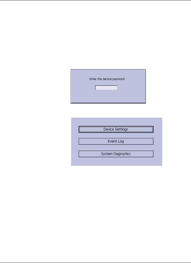
3.Press F6 (More) > F6 (More) > F5 (Service Setup).
The following window prompts you to enter the Service password.
4. Type 7763 and press F6 to select OK to open the Service Setup menu.
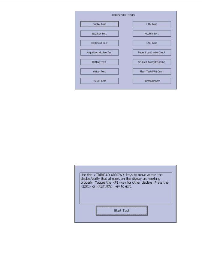
5.Move the focus to the System Diagnostics button and press the Enter key to open the Diagnostic Tests window.
3-6 |
MAC™ 800 |
2031504-159B |
Troubleshooting
The following sections describe how to perform the specific diagnostic tests. Proceed to the appropriate section for the test you need to perform.
Display Test
The Display Test can be used to determine if the display pixels are working properly.
1.Open the Diagnostic Tests window as described in “Accessing the System Diagnostics Function” on page 3-6.
2.Select the Display Test button. The following window opens.
3.Select the Start Test button. The following window opens.
2031504-159B |
MAC™ 800 |
3-7 |

Troubleshooting
4.Press the right arrow key on the Trimpad repeatedly to move the color bars horizontally across the screen.
5.Verify that the color band pattern (red, green, blue, white) scrolls across the screen.
Pass the test if the pattern is replicated without discoloration.
6.Press the F1 key to switch to horizontal color bars.
7.Press the down arrow key on the Trimpad repeatedly.
8.Verify that the color band pattern (red, green, blue, white) scrolls down the screen.
Pass the test if the pattern is replicated without discoloration.
9.Press the F1 key to switch to cycle through the solid color pane (red, green, blue, white).
For each pane, check for black pixels. Pass the test if no more than four black pixels are observed on any single color pane.
NOTE
A black pixel observed on one pane will probably be observed on every pane.
10.Press Enter when the test is complete. The following window opens.
3-8 |
MAC™ 800 |
2031504-159B |
Loading...