


 Loading...
MAC™ 400 Resting ECG Analysis System Safety and Warnings Guide
© 2007, 2008 General Electric Company. All Rights Reserved
The MAC™ 400 Resting ECG Analysis System Safety and Warnings Guide provides guide details, safety information and symbols definitions.
Guides information
The MAC 400 Resting ECG Analysis System Guides contain the instructions necessary for operating the MAC 400 system in accordance with its function and intended use.
The information in these guides only applies to MAC 400 system software version 1. It does not apply to earlier software versions. Due to continuing product innovation, specifications in these guides are subject to change without notice.
MAC™ and Mactrode™ are trademarks owned by GE Medical Systems Information Technologies, a General Electric Company going to market as GE Healthcare. All other marks are owned by their respective owners.
INTENDED AUDIENCE
The MAC 400 Resting ECG Analysis System Guides are intended for persons who use, maintain, or troubleshoot this equipment.
REVISION HISTORY
The document part number and revision letter are on the bottom of each page. The revision letter identifies the document’s update level.
Revision History 2032589-001
Revision |
Date |
Comment |
|
A |
15 |
May 2007 |
Initial release of document |
B |
15 |
June 2007 |
Revised per MVP feedback |
C |
16 |
July 2007 |
Revised IPD |
D |
11 September 2007 |
Revised heading. |
|
E |
17 |
March 2008 |
Updated “Equipment Symbols”. |
PRODUCT REFERENCE
The product described in these guides is the MAC 400 resting ECG analysis system. It may be referred to as “the system” throughout these documents.
CONVENTIONS
These conventions are used in the MAC 400 system guides:
Bold text |
Indicates keys on the keyboard, text to be entered, or |
|
hardware items such as keys or switches on the |
|
equipment. |
|
|
Italicized text |
Indicates terms that identify menu items or options in the |
|
system display window. |
|
|
CE marking information
The MAC 400 system bears the CE mark “CE-0459”, notified body GMED, indicating its conformity with the provisions of the Council Directive 93/42/EEC, concerning medical devices and fulfills the essential requirements of Annex I of this directive. The system delivers 3-channel ECG recordings in automatic and arrhythmia modes and 1 or 3-channel ECG recordings in manual mode. The country of manufacture can be found on the equipment labeling.
The safety and effectiveness of this device have been verified against previously distributed devices. All standards applicable to presently marketed devices may not be appropriate for prior devices (for example, electromagnetic compatibility standards). This device will not impair the safe and effective use of previously distributed devices.
NOTE: Electromagnetic compatibility information can be found in the “MAC™ 400 Resting ECG Analysis System Service Manual”.
Product use and classification
RECOMMENDATIONS
Operating the system near radio frequency (RF) electromagnetic interference (EMI) above the conditions defined in the electromagnetic compatibility (EMC) Standard EN60601-1-2 for Radiated Immunity (field strengths above 3 volts per meter) may cause waveform distortions. Portable and mobile RF communications equipment can affect medical electrical equipment. Users should consider RF sources, such as radio or TV stations and hand-held or mobile two-way radios, when installing a medical device or system. Adding accessories or components, or modifying the medical device or system may degrade the EMI performance. Consult with qualified personnel regarding changes to the system configuration.
Medical electrical equipment requires precautions regarding EMC and needs to be installed and used according to the EMC information provided in the product service manual. The use of accessories, transducers and cables other than those specified or sold by the manufacturer may result in increased emissions or decreased immunity of the system. The system should not be used nearby or stacked with other equipment. If stacking or using near other equipment cannot be avoided, observe to verify normal operation. Review the AAMI Committee Technical Information Report (TIR) 18, “Guidance on Electromagnetic Compatibility of Medical Devices for Clinical/Biomedical Engineers” for details on evaluating and managing an EMI environment in the hospital. Take the following actions to reduce the risk of medical device EMI and achieve EMC:
•Assess the EMC environment of the facility and identify radio transmitters and/or areas where critical medical devices are used such as the emergency room and intensive care units.
•Increase the distance between sources of EMI and susceptible devices.
•Remove the devices that are highly susceptible to EMI.
•Lower the power transmitted from electrical and electronic equipment (EMI sources) under hospital control (i.e. paging systems).
•Label devices susceptible to EMI.
•Educate facility staff (nurses and doctors) to identify, and recognize, potential EMI-related problems.
CLASSIFICATION
The device is classified, according to IEC 60601-1, as:
Type of protection against |
Class I or internally powered equipment. |
electrical shock |
|
|
|
Degree of protection against |
Type CF defibrillation-proof applied part. |
electrical shock |
|
|
|
Degree of protection against |
Ordinary equipment (enclosed equipment |
harmful ingress of water |
without protection against ingress of water, |
|
IPX0). |
|
|
Degree of safety of |
Equipment not suitable for use in the presence |
application in the presence |
of a flammable anesthetic mixture with air or |
of a flammable anesthetic |
with oxygen or nitrous oxide. |
mixture with air, oxygen or |
|
nitrous oxide |
|
|
|
Methods of sterilization or |
Not applicable. |
disinfection recommended |
|
by the manufacturer |
|
|
|
Mode of operation |
Continuous operation. |
|
|
RESPONSIBILITY OF THE MANUFACTURER
GE is responsible for the effects of safety, reliability, and performance only if:
•Assembly operations, extensions, readjustments, modifications, or repairs are carried out by persons authorized by GE.
•The electrical installation of the relevant room complies with the requirements of the appropriate regulations.
•The equipment is used in accordance with the instructions for use.
INTENDED USE
The MAC 400 device is for use under the direct supervision of a licensed healthcare practitioner. The system is intended to acquire, measure and record information from adult and pediatric populations. The basic system delivers 3-channel ECG recordings in automatic and arrhythmia modes and 1 or 3-channel ECG recordings in manual mode. The arrhythmia detection provides the convenience of automatic documentation. It is not designed to provide alarms for arrhythmia detection. This system is not intended for use as a vital signs physiological monitor, or for use during patient transport.
This device is not intended for use with high frequency surgical units. Disconnect the patient from the device before using the high frequency surgical units. This device is not intended for use with direct cardiac applications.
BIOCOMPATIBILITY
The parts of the product described in these guides, including all accessories, that come in contact with the patient during the intended use, fulfill the biocompatibility requirements of the applicable standards. Please contact GE or its representatives with any questions.
Safety information
DEFINITIONS
The terms danger, warning, and caution are used in these guides to point out hazards and to designate a degree or level of seriousness. Familiarize yourself with their definitions and significance. A hazard is defined as a source of potential injury to a person.
DANGER indicates an imminent hazard which, if not avoided, will result in death or serious injury.
WARNING indicates a potential hazard or unsafe practice which, if not avoided, could result in death or serious injury.
CAUTION indicates a potential hazard or unsafe practice which, if not avoided, could result in personal injury or product/property damage. NOTE provides application tips or other useful information to ensure that you get the most from your equipment.
The safety information given in this manual is classified as follows.
Warning |
Description |
|
|
Accidental spills |
To avoid electric shock or device malfunction, liquids |
|
must not enter the device. |
|
If liquids enter the device, stop using it and have it |
|
checked by a service technician before further use. |
|
|
Battery |
If the integrity of the protective earth conductor is in |
operation |
doubt, operate the unit from its battery. |
|
|
Cables |
To avoid possible strangulation, route all cables away |
|
from patient's throat. |
|
|
Connection to |
This is Class I equipment. The mains plug must be |
mains |
connected to an appropriate power supply. |
|
|
Warning |
Description |
|
|
Defibrillator |
Do not come into contact with patients during |
precautions |
defibrillation. Serious injury or death could result. Patient |
|
signal inputs labeled with the CF and BF symbols with |
|
paddles are protected against damage resulting from |
|
defibrillation voltages. To ensure proper defibrillator |
|
protection, use only the recommended cables and lead |
|
wires. Proper placement of defibrillator paddles in |
|
relation to the electrodes is required to ensure successful |
|
defibrillation. |
|
|
Electrodes |
Polarizing electrodes (stainless steel or silver |
|
constructed) may cause the electrodes to retain a residual |
|
charge after defibrillation. A residual charge will block |
|
acquisition of the ECG signal. Whenever patient |
|
defibrillation is a possibility, use nonpolarizing (silver/ |
|
silver chloride construction) electrodes for ECG |
|
monitoring. |
|
|
Magnetic and |
Magnetic and electrical fields can interfere with proper |
electrical |
performance of the device. Make sure that all external |
interference |
devices operated near the device comply with the relevant |
|
EMC requirements. |
|
X-ray equipment or MRI devices may interfere with |
|
system performance because they may emit higher levels |
|
of electromagnetic radiation. |
|
|
Explosion |
Do NOT use in the presence of flammable anesthetics |
hazard |
vapors or liquids. |
|
|
Interpretation |
Computerized interpretation is only significant when |
hazard |
used in conjunction with clinical findings. A qualified |
|
physician must over read all computer generated tracings. |
|
|
Operator |
Medical technical equipment such as this |
|
electrocardiograph system must only be used by persons |
|
who have received adequate training in the use of such |
|
equipment and are capable of applying it properly. |
|
|
Shock hazard |
Improper use of this device presents a shock hazard. |
|
Failure to observe the following warnings may endanger |
|
the lives of the patient, the user, and bystanders. |
|
Disconnect from the power source before disconnecting |
|
the cable from the device to reduce the risk of |
|
inadvertently introducing metal parts in the sockets of the |
|
power cord and coming in contact with line voltage. |
|
|
Site |
Do not route cables in a way that they may present a |
requirements |
stumbling hazard. For safety reasons, connectors for |
|
patient cables and lead wires are designed to prevent |
|
disconnection if pulled on. For devices installed above |
|
the patient, adequate precautions must be taken to prevent |
|
them from dropping on the patient. |
|
|
MAC™ 400 resting ECG analysis system guides |
1 of 7 |
2032589-001 |
Revision E |

MAC™ 400 Resting ECG Analysis System Safety and Warnings Guide
© 2007, 2008 General Electric Company. All Rights Reserved
Caution |
Description |
|
|
Accessories |
To ensure patient safety, use only parts and accessories |
(supplies) |
manufactured or recommended by GE. Parts and |
|
accessories must meet the requirements of the |
|
applicable IEC 60601 series safety standards and |
|
essential performance standards. |
|
|
Proper lead wire |
Improper connection will cause inaccuracies in the |
connection |
ECG. Trace each individual lead wire from its |
|
acquisition module label to the colored connector and |
|
then to the proper electrode to ensure that it is matched |
|
to the correct label location. |
|
|
Before installation |
Compatibility is critical to safe and effective use of |
|
this device. Please contact your local sales or service |
|
representative prior to installation to verify equipment |
|
compatibility. |
|
|
Disposables |
Disposable devices are intended for single use only. |
|
Do NOT reuse, as performance may degrade or |
|
contamination could occur. |
|
|
Equipment damage |
Devices intended for emergency application must not |
|
be exposed to low temperatures during storage and |
|
transport to avoid moisture condensation at the |
|
application site. Wait until all moisture has vaporized |
|
before using the device. |
|
|
Electric shock |
To reduce the risk of electric shock, do NOT remove |
|
cover (or back). Refer servicing to qualified personnel. |
|
|
Power |
Before connecting the device to the power line, check |
requirements |
that the voltage and frequency ratings of the power |
|
line are the same as those indicated on the unit's label. |
|
If not, do not connect the system to the power line. |
|
This equipment is suitable for connection to public |
|
mains as defined in CISPR 11. |
|
|
Low battery shut |
If the battery is not charged for a long enough period |
down |
of time or after multiple attempts to power on |
|
following a low-battery shut down, the system shifts |
|
to a second level of deep discharge protection. If |
|
device is turned on, it might call for a 1 to 2 minute |
|
continuous self test. Charge the battery for a minimum |
|
of half an hour before using device. We recommend |
|
that you keep the unit charged to avoid a low-battery |
|
shut down. |
|
|
Serviceable parts |
This equipment contains no user serviceable parts. |
|
Refer servicing to qualified service personnel. |
|
|
Supervised use |
This equipment is intended for use under the direct |
|
supervision of a licensed healthcare practitioner. |
|
|
General information
RECORDING ECGS DURING DEFIBRILLATION
This equipment is protected against the effects of cardiac defibrillator discharge to ensure recovery, as required by test standards. The patient signal input of the acquisition module is defibrillation-proof. It is not necessary to remove the ECG electrodes prior to defibrillation. When using stainless steel or silver electrodes, a defibrillator discharge current may cause the electrodes to retain a residual charge causing a polarization or DC offset voltage. Electrode polarization blocks acquisition of the ECG signal. If a defibrillation procedure is necessary, use non-polarizing electrodes, such as silver/silver-chloride types, to avoid a DC offset voltage when subjected to a DC current. If using polarizing electrodes, disconnect the lead wires from the patient before delivering the shock. Electrode defibrillation recovery allows the ECG trace to return after defibrillation. We recommend using nonpolarizing disposable electrodes with defibrillation recovery ratings as specified in AAMI EC12 3.2.2.4. (MMS P/N 9623-103P Silver Mactrodes™, MMS spec. TP9623-003). AAMI EC12 requires that the polarization potential of an electrode pair does not exceed 100 mV, five seconds after a defibrillation discharge.
RECORDING ECGS OF PACEMAKER PATIENTS
The system does not support pacer pulse detection.
WARNING: PATIENT HAZARD — If several adverse conditions exist at once, pacer pulses might be interpreted and counted as QRS complexes. Pacemaker patients should always be watched closely.
ACCURACY OF THE INPUT SIGNAL REPRODUCTION
•Overall system error is tested using the method described in AAMI EC11 3.2.7.1. Overall system error is ±5 %.
•Frequency response is tested using the method described in AAMI EC11 3.2.7.2 methods A and D.
MODULATING EFFECTS IN DIGITAL SYSTEMS
This device uses digital sampling techniques that may produce some variation in amplitudes of Q, R, and/or S waves from one heart beat to the next. These variations may occur more in pediatric recordings. If this variation is observed, be aware that the origin of amplitude variations is not entirely physiologic. For measuring voltages of Q, R, and S waves, use the QRS complexes with the largest deflection of the particular waves.
PARTS AND ACCESSORIES
To ensure patient safety, use only parts and accessories manufactured or recommended by GE. Parts and accessories must meet the requirements of the applicable IEC 60601 series safety standards and essential performance standards.
EQUIPMENT SYMBOLS
Symbol |
Description/Function |
Type CF equipment. The acquisition module is protected from defibrillation shocks.
The flashing yellow LED indicates you must connect to AC power to re-charge the battery.
Consult instructions for use.
Consult accompanying documents for cautions.
Classified with respect to electric shock, fire, mechanical, and other specified hazards only in accordance with UL 60601-1, CAN/CSA C22.2
No. 601.1, EN 60601-2-25, EN 60601-1, IEC 60601-1-2: 2001, IEC 60601-2-51.
Indicates that the device is classified as Ordinary Equipment (enclosed equipment without protection against ingress of water).
Indicates that the waste of electrical and electronic equipment must not be disposed as unsorted municipal waste and must be collected separately. Please contact an authorized representative of the manufacturer for information concerning the decommissioning of your equipment.
Fuse.
Do not throw or dispose of in fire!
Contains "Lithium Ion". This symbol indicates "General recovery/recyclable" and must not be disposed of as unsorted municipal waste and must be collected separately.
Manufacturer name and address.
Date of Manufacture (Year-Month).
Batch code of paper or battery.
Catalogue number (Part number).
Symbol |
Description/Function |
Serial number.
European authorized representative.
The packaging of this product can be recycled.
Humidity limitation.
Atmospheric pressure limitation.
Environment-friendly Use Period per Chinese standard SJ/
T11363-2006 (China specific).
PCT. GOST marking symbolizing conformity with applicable Russian Gosstandart technical and safety standards.
SERVICE REQUIREMENTS
Refer equipment servicing to GE authorized service personnel only. Any unauthorized attempt to repair equipment under warranty voids that warranty. It is the user’s responsibility to report the need for service to GE or an authorized agent.
EQUIPMENT IDENTIFICATION
Every GE device has a unique serial number for identification on the device label.
A |
Product code is SCT |
|
B |
Year manufactured (00-99) |
|
00 = 2000, 01 = 2001, and so on |
||
|
||
|
|
|
C |
Fiscal week manufactured |
|
D |
Production sequence number |
|
E |
Manufacturing site |
|
F |
Miscellaneous characteristic |
g
GE Medical Systems |
|
Asian Headquarters |
Information |
|
GE Medical Systems |
Technologies, Inc. |
|
Information Technologies Asia; |
8200 West Tower |
GE Medical Systems |
GE (China) Co., Ltd. |
Avenue |
Information Technologies |
11th Floor Shanghai MAXDO |
Milwaukee, WI 53223 USA |
GmbH |
Centre |
Tel: + 1414 355 5000 |
Munzinger Strabe 3-5 |
8 Xing Yi Road, Hong Qiao |
1 800 558 5120 (US only) |
D-79111 Freiburg |
Development Zone |
Fax: + 1414 355 3790 |
Germany |
Shanghai 200336, People’s |
|
Tel: + 49 761 4543 - 0 |
Republic of China |
www.gehealthcare.com |
Fax: + 49 761 4543 - 233 |
Tel: + 86-21-5257-4650 |
MAC™ 400 resting ECG analysis system guides |
2 of 7 |
2032589-001 |
Revision E |
MAC™ 400 Resting ECG Analysis System Installation and Setup Guide
© 2007, 2008 General Electric Company. All rights reserved.
The MAC™ 400 Resting ECG Analysis System Installation and Setup Guide provides instructions for initial installation and setup of your system.
Before you begin
Remove the device and accessories from the box, and keep on a flat dry surface, away from direct sunlight, heat sources & dust.
A.Confirming the box contents
•MAC 400 resting ECG analysis device
•Four limb clamp electrodes
•Six bulb electrodes
•Patient ECG cables/lead wires
•Power cable
•Pack of z-fold paper (280 sheets)
•Electrode cream
•CD containing a service manual and 12SL™ Physicians Guide
•User guide
B.Charging the battery
The MAC 400 system needs a charged battery to print an ECG. Charge the battery for three hours for full power. A fully charged battery allows for 100 automatic mode ECGs or 100 minutes of arrhythmia/ manual mode recording.
1.Connect the device to a power source.
2.Turn on the power (a green light indicates that AC mains is connected).
3.After charging for three hours, unplug the power cord from both the device and the power source.
Recharge when you see a yellow light above the power key.
C. Loading paper
The MAC 400 system supports the use of standard thermal recording paper in either z-fold pads or roll paper.
1.Locate the printer assembly.
2.Gently pull back the printer assembly door to open the door latch.
3.Open the z-fold paper pack.
4.Ensure that the black paper guide is on the top and place the paper in the tray.
5.Advance the first sheet and close the door. Make sure that the paper is positioned on the pressure roller and that the door locks into place on both sides.
A red line at the top of the last ten sheets indicates that the paper supply is low. Change paper as needed.
NOTE: For instructions on loading roll paper, see the “MAC™ 400 Resting ECG Analysis System Maintenance Guide”.
Initial system setup
THE SETUP MENU
Press on/off to turn on the device, and then, press 
configuration to access the setup menu. Use the setup menu to navigate between system settings and select the options you want. For more information, see System Symbols and System Menu Descriptions on page 4.
THE SYSTEM PARAMETERS TOOLS
Use these tools and guidelines to help you define the operating parameters.
1.Use  up/down cursor to select a menu item.
2.Use  right/left cursor to select the desired setting.
3.Always press  enter to confirm your selection.
4.Always press  configuration to save and exit the
setup menu.
SETTING OPTIONS FOR INITIAL USE
A. Selecting a language
Different languages are available for the display text and printed ECG reports.
1.Press  configuration to display the language selection menu.
2.Use the right/left cursor to select the language.
3.Press  enter to confirm your selection.
B. Selecting the lead notations
There are two different lead notation options: AHA and IEC.
1.Use the  up/down cursor to select Notation.
2.Use the  right/left cursor to select AHA or IEC.
3.Press  enter to confirm your selection.
C. Setting the date and time
Set the date and time for printed ECG reports. To set the date:
1. Use the  up/down cursor to select Date.
2.Use the  right/left cursor to set the date.
3.Press enter to confirm your selection.
To set the time:
1.Use the  up/down cursor to select Time.
2.Use the  right/left cursor to set the time.
3.Press  enter to confirm your selection.
D. Selecting heart rate limit values
1.Use the up/down cursor to select HR control. The cursor flashes on the low limit value.
2.Use the  right/left cursor to change the low limit value, in increments of 5 BPM, between 30 and 120 BPM.
3.Press  enter to confirm your selection.
4.Use  right/left cursor, change the high-limit value (between 80 and 240 BPM).
5.Press  enter to confirm.
NOTE: After setting these options, you must press  configuration to save the options and exit the setup menu.
Heart rate indication
THE BASICS
WARNING PATIENT HAZARD — The MAC 400 system is not intended for use as a vital signs physiological monitor. When needed, use a device intended for vital signs monitoring.
When the heart rate indication function is enabled, the automatic switchoff is disabled. Conditions of high and low heart rate are indicated in all operating modes, even when not recording. This function can be disabled in the setup menu. The default heart rate limits are 45 and 130 BPM, and can be modified in the setup menu. If the heart rate exceeds one of the set values, the system emits an audio signal. This audio signal ceases automatically when the heart rate returns to the permitted range or when
you press  QRS beep. The audio signal will not recur if it was
silenced with  QRS beep. The audio signal recurs only when the heart rate exceeds one of the limit values again.
E. Hooking up the starter kit
Once you have customized your settings, connect the patient cable to the device (A) on the right side panel.
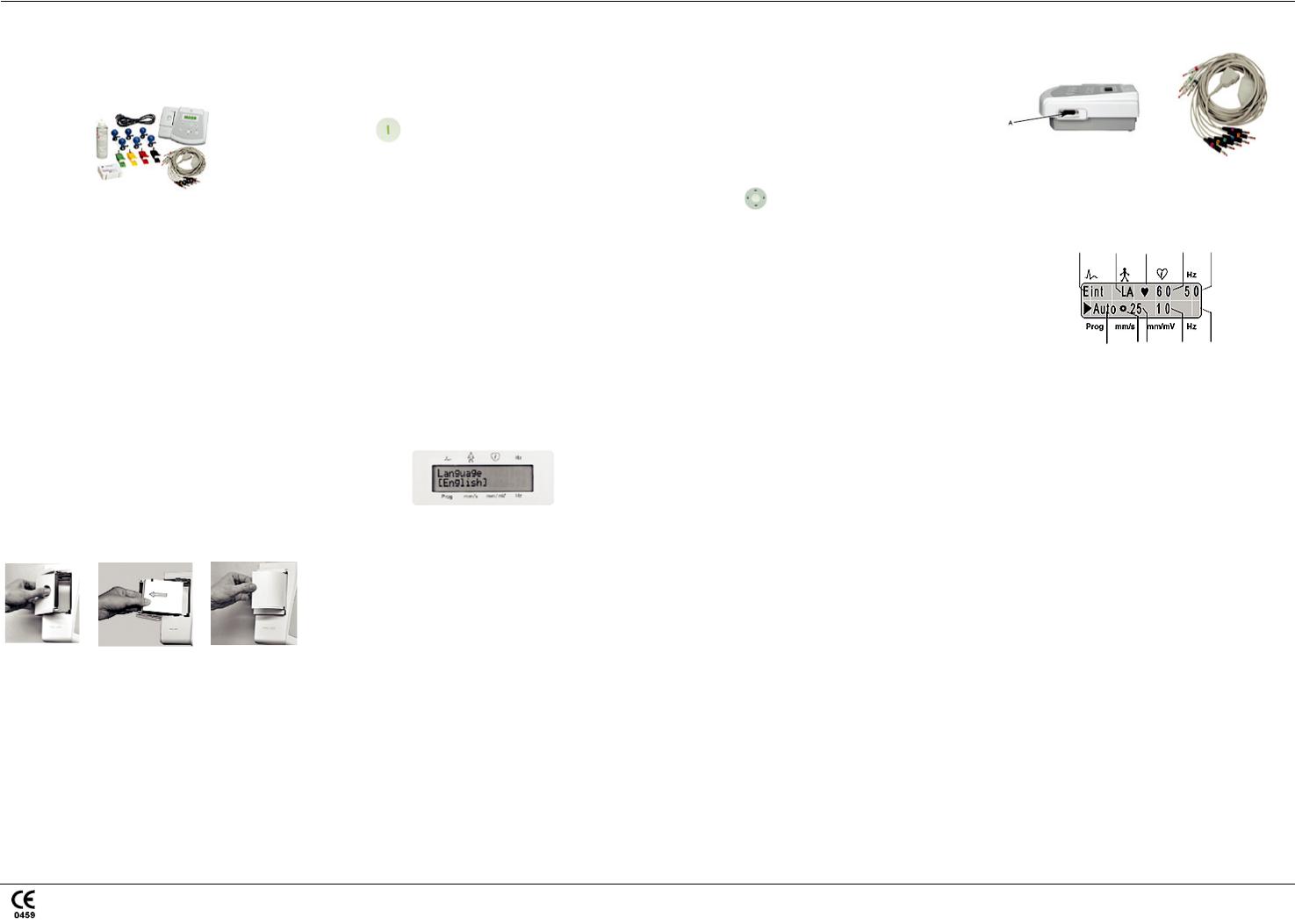
Default settings for auto mode
When you turn on the device, the system default is automatic mode. Factory defaults have the following functions and settings (the most important settings are indicated on the display):
A B C D E
|
J |
I H |
G |
F |
|
|
|||
A |
Lead sequence: Standard = Einthoven (I, II, III), |
|||
Goldberger(aVR, aVL, aVF), Wilson 1 (V1, V2, |
||||
|
V3), Wilson 2 (V4, V5, V6). |
|
||
|
|
|||
B |
Lead fail indicator: Indicates a disconnected |
|||
electrode. For example, LA indicates that the left |
||||
|
arm electrode is disconnected. |
|
||
|
|
|||
C |
QRS indicator: The heart symbol blinks with every |
|||
detected systole. |
|
|
|
|
|
|
|
|
|
|
|
|||
D |
Heart rate: Detects the patient’s heart rate. In this |
|||
example, it is 60 BPM. |
|
|
||
|
|
|
||
|
|
|
||
E |
AC filter: On (enabled) (50 Hz). |
|
||
F |
Muscle filter: Off (disabled). |
|
||
G |
Sensitivity (gain): 10 mm/mV. |
|
||
H |
Paper speed: 25 mm/s. |
|
|
|
I |
Rotating symbol: Displays when the ECG data |
|||
acquisition or recording is active. |
|
|||
|
|
|||
|
|
|
||
J |
Operating mode: Automatic. |
|
||
Additional default settings (not indicated on the display):
•Notation: AHA.
•ADS: Enabled.
•Report format: Simultaneous, short.
•Override: Disabled.
NOTE: For further descriptions of the settings, see System Menu Descriptions on page 4.
MAC™ 400 resting ECG analysis system guides |
3 of 7 |
2032589-001 |
Revision E |
Loading...