


LOGIQ C3
Table of contents
 Loading...
GE Healthcare
Technical
Publications
Direction 5272220-100
Rev. 2
LOGIQ C5/C5 PRO
Quick Guide
Copyright 2008 - 2009 By General Electric Co.
Operating Documentation

Regulatory Requirement
LOGIQ C5/C5 PRO complies with regulatory requirements of the following European Directive 93/42/EEC concerning medical devices.
Manufacturer
GE Medical Systems (China) Co., Ltd.
No. 19 Changjiang Road
Wuxi National Hi-Tech Development Zone
Jiangsu, P.R.China 214028
Tel: +86 510 85225888; Fax: +86 510 85226688
GE Healthcare
GE Medical System: Telex 3797371
P. O. Box 414, Milwaukee, Wisconsin 53201 U.S.A.
(Asia, Pacific, Latin America, North America)
GE Ultraschall:Tel: +33 (0) 130 831 300
Deutschland GmbH & Co KG
Beethovenstrabe 239, Postfach 11 05 60
D-42655 Solingen, Germany

LOGIQ C5/C5 PRO Quick Guide Direction 5272220-100 Rev. 2 A
Please verify that you are using the latest revision of this document. Information pertaining to this document is maintained on MyWorkshop/
ePDM (GE Healthcare electronic Product Data Management). If you need to know the latest revision, contact your distributor, local GE Sales
Representative or in the USA call the GE Ultrasound Clinical Answer Center at 1-800-682-5327 or 262-524-5698.
Revision History
REV
1
2
PAGE REVISION
NUMBER HISTORY
Title Rev. 2
1 Rev. 2
1-52 Rev. 2
DATE
May 23, 2008
Feb.10, 2009
List of Effective Page
REASON FOR CHANGE
New Release
Delete “C5 PRO do not support Clipboard”

LOGIQ C5/C5 PRO Quick Guide Direction 5272220-100 Rev. 2 1
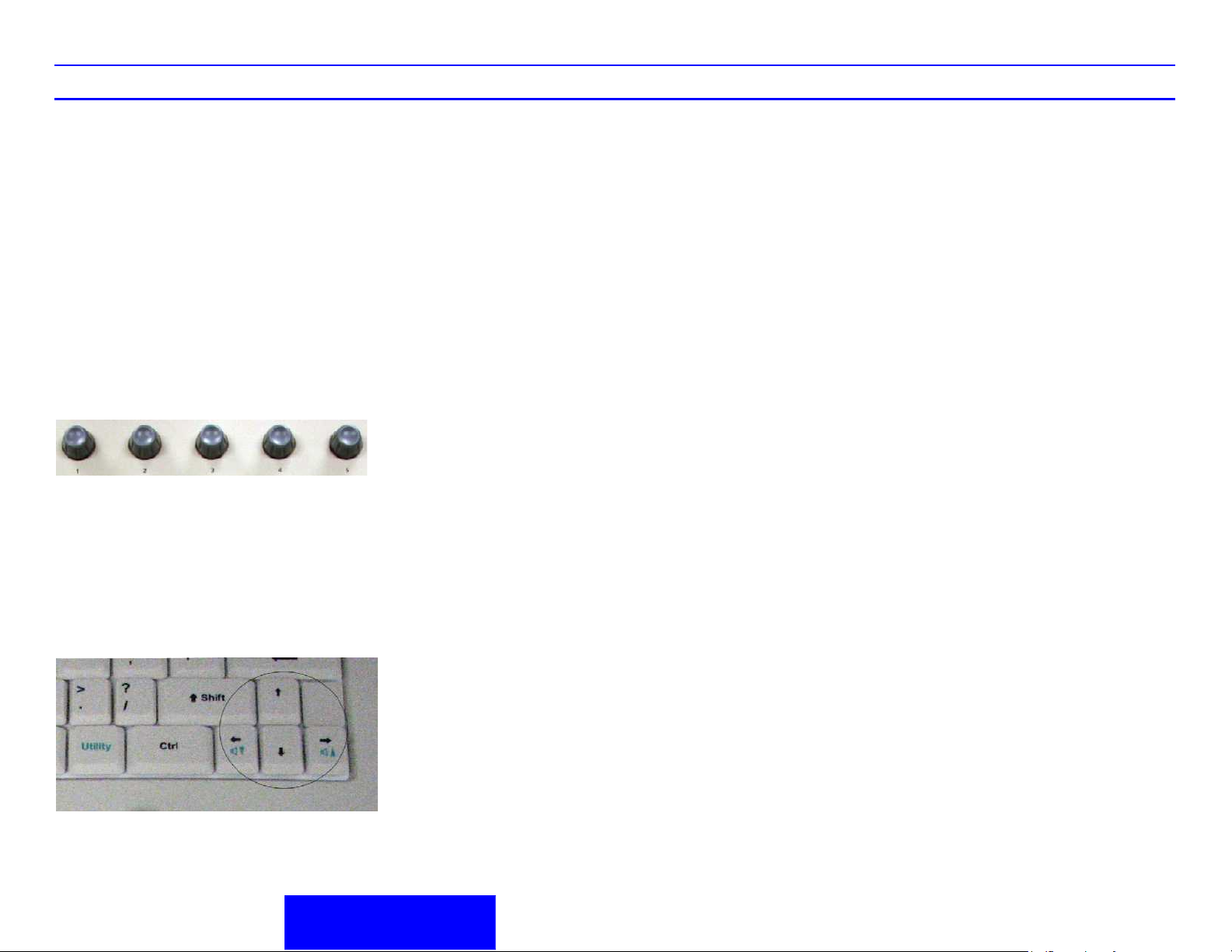
Control Panel Tour
LOGIQ C5/C5 PRO Control Panel Tour
1. Power On/Off Switch
2. Probe Key:switch the probes
3. Top Menu Controls
4.
Keyboard :Use the keyboard to enter
patientinformation and annotations.Press F1,
F2, F3, F4 and F5 keys to activate Online help/
User Manual, Arrow, Eject, Spooler and
activate Sub Menu. The User can define
functions for the F6-F12 keys. The following
functions are available for F6-F12 Keys:
WorkSheet, 3D, LOGIQ View, ECG On/Off, Set
Home, Grab Last, Word delete and Text
Overlay. Press [Utility] to enter the Utility
function and configure the system. Press
[Report] to enter the worksheet
page.Press[End Exam]to end a exam.
5. Preset,PDI,Steer,Harmonics Keys
6. Paitent Key:Use the key to display th paitent
screen
7. Mode Keys: B Mode,M Mode,Pulsed Wave
Doppler (PW) Modes and Color Flow (CF)
Mode .Press these key to activate the mode
13. Left, Right Key:activate the Left or Right
displayed image.
14. Freeze. Press Freeze to freeze the image or
return to scanning.
15. Trackball
16. Imaging/Measurement Key: Cursor, Clear,
Body Mark Measure, M/D Cursor, Scan Area,
Set. Press these keys, as necessary.
17. Time Gain Compensation(TGC):Move slide
pots left/right to adjust TGC.
18. Gel Holder
19. Probe Holder
8. Gain/Auto Key:Rotate the key to adjust the
Gain; Press the key to activate/deactivate auto
optimization.
9. Zoom Key:magnify a zoom region of interest
(ROI).
10. Ellipse Keys: activates the area/ellipse
measurement function.
11. Depth Key:controls the distance over the
images
12. Reverse,Print, Store Key:Reverse key can flips
the image 180 degrees left/right. Print Key can
archive, print, or send the image.Store Key can
save the images to harddisk( factory default)
Figure 1. Control Panel
LOGIQ C5/C5 PRO Quick Guide Direction 5272220-100 Rev. 2 2
Control Panel Tour
LOGIQ C5/C5 PRO Keys
Top/Sub Menu Key Tour
Top Menu Control
In general, there are two types of Top Menu keys:
Paddle Switch and adjustable knobs.
1. Press the adjustable knobs to toggle option
menu between line one and line two.
2. Rotate the adjustable knobs to adjust the
corresponding parameters.
Figure 2. Top Menu Key
Sub Menu Control
1. Press F5 on the keyboard to activate Sub
Menu,
2. Use the Direction keys to toggle/change
functions
Function Keys - Programmable Keys
• F1 = Help (Enter Online Help / User Manual)
• F2 = Arrow (Annotation Arrow)
• F3 = Eject (Eject media)
• F4 = Spooler (Activates DICOM Job Spooler
screen)
• F5 = Activate Sub Menu
• F6 -F12 Programmable
How to Program your programmable
keys
<Utility> - <Admin> - <Function Key>, then use the
drop down menu.
Choices for program Keys
• WorkSheet
•3D
• LOGIQ View
• ECG On/Off
•Set Home
• Text Overlay
• Grab Last
• Word Delete
How to Program your hot keys
<Utility> - <Admin> - <Function Key>, <Hot Key>
then use the drop down menu.
Choices for hot keys
• No function
• Biopsy Guide
• Save as
• Active Image
• Measurement Select
• Auto Doppler Calculation
• Auto Trace
• DVD Format
• Range Focus
•OB Graph
• Measurement All Clear
•ATO
Figure 3. Sub Menu Key
Shortcut keys
• Ctrl + Alt + R: Restart the system
• Ctrl + E: Eject
LOGIQ C5/C5 PRO Quick Guide Direction 5272220-100 Rev. 2 3
Control Panel Tour
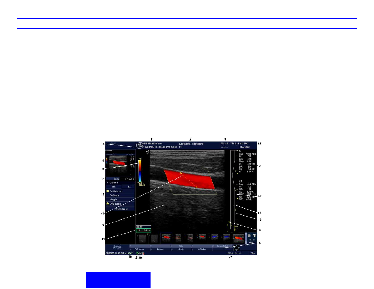
LOGIQ C5/C5 PRO Monitor Display Tour
1. Institution/Hospital Name, Date, Time, Operator
Identification, system status (real-time of
frozen).
2. Patient Name, Patient Identification.
3. Acoustic Output Readout.
4. GE Symbol: Probe Orientation Marker.
Coincides with the probe orientation marking on
the probe.
5. Image Preview.
6. Gray/Color Bar.
7. Cine Gauge.
8. Measurement Summary Window.
9. Image.
10. Measurement (not shown).
11. Measurement Results Window.
12. Probe Identifier. Exam Study.
13. Imaging Parameters by Mode (current mode
highlighted).
14. Focal Zone.
15. TGC (not shown on the image).
16. Body Pattern.
17. Depth Scale.
18. Top/Sub Menu.
19. Caps Lock: On or Off.
20. Start Menu Icon
21. Card iconTrackball Functionality Status: Scroll,
M&A (Measurement and Analysis), Position,
Size, Scan Area Width and Tilt.
22. Trackball Functionality Status: Scroll, M&A
(Measurement and Analysis), Position, Size,
Scan Area Width and Tilt

LOGIQ C5/C5 PRO Quick Guide Direction 5272220-100 Rev. 2 4
System Power
Power On
To connect the system to the electrical supply:
1. Ensure that the wall outlet is of the appropriate
type.
2. Ensure that the protective earth (ground)
connection is reliable.
ACDC Type Specification ACDC Type Specification
220-240VAC
500VA
(China)
220-240VAC
500VA
(India)
220-240VAC
500VA
(Argentina)
220-240 VAC
500VA
(Europe)
100-120 VAC
2.5A
(Denmark)
220-240VAC
500VA
(Switzerland)
220-240VAC
500VA
(U.K.)
100-120 VAC
500VA
(USA)
220-240 VAC
500VA
(Australial)
3. Unwrap the power cable. Make sure to allow
sufficient slack in the cable so that the plug is
not pulled out of the wall if the system is moved
slightly.
Use caution to ensure that the power cable does
not disconnect during system use. If the system is
accidentally unplugged, data may be lost.
Press the Power On/Off switch to turn the power
on.
a
LEDs
1. When connect the system to the electrical
supply,the LED turns amber.
Figure 5. Power LED
2. After pressing the Power On/Off switch,the
system power is on and the LED turns
Green.The Probe Key LED is lit.
Table 1: Example Plug and Outlet Configurations
Figure 6. Power and Probe LED
Figure 4. Power on Bottom
a. Power Switch Location
LOGIQ C5/C5 PRO Quick Guide Direction 5272220-100 Rev. 2 5
Prepare Exam
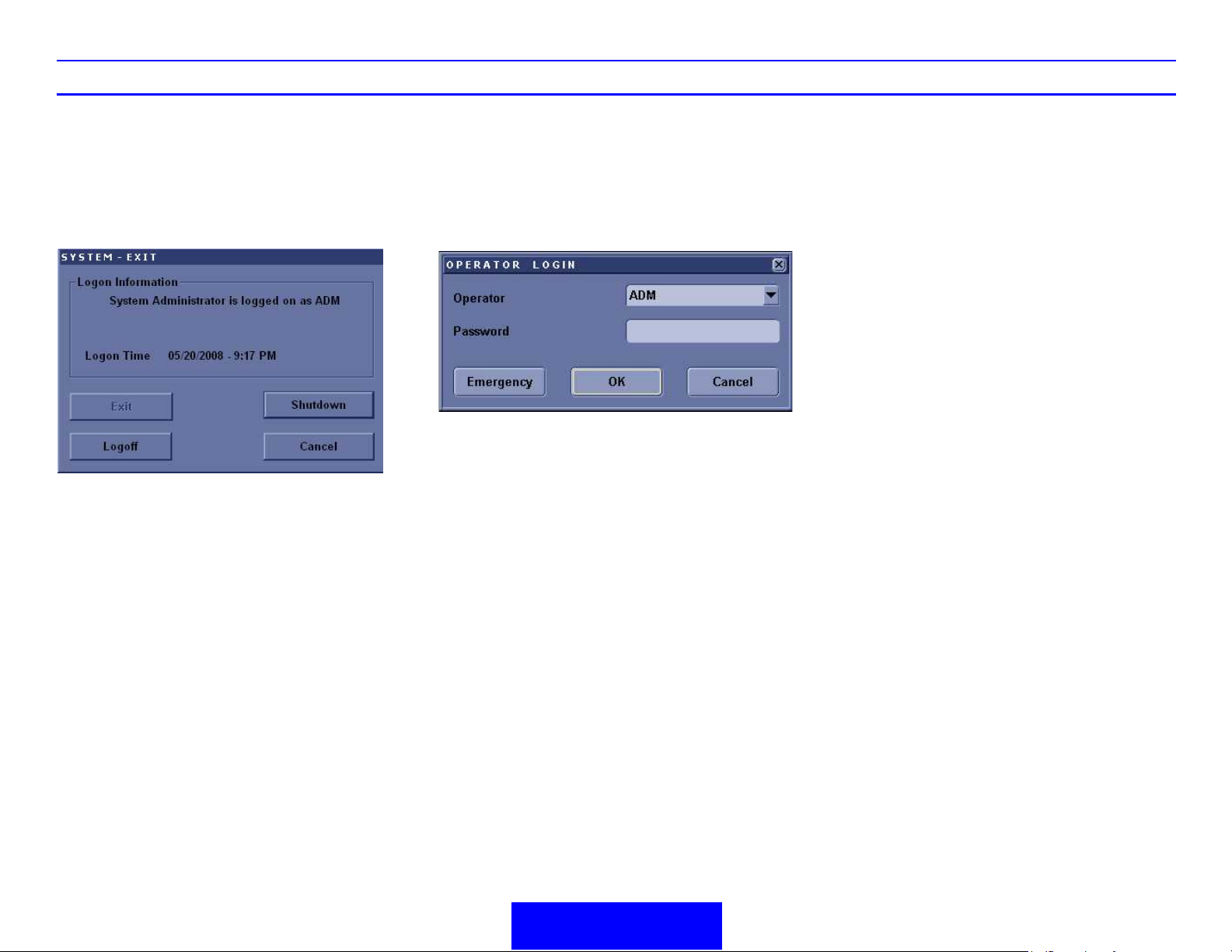
Power Off
To power down the system:
1. Press the Power On/Off switch at the front of
the system once.
2. The System-Exit window is displayed.
Figure 7. Power Off Window
3. Using the Trackball or Select key, select
Shutdown.
The shutdown process takes a few seconds
and is complete when the power LED turns
amber.
4. Disconnect the probes.
Starting an Exam
You need to select a pre-configured dataflow that
sets up the ultrasound system to work according to
the services associated to the dataflow.
1. Select your Operator Login and type in your
Password:
Figure 8. Operator Login Window
2. Press OK.
3. Fill in the New Patient menu as described on
page 1-6.
OR,
If the patient name is on the patient record list,
Trackball to the patient’s name to highlight the
name, (or perform a search to locate the patient).
Clean or disinfect all probes as necessary.
Store them in their shipping cases to avoid
damage.

LOGIQ C5/C5 PRO Quick Guide Direction 5272220-100 Rev. 2 6
Starting an Exam
New Patient
To start a new patient’s exam,
1. Press Patient. Press the New Patient button on
the Patient menu.
2. Select the Exam Category.
3. Type the Patient ID, Patient Name, Birthdate,
etc.
4. Press the Register button on the Patient menu
(DO NOT press Register if you are
automatically generating a patient ID).
5. Press B, Esc, or Exit.
Patient Entry Menu
Image Management Window [1]
Access to this patient’s exam history and image
management features.
Function Selection Window [2]
New Patient is used to clear the patient entry
screen to input a new patient’s data into the
database. Register is used to enter new patient
information into the database prior to the actual
exam being performed. Details displays exam
details and additional patient information.
EZBackup, EZMove [3]
One-step method to backup (move and delete
patient images) to an external media.
Dataflow [4]
Selects this exam’s dataflow preference.
Exit [5]
Exits the Patient Menu and returns to scanning.
Patient Information [6]
Patient ID, Name, Birthdate, Age and Sex.
Category Selection and Exam Information [7&8]
Select the appropriate category and enter the exam
information.
Patient View and Exam View [9]
Patient View lists the patients in the database.
“Search key” enables searching list by Patient ID,
Last Name, First Name, Birthdate, Sex, Exam
today, Exam between, Exam date before,
Examdate, Examdate after, Accession Number and
Exam Description. “string” field helps define the
search parameters, and “Clear“ clears the
searching condition.
Figure 9. Paitent Screen
Exam View lists the exams of the selected patient.
Select the patient or the exam in Patient View and
press “Exam View”.

LOGIQ C5/C5 PRO Quick Guide Direction 5272220-100 Rev. 2 7
B/M Mode
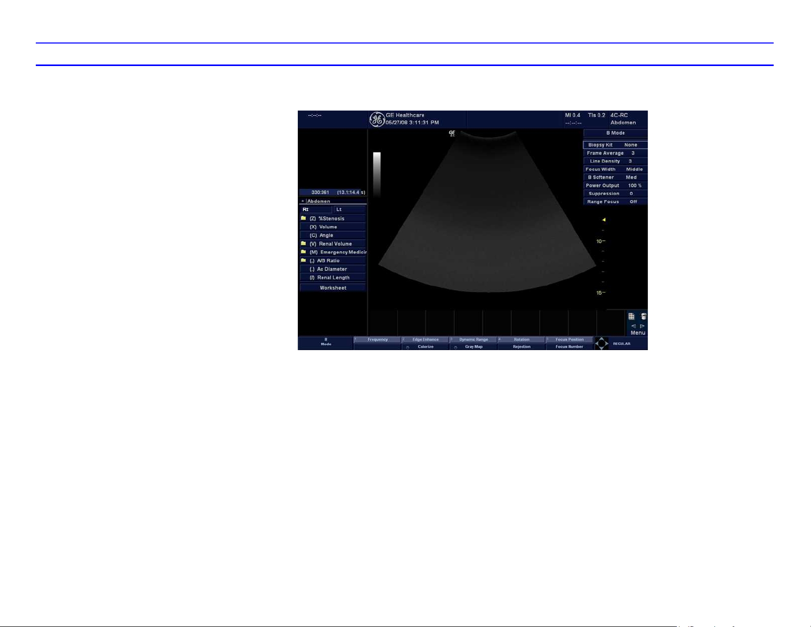
Image Optimize
B/M Mode Image Optimize
Power Output
Optimizes image quality and allows user to reduce
beam intensity. 2% increments between 0-100%.
Dynamic Range
Dynamic Range controls how echo intensities are
converted to shades of gray, thereby increasing the
adjustable range of contrast.
Focus Number and Position
Increases the number of transmit focal zones or
moves the focal zone(s) so that you can tighten up
the beam for a specific area. A graphic caret
corresponding to the focal zone position(s) appears
on the right edge of the image.
NOTE: Push key to toggle between Focus Number
and Focus Position.
NOTE: Not available when Auto frequency/Auto
depth active.
Rejection
Selects a level below which echoes will not be
amplified (an echo must have a certain minimum
amplitude before it will be processed).
Edge Enhance
Frame Average
Temporal filter that averages frames together. This
has the effect of presenting a smoother, softer
image.
Colorize
Enables gray scale image colorization. To
deactivate, reselect a Gray Map.
Gray Map
Determines how the echo intensity levels received
are presented as shades of gray.
Rotation (Up/Down)
Rotates the image by selecting the value from the
Softkey.
Frequency
Multi Frequency mode lets you downshift to the
probe's next lower frequency or shift up to a higher
frequency.
Line density
Optimizes B Mode frame rate or spatial resolution
for the best possible image.
B Mode Control Panel Controls
Auto Optimize
Automatic Tissue Optimization optimizes the image
based upon a specified Region of Interest (ROI) or
anatomy within the display.
Zoom
Magnifies a zoom region of interest, which is
magnified to approximately the size of a full-sized
image. An un-zoomed reference image is displayed
adjacent to the zoom window. The system adjusts
all imaging parameters accordingly. Press Depth/
Zoom/Ellipse key to activate Zoom. Adjust the key
to increase or decrease the zoom size. Use the
Trackball to position the Zoom ROI. Only when the
zoom size reaches the max or press the Depth/
Zoom/Ellipse key again would deactivate the
Zoom, and activate Depth.
Reverse
Flips the image left/right.
Range Focus
Improves the near/mid field image quality, borders/
interfaces, increases contrast and detail resolution
across the image, and allows for less filling in the
vessels.
Edge Enhance brings out subtle tissue differences
and boundaries by enhancing the gray scale
differences corresponding to the edges of
structures. Adjustments to M Mode's edge
enhancement affects the M Mode only.
Sweep Speed
Changes the speed at which the time line is swept.
The following speed values are available, 1, 2, 3, 4,
6, 8, 12, 16.
LOGIQ C5/C5 PRO Quick Guide Direction 5272220-100 Rev. 2 8
B/M Mode Image Optimize (continued)
B/M Mode Scanning Hints
Auto Optimize. Improves imaging performance
while reducing optimization time.
Frequency. Changes system parameters to best
optimize for a particular patient type.
Maps. There is an inter-dependency between gray
maps, gain, and dynamic range. If you change a
map, revisit gain and dynamic range settings.
Dynamic Range. Affects the amount of gray scale
information displayed. If you increase the gain, you
may want to decrease the dynamic range.
Edge Enhance. Better delineates the amount of
border crispness.
Frame Average. Smooths the image by averaging
frames. Affects the amount of speckle reduction.
Virtual Apex
On Sector probes, Virtual Apex provides a larger
field of view in the far field.
Virtual Apex is always active with sector probes.
Virtual Convex
On Linear probes, Virtual Convex provides a larger
field of view in the far field.
Virtual Convex is always active with linear probe.
Figure 10. B Mode Top/Sub Menu

LOGIQ C5/C5 PRO Quick Guide Direction 5272220-100 Rev. 2 9
Color Flow/Doppler
Image Optimize
Color Flow/Doppler Image Optimize
Baseline
Adjusts the baseline to accommodate faster or
slower blood flows to eliminate aliasing.
PRF/Wall Filter
Velocity scale determines pulse repetition
frequency. If the sample volume gate range
exceeds single gate PRF capability, the system
automatically switches to high PRF mode. Multiple
gates appear, and HPRF is indicated on the display.
Wall Filter insulates the Doppler signal from
excessive noise caused from vessel movement.
NOTE: Push button to toggle between PRF and
Wall Filter.
Angle Correct
Estimates the flow velocity in a direction at an angle
to the Doppler vector by computing the angle
between the Doppler vector and the flow to be
measured.
Quick Angle
Quickly adjust the angle by 60 degrees.
Threshold
Sample Volume Gate Length
Sizes the sample volume gate.
Map
Allows a specific color map to be selected. After a
selection has been made, the color bar displays the
resultant map.
Packet Size
Controls the number of samples gathered for a
single color flow vector.
Controls in Common with B Mode
For more information on Focal Zone, Power Output,
Frequency, Frame Average, Dynamic Range, Gray
Map, and Colorize, refer to the B/M Mode Image
Optimize section in this Quick Guide.
Scanning Hints
Line Density. Trades frame rate for sensitivity and
spatial resolution. If the frame rate is too slow,
reduce the size of the region of interest, select a
different line density setting, or reduce the packet
size.
Wall Filter. Affects low flow sensitivity versus
motion artifact.
6. Increase Frame Average.
7. Increase the Packet Size.
8. Reduce the ROI to the smallest reasonable
size.
9. Position the Focal Zones properly.
To decrease motion artifact,
1. Increase the PRF.
2. Increase the Wall Filter.
To eliminate aliasing,
1. Increase the PRF.
2. Lower the Baseline.
For venous imaging,
1. Ensure that you have selected the vascular
exam category.
2. Select a venous application.
3. Select the appropriate probe for very superficial
structure.
4. Select two focal zones.
5. Adjust the depth to the anatomy to be imaged.
6. Maintain a low gain setting for gray scale.
7. Activate Color Flow.
8. Maintain the PRF at a lower setting.
9. Increase Frame Averaging for more
persistence.
Threshold assigns the gray scale level at which
color information stops.
Doppler Display Formats
Display layout can be preset to have B-Mode and
Time-motion side-by-side or over-under.
To improve sensitivity.
1. Increase the Gain.
2. Decrease the PRF.
3. Increase the Power Output.
4. Adjust the Line Density.
5. Decrease the Wall Filter.

LOGIQ C5/C5 PRO Quick Guide Direction 5272220-100 Rev. 2 10
Figure 11. CFM Top/Sub Menu Controls
Figure 12. PWD Top/Sub Menu Controls
Color Flow/Doppler Image Optimize (continued)

LOGIQ C5/C5 PRO Quick Guide Direction 5272220-100 Rev. 2 11
Basic Measurements/
Calculations
Basic Measurements
NOTE: The following instructions assume that you
first scan the patient and then press Freeze.
B Mode
Distance and Tissue Depth Measurements
1. Press Measure once; an active caliper
displays.
2. To position the active caliper at the start point
(distance) or the most anterior point (tissue
depth), move the Trackball.
3. To fix the start point, press Set. The system
fixes the first caliper and displays a second
active caliper.
4. To position the second active caliper at the end
point (distance) or the most posterior point
(tissue depth), move the Trackball.
5. To complete the measurement, press Set. The
system displays the distance or tissue depth
value in the measurement results window.
NOTE: Before you complete a measurement:
To toggle between active calipers, press
Measure.
To erase the second caliper and the current
data measured and start the measurement
again, press Clear once.
NOTE: After you complete the measurement, to
erase all data that has been measured to this point,
but not data entered onto worksheets, press Clear.
Circumference/Area (Ellipse) Measurement
1. Press Measure once; an active caliper
displays.
2. To position the active caliper, move the
Trackball.
3. To fix the start point, press Set. The system
fixes the first caliper and displays a second
active caliper.
4. To position the second caliper, move the
Trackball.
5. Adjust the Ellipse control; an ellipse with an
initial circle shape appears.
6. To position the ellipse and to size the measured
axes (move the calipers), move the Trackball.
7. To increase the size, adjust the Ellipse control
in a clockwise direction. To decrease the size,
adjust the Ellipse control in a counterclockwise
direction.
8. To toggle between active calipers, press
Measure.
9. To complete the measurement, press Set. The
system displays the circumference and area in
the measurement results window.
NOTE: Before you complete a measurement:
To erase the ellipse and the current data
measured, press Clear once. The original
caliper is displayed to restart the
measurement.
To exit the measurement function without
completing the measurement, press Clear
a second time.
Circumference/Area (Trace) Measurement
1. Press Measure twice; a trace caliper displays.
2. To position the trace caliper at the start point,
move the Trackball.
3. To fix the trace start point, press Set. The trace
caliper changes to an active caliper.
4. To trace the measurement area, move the
Trackball around the anatomy. A dotted line
shows the traced area.
NOTE: To erase the dotted line but not the trace
caliper, press Clear once. To clear the trace caliper
and the current data measured, press Clear twice.
NOTE: To erase the line (bit by bit) back from its
current point, move the Trackball or adjust the
Ellipse control.
5. To complete the measurement, press Set. The
system displays the circumference and the area
in the measurement results window.
NOTE: Before you complete a measurement:
To erase the line (bit by bit) back from its
current point, move the Trackball or adjust
the Ellipse control counterclockwise.
To erase the dotted line but not the trace
caliper, press Clear once.
To clear the trace caliper and the current
data measured, press Clear twice.

LOGIQ C5/C5 PRO Quick Guide Direction 5272220-100 Rev. 2 12
Volum e
1. To make a volume calculation, do one of the
following:
• Make one distance measurement.
• Make two distance measurements.
• Make three distance measurements.
NOTE: The three distance measurements
should be done in the dual format mode (side
by side images). One measurement is usually
made in the sagittal plane and two
measurements in the axial plane. To use the
dual format mode, press the L or R key on front
panel.
• Make one distance and one ellipse
measurement.
• Make one ellipse measurement.
2. Select Volume.
M/PWD
Time Interval Measurement
1. Press Measure twice; an active caliper with a
vertical dotted line displays.
2. To position the active caliper at the start point,
move the Trackball.
3. To fix the start point, press Set. The system
fixes the first caliper and displays a second
active caliper.
4. To position the second caliper at the end point,
move the Trackball.
5. To complete the measurement, press Set. The
system displays the time interval between the
two calipers in the measurement results
window.
Velocity Measurement
1. Press Measure; an active caliper with a vertical
dotted line displays.
2. To position the caliper at the desired
measurement point, move the Trackball.
3. To complete the measurement, press Set. The
system displays the velocity measurement in
the measurement results window.
PI, RI, S/D Ratio, D/S Ratio or A/B Ratio
Select PI, RI, S/D Ratio, A/B Ratio or D/S Ratio
from the Doppler Primary and secondary menu.
Perform velocity measurements.
1. The first caliper is the start point on the Doppler
waveform. This would be V
velocity for RI, systole for S/D ratio, "A" velocity
for A/B ratio or diastole for D/S ratio.
2. The second caliper is the end-point caliper to
the end point of the Doppler waveform. This
would be V
diastole for S/D ratio, "B" velocity for A/B ratio
or systole for D/S ratio.
NOTE: For the PI calculation, if Auto Trace is not
selected, manually trace the waveform between
V
and Vd.
MAX
NOTE: For the PI calculation, if Auto Trace is on,
the system automatically traces the waveform when
Set is pressed to fix V
for PI, minimum velocity for RI,
d
.
d
for PI, peak
MAX
Worksheets
Measurement/Calculation worksheets are available
to display and edit measurements and calculations.
There are generic worksheets as well as
Application specific worksheets. The worksheets
are selected from the Measurement menu or by
pressing the function key defined on keyboard.
LOGIQ C5/C5 PRO Quick Guide Direction 5272220-100 Rev. 2 13
Using Probes
CAUTION
Using Probes
Connecting a probe
1. Place the probe's carrying case on a stable
surface and open the case.
2. Carefully remove the probe and unwrap the
probe cable.
3. DO NOT allow the probe head to hang free.
Impact to the probe head could result in
irreparable damage.
Inspect the probe before and after each use for
damage or degradation to the housing, strain
relief, lens, seal and connector. DO NOT use a
transducer which appears damaged until
functional and safe performance is verified. A
thorough inspection should be conducted
during the cleaning process.
4. Align the connector with the probe port and
carefully push into place with the cable facing
the front of the system.
5. Turn the connector locking lever up.
6. Carefully position the probe cord so it is free to
move, but not resting on the floor.
Activating the probe
Swich the probe
Swich probe between the two probe through
pressing Probe bottom.
NOTE: Swiching the probe frequently will cause
probe can not be supported warning message.
Deactivating the probe
When deactivating the probe, the probe is
automatically placed in standby mode.
1. Ensure the LOGIQ C5/C5 PRO is in freeze
mode. If necessary, press the Freeze key.
2. Gently wipe the excess gel from the face of the
probe.
3. Carefully slide the probe around the right side
of the keyboard, toward the probe holder.
Ensure that the probe is placed gently in the
probe holder.
Disconnecting the probe
Probes can be disconnected at any time. However,
the probe should not be active when disconnecting
the probe.
1. Move the probe locking handle counterclockwise.
2. Pull the probe and connector straight out of the
probe port.
3. Carefully slide the probe and connector away
from the probe port and around the right side of the
keyboard.
4. Ensure the cable is free.
5. Be sure that the probe head is clean before placing the probe in its storage box or a wall hanging
unit.
Fault conditions can result in electric shock hazard.
Do not touch the surface of probe connectors which
are exposed when the probe is removed. Do not
touch the patient when connecting or disconnecting
a probe.
The probe activates automatically in the currentlyselected operating mode when it is connected. The
probe's default settings for the mode and selected
exam are used automatically.
LOGIQ C5/C5 PRO Quick Guide Direction 5272220-100 Rev. 2 14
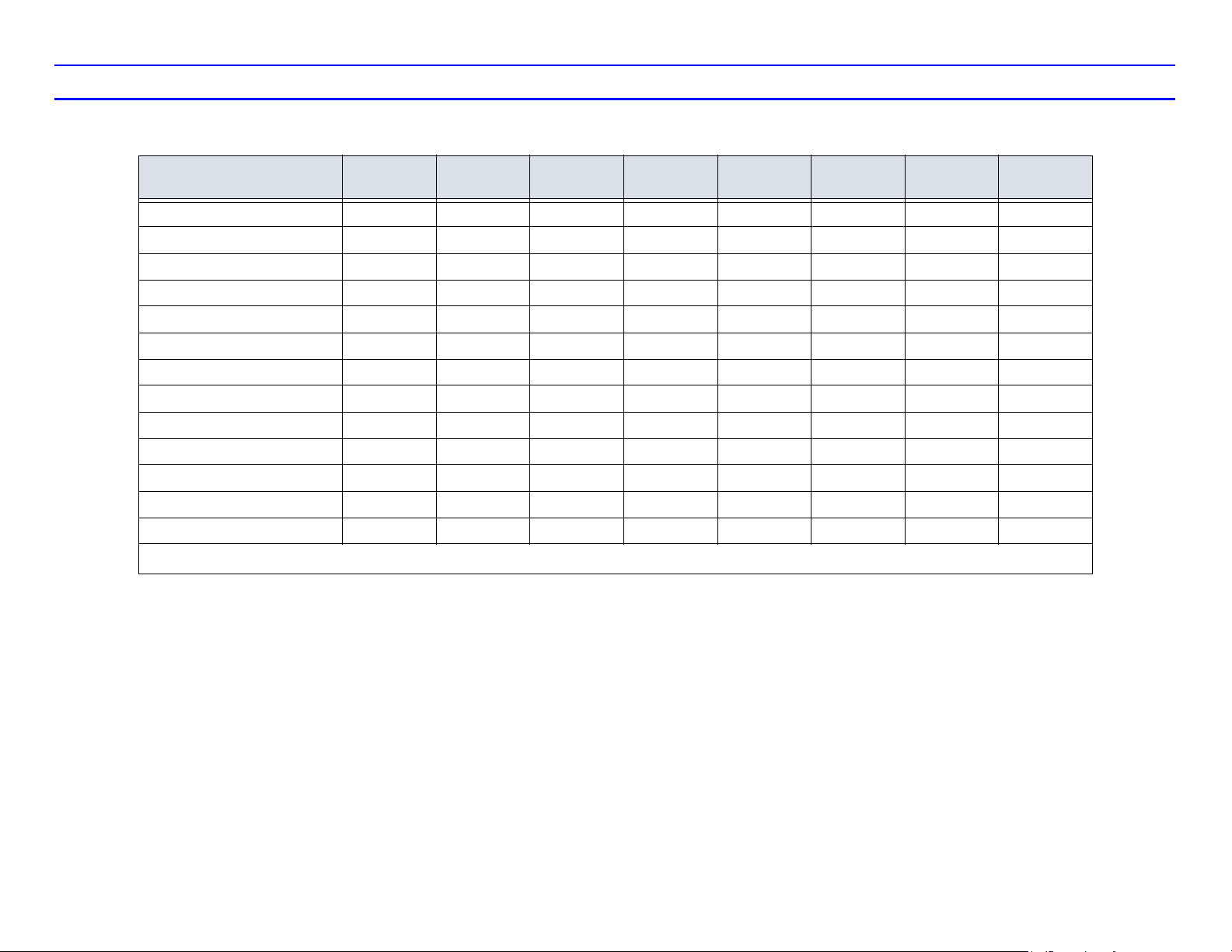
Probe Application
Table 1: Probe Indications for Use
Probe Application E7C-RC E6C-RS 6.5C--RS 4C-RS 3.8C-RC 7.5L-RC 7L-RC 3S-RC
Abdomen 0 X X 0
Small Parts X X X X
Obstetrics X X X X
Gynecology X X X
Pediatrics X X X 0 0
Neonatal 0 0 0
Urology XX
Cardiac X X X
Endocavity
Transcranial 0 X
Intraoperative 0 0 0
Vascular 0 0 0 X X
Biopsy X XXXXXX
X Main Application O Accessory Application
Loading...