


PDW22SCRARSS
GE PDW22SCRARSS, PDS22SHRBRSS, PDS22SHRBLSS, PDS22SHRARSS, PDS22SHRALSS Owner’s Manual
...
wvvvv.GEAppliances.com
Safety In_Ttrudions ........... 2-4
bq
©
Operating Instruc_tions
Additional Features ............. 9
Automatic Icemaker . .......... 19
Controls .................... 5, 6
Crispers and Pans ............. 10
Freezer ...................... 11
Shelves and Bins ............. 8, 9
_'ater Filter ................... 7
Care and Cleaning ........ 13-15
Installation Instructions
Installing the Refligerator . . . .17-91
Installing the _4'ater Line ..... 30-32
Preparing to Install
the Refligerator . .............. 16
Removing and Replacing the
Freezer Drawer ............ 22, 23
Reversing the Door Swing .... 24-29
Troubleshooting Tips ....... 33-36
Normal Operating Sounds ...... 33
Models20 and22
Cong_lateur inf>rieur
R frig&ateurs
La section fran_aise commence a la page 43
Congelador inferior
Refrigeradores
La secci6n en espafol empieza enla pagina83
Consumer Support
Consumer Support ..... Back (',over
Performance Data Sheet ........ 41
Product Registration ........ 37, 38
_'arranty for Canadian
Customers ................... 39
_'arrantv for U.S. Customers ..... 40
Write the model and serial
numbers here:
Model #
Serial #
Find these numbex_ on a label
on the right side, near the top of
the refl'igerator compartment.
3828JLSO12B 197D#618PO03 49-60323 02-04Jfl
IMPORTANTSAFETYINFORMATION.
READALLINSTRUCTIONSBEFOREUSING.
A WARNING!
Use this appliance only for its intended purpose as described in this Owner's Manual
SAFETYPRECAUTIONS
When using electrical appliances, basic safety precautions should be foflowed, including the following:
This refiigerator must be properly installed
and located in accordance with the Installation
Instructions before it is used.
Do not allow children to climb, stand or hang
on the shelves in the refl-igerato_: They could
damage the refl-igerator and seriously iqjure
themselves.
Do not touch the cold surfi_ces in the fl'eezer
compartment when hands are damp or wet.
Skin may stick to these extremely cold sml'i_ces.
, Do not store or use gasoline or other flammable
wq)()_s and liquids in the vicinity of this or anv
other appliance.
Keep finge_ out of the "pinch point" areas;
clearances between the doo_s and between
the (loo_s and cabinet are necessarily small.
Be carefld closing (loo_s when children are
in the area.
In refl-igerato_s Mth automatic icemake_s,
avoid contact with the moving parts ot the
ejector mechanism, or with the heating element
that releases the cubes. Do not place finge_s or
hands on the automatic icemaking mechanism
while the refi-igerator is plugged in.
Unplug the reli-igerator befi)re cleaning and
making repai_.
NOTE: Westronglyrecommendthat any servicingbe
performedby a quafified individual.
Setting either or both controls to 0 (Off)does
not remove power t() the light circuit.
Do not reli'eeze ti'()zen fi)ods which have
thawed completely.
2
DANGER!RISKOFCHILDENTRAPMENT
PROPERDISPOSALOFTHEREFRIGERATOR
GEAppliances.com
Child entrapment and suffocation are not i)rol)lems
of the past.Junked or abandoned refl_igerato_ are
still dangerous...even if they will sit for "just a few
days." If you are getting rid of your old refrigerator,
please follow the instructions below to help prevent
accidents.
Before YouThrowAway YourOldRefrigerator
Refrigerants
All refrigeration i)ro(hwts contain refl'igerants,
which tinder fe(leral law Inust be rellloved prior
to l)roduct disposal. If wm are getting rid of an
old refl'igeration product, check with the
company handling the disposal about what
to do.
or Freezer:
Take off the do ots.
i,eave the shelxes in place so that children max
not easily climb inside.
USEOFEXTENSIONCORDS
Because of potential safety hazards under certain conditions, we strongly recommend against
the use of an extension cord.
However; if xou must use an extension cord, it is absolt/tel_ necessar_ that it be a UI,-listed (in the United
States) or a CSA certified (in Canada),. -wire ,gr°unding, tX,'l)e appliance extension cord having, a ,gr°unding,
D'pe I)lu°_ and outlet and that the electrical rating, of the cord be 15 amperes (minimum) and 120 xolts.
IMPORTANTSAFETYINFORMATION.
READALLINSTRUCTIONSBEFOREUSING.
WARNING!
HOWTOCONNECTELECTRICITY
Do not, under any circumstances, cut or remove the third (ground) prong from the power cord.
For personal safety this appliance must be properly grounded.
The power cord of this appliance is equipped
with a &prong (grounding) plug which mates
with a standard 3-prong (grounding) wall outlet to
minimize the possibili F of electric shock hazard
fl'om this appliance.
Have the wall outlet and circuit checked by a
qualified electridan to make sure the outlet is
properly grounded.
Where a standard 2-prong wall outlet is
encountered, it is your personal responsibili_' and
obligation to have it replaced with a properly
grounded 3-prong wall outlet.
The refl-igerator should always be plugged into its
own individual electrical outlet which has a w)ltage
rating that matches the rating plate.
This provides the best pe_fommnce and also
I)rexents oxerloading, house wiring circuits which
could cause a fire hazard fl'om oxerheated wires.
Never unplug your refl_igerator by pulling on the
power cord. Mways gill ) plug firefly and pull
straight out fl'om the outlet.
Repair or replace immediately all power cords that
have become fl'aved or otherwise damaged. Do not
use a cord that shows cracks or abrasion damage
along its length or at either end.
When moving the refi_igerator away from the
wall, be carefld not to roll over or damage the
power cord.
USEOFADAPTERPLUGS(AdapterplugsnotpermittedinCa_adaJ
Because of potential safety hazards under certain conditions, we strongly recommend against
the use of an adapter plug.
Howe\'et; if you must use an adapter; where local
codes i)emfit, a temporary connection may be made
to a properly grounded 2-prong wall outlet by use
of a UIAisted adaptor a\:filable at most local
hardwai'e stoi'es.
The linger slot in the adapter must be aligned with
the larger slot in the _;fll outlet to provide proper
polarity in the connection of the power cord.
When disconnecting the power cord fl'om the
a(lapte_; always hold the adapter in place with one
hand while pulling the power cord I)lug with the
other hand. If this is not done, the adapter ground
temfinal is very likely to break with repeated use.
If the adapter ground temfinal brea!cs, DO NOT USE
the refrigerator until a proper ground has been
established.
Attaching the adapter ground termlhal to a wall outlet
cover screw does not ground the appliance unless the
cover screw is metal, and not insulated, and the waft
outlet is grounded through the house wiring. Youshould
have the ckcuit checkedby a qualified electrician to make
sure theoutlet is proper/)/grounde_
READANDFOLLOWTHISSAFETYINFORMATIONCAREFULLY.
SAVETHESEINSTRUCTIONS
4
Aboutthe controlswith
temperaturesettings.(for othermodels, see nextpage) GEAppl_nce_com
t
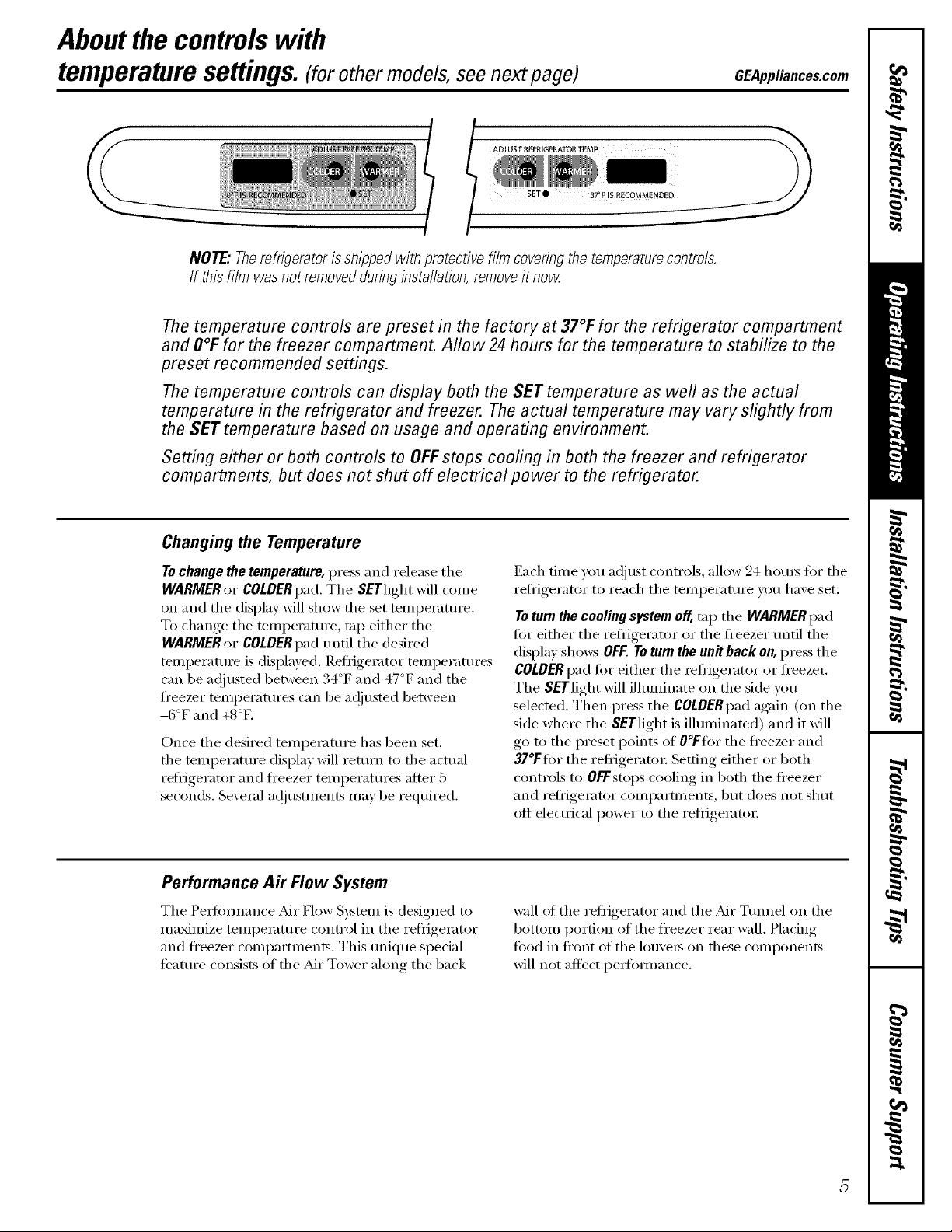
NOTE,"Therefrigeratoris shippedwith protectivefilm coveringthe temperaturecontrols.
If this film was notremovedduringinstallation,removeit now
Thetemperature controls are preset in the factory at 37°1:for the refrigerator compartment
and #OFfor the freezer compartment. Allow 24 hours for the temperature to stabilize to the
preset recommended settings.
Thetemperature controls can display both the SET temperature as well as the actual
temperature in the refrigerator and freezer. The actual temperature may vary slightly from
the SET temperature based on usage and operating environment.
Setting either or both controls to OFFstops cooling in both the freezer and refrigerator
compartments, but does not shut off electrical power to the refrigerator.
Changingthe Temperature
To change the temperature, press and release the
WARMER or COLDER pad. The SETlight will c(:,me
on and the display will show the set temperature.
To change the teml)eratm'e, tn l) either the
WARMER or COLDER pad until the desired
teilll)erattlre is displayed, Refl'igerator teml)erattlres
can be a(!iusted between 34°F and 47°F and the
fl'eezer teInI)eratures can be ac!iusted between
-6°F and +8°E
Once the desired temperature has been set,
the temperatm'e display will return to the actual
refi'igei'ator and fl'eezer teml)erattlres afiei" 5
seconds, Several ac!iustments may be required,
Performance A# Flow System
The Pedbm_an('e _Mr Flow System is designed to
maMmize temperature control in the refl_igerator
and fl'eezer conq)artmei_ts. This tmique special
teatm'e consists of the _dr Tower along the back
Each time you a(!just controls, allow 24 horns fiw the
refl_igerator to reach the temperatm'e you have set.
Toturn the cooling system off, tnI) the WARMER pad
fro" either the refl_igerator or the fl'eezer until the
display shows OFF.To turn the unit back on, press the
COLDERpad fl)r either the refl_igerator or fl'eezei;
The SErlight will illuminate on the side you
selected. Then press the COLDERpad again (on the
side where the SETlight is illuminated) and it will
go to the preset points of O°Fflw the fi'eezer and
37°Ffi)r the refl-igeratm; Setting either or both
controls to OFFstops cooling in both the fi'eezer
and refi-igerator compartments, but does not shut
off electrical power to the refl_igeratm;
wall of the refrigerator and the _Mr Tmmel on the
bottom portion of the fl'eezer rear wall. Placing
fi)od in fl'ont of the lou\'e_s on fl_ese components
will not affect i)eHbm_ance.
Aboutthe controlswith numberedsettings.
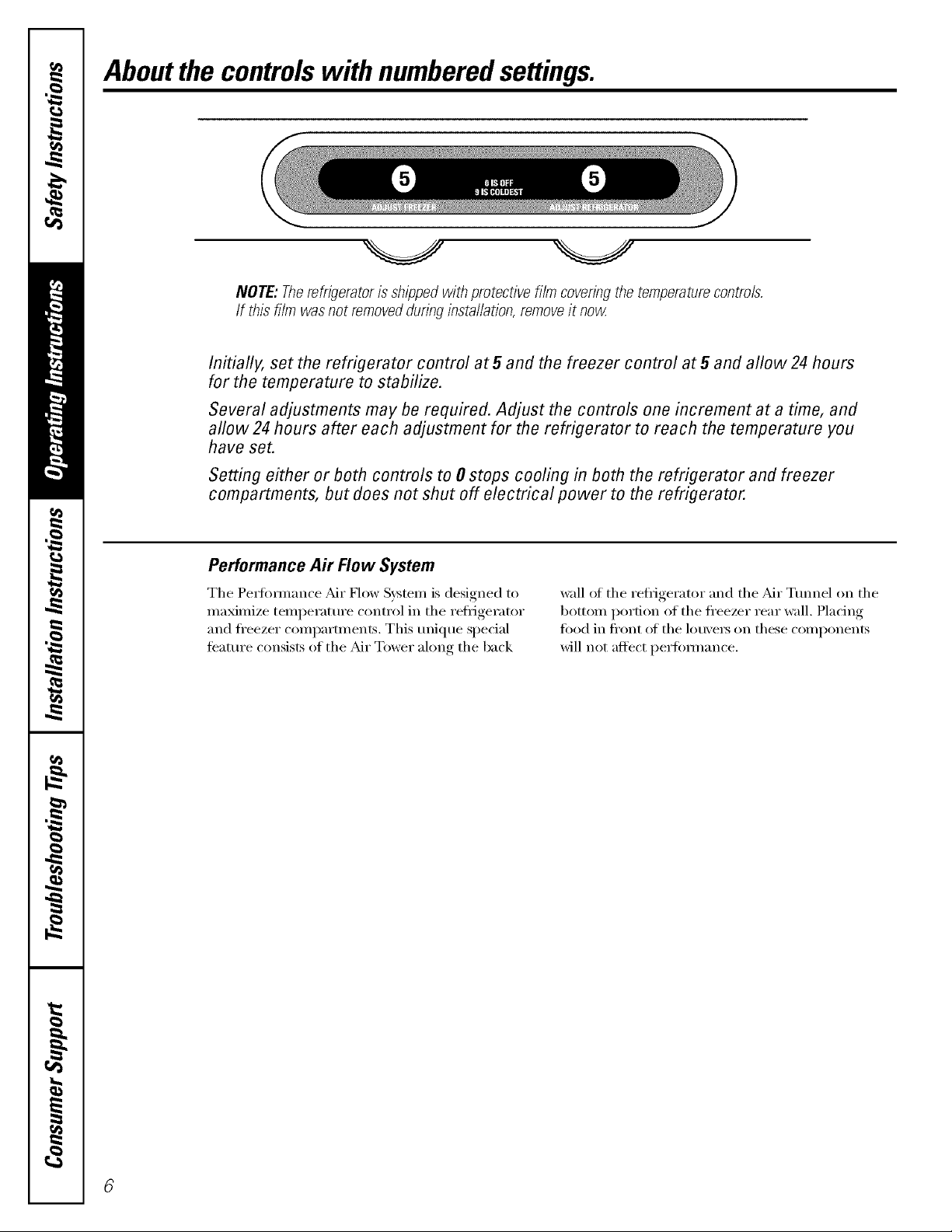
NOTE: Therefrigeratoris shippedwith protectivefilm coveringthe temperaturecontrols.
If this film was not removedduringinstallation,removeit now
Initially, set the refrigerator control at5 and the freezer control at5 and allow24 hours
for the temperature to stabilize.
Several adjustments may be required. Adjust the controls one increment at a time, and
allow24 hours after each adjustment for the refrigerator to reach the temperature you
have set.
Setting either or both controls to 0 stops cooling in both the refrigerator and freezer
compartments, but does not shut off electrical power to the refrigerator.
Performance Air Flow System
The Pe_tmmance _Mr Flow System is designed to
maximize temperattu'e control in the refl_igerator
and fl'eezer compamnents, This tmique special
teatm'e consists of the _dr Tower along the back
wall ot the refligerator and the _dr Tmmel on the
bottom portion of the fl'eezer rear wall. Placing
fi)od in fl'ont of the lou\'e_ on these components
will not affect perfi)m_ance.
Aboutthe water filter.(onsomemodels) GEAppliances.com
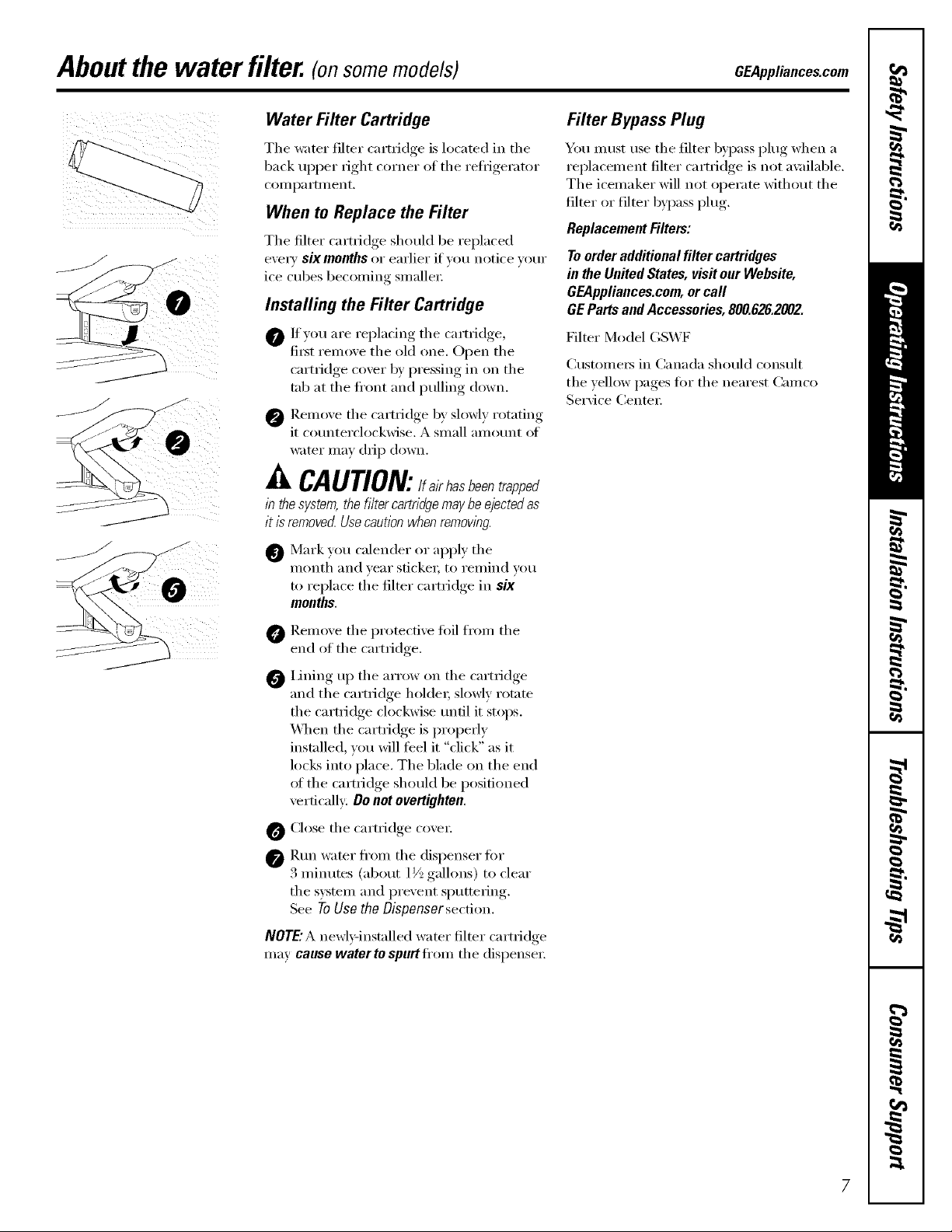
Water Filter Cartridge
The water filter cartridge is located in the
back upper right corner of the reflJgerator
COIllI)a i'tlilent,
When to Replace the Filter
The filter cartridge should be replaced
evex T six months or earlier if wm notice w)ur
ice cubes becoming smaller:
Filter Bypass Plug
You must use the filter 1upass plug when a
replacement filter cartridge is not a\_filable.
The icemaker will not operate without the
filter or filter byl)ass plug.
Replacement Filters:
To order additional filter cartridges
in the United States, visit our Webs#e,
GEAppliances.com,or call
Installing the Filter Cartridge
0 Ifyou are replacing the cartridge,
fi_t remove the old one. Open the
J
J
cartridge cover by pressing in on the
tab at the fl'ont and pulling down.
@ Remove the cartridge by slowly rotating
it cotmterclockwise. A small amount ot
water may drip down.
GE Parts and Accessories, 800.626.2002.
Filter Model GS'WF
Customer5 in Canada should consult
tile yellow pages t0r the nearest Camco
Service Center:
CAUTION:/f , h sbeen
in thesystem,the filtercartridgemaybeejectedas
it isremovedUsecautionwhenremoving.
Mark you calender or apply the
month and year socket; to remind w)u
to replace the filter cartridge in six
months.
O Remoxe the protective fi)il from the
end of the cartridge.
Lining up the arrow on tile cartridge
and the cartridge holdeL slowly rotate
the cartridge clockwise tmtil it stops.
\_]_en the cartridge is properly
installed, you will feel it "click" as it
locks into place. The blade on the end
ot the cartridge should be positioned
vertically: Do not overtighten.
O Close the cartridge cove_;
O Rtm water fl'om the dispenser for
3 minutes (about 1V_,gallons) to clear
tile system and prevent sputtering.
See ToUsethe Oispensersection.
NOTE:Anewly-installed water filter cartridge
may cause water to spurt ti'om the dispense_:
7

Aboutthe shelvesandbins.
Not all features are on all models.
Rearranging the Shelves
Shel;es in the refrigerator cOn_l)artment are a(!iustable.
Refrigerator Compartment
Toremove:
o 0
0 Tilt the shelf up at the fl'ont.
0 I,ifl the shelf ul) at the back and
bring the shelf ()tit.
Somemodelshavewireshelvesthat
canbeadjustedinthesamemam?e_
Toreplace:
0 _'_hile tilting the shelf up, insert the top
hook at the back of the shelf in a slot
(m the track.
0 I,ower the fl'ont of the shelf until the
bottom of the shelf locks into place.
i 0
Spillproof Shelves (onsomemodels)
Spillproof shelves have special edges to
hel I) prevent spills fl'om dripping to lower
shelves. To relnove or rel)la('e the shelves,
see Rearranging the Shelves,
Slide-Out Spillproof Shelf (onsomemodels)
The slide-out spillproof shelf allows you
to reach items stored behind otheis. The
spedal edges are designed to hel I) prevent
spills from dripping to lower shelves.
Toremove:
0 Reinove all items from shell
0 Slide the shelf ()tit until it stops.
Lift the fl'ont edge of the shelf until the
central tabs are above the fl'ont bin:
0 Continue pulling the shelf fi)rward
until it can be removed.
Toreplace:
0 Place the rear shelf tabs just in fl'ont of
the central notches on the shelf fl'ame,
Slide the shelf in un61 the central tabs
are slightly behind the fl'ont bar.
0 i,ower the shelf into place until it is
horizontal and slide the shelf in.
Make surethat the shelf sitsflat after reinstallation
anddoesn't move freely fromside to side.
Make sureyoupush the shelvesall the wayin
before youclose the door
8
GEAppliances.com
Fingerhold
mgger
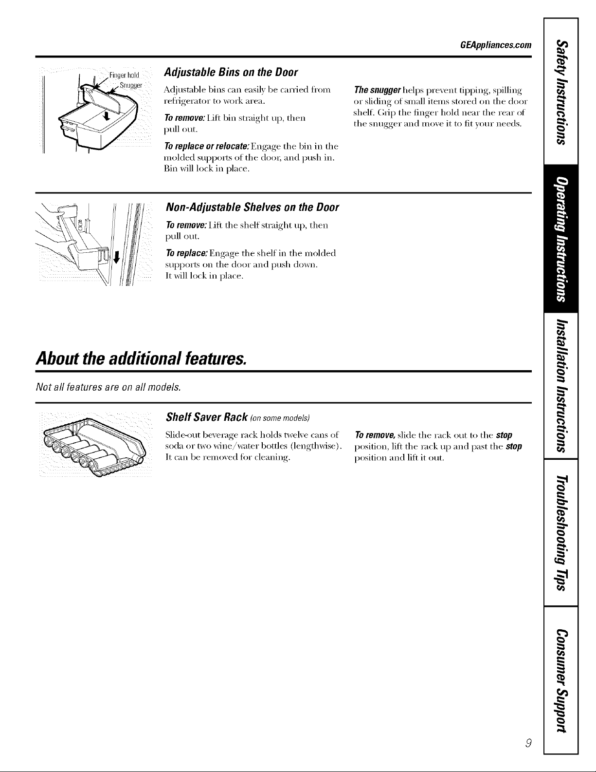
Adjustable Bins on the Door
A(!justable bins can easily be carried flx,m
reflJgerator to work area.
Toremove: IJfl bin straight up, then
pull out.
Toreplace or relocate: Engage the bin in the
molded supports (ff the dora; and push in.
Bin will lock in place.
' Non-Adjustable Shelves on the Door
Toremove: Lift the shelf straight up, then
pull out.
Toreplace: Engage the shelf in the molded
supports on the door and push down.
It will lock in place.
The snugger helps prevent tipping, spilling
or sliding of small items stored on the door
shelf. (;_ip the finger hold near the rear of
the snugger and move it to fit yore" needs.
Aboutthe additional features.
Not all features are on all models.
Shelf Saver Rack (onsomemodels)
Slide-out beverage rack holds twelve cans of
soda or two wine/wamr bottles (lengthwise).
It can be removed fi)r cleaning.
Toremove, slide the rack out to the stop
position, lift the rack up and past the stop
position and lift it out.
Aboutthe crispersandpans.
Not all features are on all models.
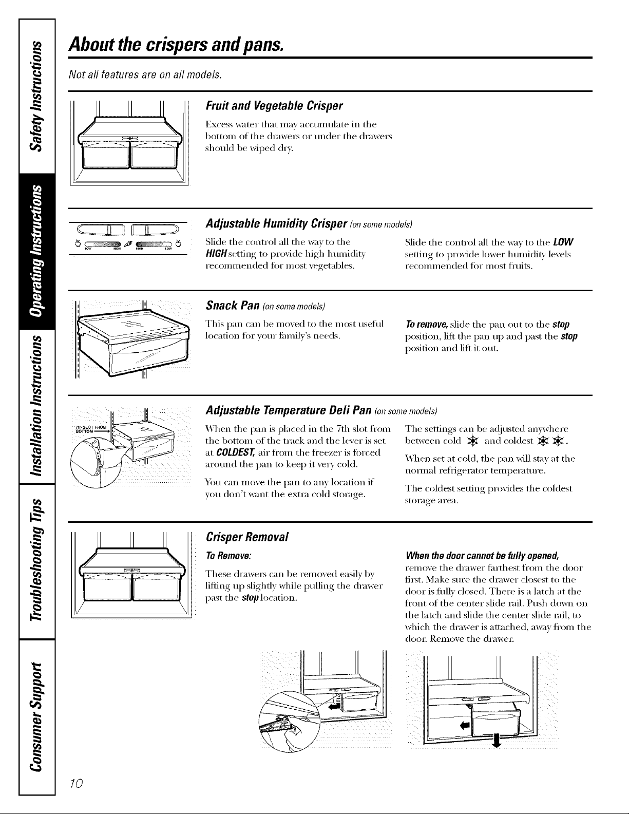
Fruit and Vegetable Crisper
Excess water that ma_ accunmlate in the
bottom of the (h'aweI_ or under the (h'awei_
should be wiped dry.
Adjustable Humidity Crisper (onsomemodels)
Slide the control all the way to the Slide the control all the wax to the LOW
HIGHsetting to proxide high humidit_ .settin,,_ to proxide lower humidity, lexels
recommended fi)r most xegetables, recommended fi)r most fl'uits.
Snack Pan (on some models)
This pan can be mo_ed to the most useflfl
location fin" )ore" fmnil)'s needs.
To remove, slide the pan out to the stop
position, lilt the pan u l) and past the stop
position and lift it out.
Adjustable Temperature Dell Pan (onsomemodels)
When the pan is placed in the 7th slot fl'om
the bottom of the track and the lever is set
at COLDEST, air fl'om the fl'eezer is torced
around the pan to kee I) it very cold.
You can move the pan to any location if
you don't want the extra cold storage.
The settings can be a(!justed anywhere
1)et_ven cold _ and coldest _ _.
X4]_en set at cold, the pan will stay at the
nom_al refligerator temperatm'e.
The coldest setting provides the coldest
storage area.
Crisper Removal
ToRemove:
These (h'awei_ can be removed easily 1)v
lifting up slightl)while pulling the drawer
past the stop location.
When the door cannot be fully opened,
rein(_x'e the drawer fi_rth est froln the door
filst. Make sure the drawer closest to the
door is fifllv closed. There is a latch at the
fl'ont of the center slide rail. Push down on
the latch and slide the center slide rail, to
which the drawer is attached, a_)' fl'om the
dora: I{eInove fl_e drawer
10
Aboutthe freezer. GEAppliances.com
Not all features are on all models.
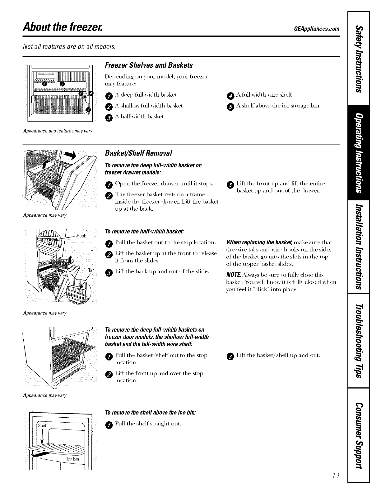
Freezer Shelves and Baskets
Depending on your model, your fi'eezer
Ill[ly feattlI'e:
Appearance and features may vary
Appearance may vary
Hook
O A deep fllll-width basket
A shallow fllll-width basket
O A half:width basket
Basket/Sheff Removal
Toremove the deep full-width basket on
freezer drawer models:
0 Open tile freezer drawer until it stops.
@ Tile fl'eezer basket rests on a fl'anle
inside tile fl'eezer (h'awe_; i,ift tile basket
up at tile back.
Toremove the half-width basket:
0 Pull tile basket out to tile stop location.
@IJtt tile basket up at tile ti'ont to release
it from the slides.
Lift the back up and out of the slide.
A flfll-width wire shelf
A shelf aboxe tile ice storage bin
0 Lilt tile fl'ont up and lilt tile entire
basket up and out of tile (h'awe_:
When replacing the basket make sure that
tile Mre tabs and wire l/oo]_; on tile sides
of tile basket go into tile slots in tile top
of the upper basket slides.
NOTE:Mw'avsbe sure to fiflly close this
basket. You will know it is fifllv closed when
w)u teel it "click" into place.
Appearance may vary
Appearance may vary
Toremove the deep full-width baskets on
freezer door models, theshallow full-width
basket and the full-width wire shelf."
Pull tile basket/shelf out to tile stop
location.
IJfl tile fl'ont up and oxer tile stop
location.
Toremove the shelf above the ice bin:
Pull tile shelf straight out.
Lift tile basket/shelf up and out.
11
Aboutthe automaticicemaker.
A newly installed refrigerator may take 12 to 24 hours to begin making ice.
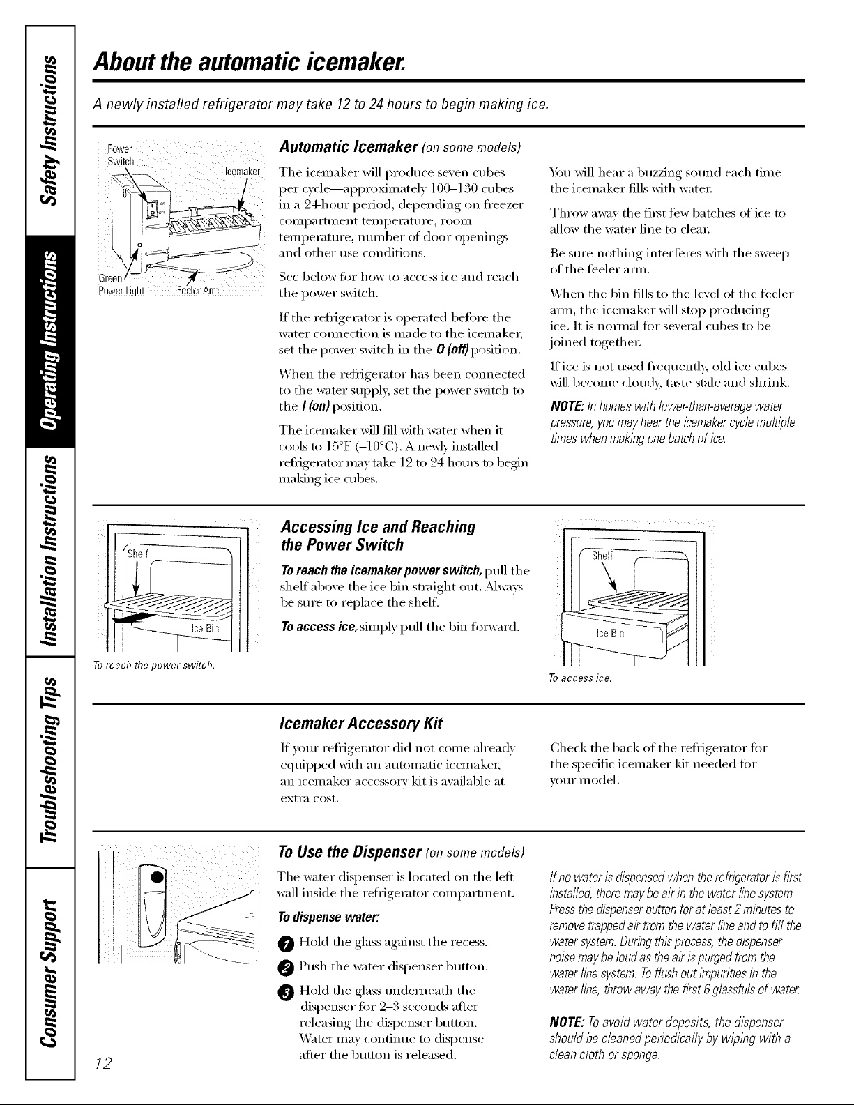
Power Automatic lcemaker (onsomemodels)
Switch
The icemaker will produce seven cubes
per c) cle>--ai)i)roxinmtel ) ] 00-1 bO cubes
in a 24-hour period, depending on fl'eezer
COilli)artlllent teillpei'att/i'e, i'OOill
teml)eratm'e, nmnber of door openings
and other use conditions.
See below fi)r how to access ice and reach
the power switch.
If the refl_igerator is operated befiwe the
water connection is made to the icemakeL
set the power switch in the 0 (o#) position.
When the reflJgerator has been connected
to the water SUl)ply, set the power switch to
the I (On)position.
The icemaker will fill with water when it
cools to 15°F (-10°C). A newly installed
refi_igemtor may take 12 to 24 hems to beg_n
making ice cubes.
You Mll hear a buzzing sotmd each time
the icemaker fills with water;
Throw away the first tew batches of ice to
allow the water line to clea_:
Be sm'e nothing interteres with the sweep
of the teeler am/.
_._]_en the bin fills to the level {ff the teeler
am_, the icemaker will stop producing
ice. It is nomml for several cubes to be
joined together:
If ice is not used flequenfl> old ice cubes
will become cloud}; taste stale and shrink.
NOTE: Inhomes with lower-than-averagewater
pressure,you mayhear theicemakercyclemultiple
times whenmaking onebatchof ice.
ToreachflTepower switch.
)!ii iiiiiiiii iiii i!
12
Accessing Ice and Reaching
the Power Switch
Toreach the icemaker power switch, pull the
shelf above the ice bin straight out. Mwa):s
be sm'e to replace the shelf.
Toaccess ice, simply pull the bin fiwward.
Icemaker Accessory Kit
If )our refiigerator did not come ah'ea&
equipped with an automatic icemakex;
an icemaker accessory kit is axailable at
extra cost.
To Use the Dispenser (onsomemodels)
The water dispenser is located on the left
wall inside the refl_igerator compartment.
Todispense water:
Hold the glass against the recess.
@ Push the water dispenser button.
O Hold the glass tmderneath the
dispenser for 2-3 seconds after
releasing the dispenser button.
Water may continue to dispense
after the button is released.
To access ice,
Check the back of the refrigerator fiw
the specific icemaker kit needed fi)r
VOIII" model,
If nowateris dispensedwhentherefwemtorisfirst
installed,theremaybeairin thewaterlinesystem.
Pressthedispenserbuttonforat/east2minutesto
removetrappedair fromthewaterfineandtoill/the
watersystem.Duringthisprocess,thedispenser
noisemaybeloudastheairispurgedfromthe
waterlinesystem.Toflushouti_npuritiesin the
waterline,throwawaythefirst6glassfulsofwater
NOTE:Toavoidwaterdeposits,thedispenser
shouldbecleanedpenodicallybywipingwith a
cleancloth orsponge.
Careand cleaning ofthe refrigerator. GEAppliances.com
Cleaning the Outside
The doorhandles and trim. Clean with a cloth
daml)ened with soapy water: Dry with a sott
cloth. Do not use wax on the door handles
and trim.
Keep the outside clean. _A]l)e Mth a clean
cloth lightly dampened Mth kitchen
appliance wax or mild liqlfid dish
detergent. D_3' and polish with a clean,
soft cloth.
Do not wipe the refngerator with a soiled dish
cloth or wet towel Thesemay leave a residue
that can erode the pa/n_ Do not usescouring
pads,powdered cleaners, bleach or cleaners
contein/ng bleach because these products can
scratch and weaken the paint finish.
Cleaning the Inside
The stainless steel panels and doorhandles.
Stainless steel (on some models) can be
cleaned with a commerdallv available
stainless steel cleanex: A spray-on stainless
steel cleaner works best.
Do not use appliance wax or polish
on the stainless steel,
Tohelp prevent odors, leave an open be× _:,t
baking soda in the reflJgerator and fi'eezer
COIIII)_I I'[ll/ents.
Unplug the refrigerator before cleaning. If this
is not practical, wring excess moisture ()tit
of sponge or cloth when cleaning arotmd
switches, lights or controls.
Lrse an appliance wax polish on the inside
sml'hce between the do(n_.
Use warn/ water and baking soda solution--
about a tnblesl)oon (15 ml) of baking soda
to a quart (l liter) oI water: This both cleans
and neutralizes odo_. Rinse and wipe (h_'.
_Mter cleaning the door gaskets, apply a
thin laver of petrolemnjelly to the door
gaskets at the hinge side. This helps kee I)
the gaskets ti'om sticking and bending out
of shape.
Avoid cleaning cold glass shelves with hot water
because the extreme temperature difference may
cause them to break. Handleglass shelves
carefull_z Bumping tempered g/ass can cause
it to shatter
Donot washanyplasticrefrigeratorpartsin
thedishwasher
/3
Careand cleaning of the refrigerator.
Behind the Refrigerator
Be caretul when moving the refl_igerator
away fl'om the wall. M1 types of floor
coverings can be (lamaged, particularly
cushioned coverings and those with
embossed stiFf,ices.
Pull the retiigerator straight out and return
it m position by pushing it straight in.
Moving the refligerator in a side direction
may result in damage to the floor covering
or reffigeratoi:
Preparing for Vacation
When pushing the refrigerator back, make sure
you don't rofl over the power cord or icemaker
supply line (on some models).
For long \;l(-ations or absen(-es_ i'eillOVe
food and unplug the refl_igerattn: Move
the ti'eezer control to the 0 (0f0 position,
and clean the inmrior with a baking soda
solution of one tablespoon (l 5 ml) _ff
baking soda to one qtlart (1 liter) of wami:
i,eave the clom_ open.
Set the icemaker power switch to the 0 (off)
position and shut off the water supply to
the reffigeratm:
Preparing to Move
Secm'e all loose items such as base grille,
shelves and drawei_ by taping them
securely in place to prevent clamage.
X4]mn using a hand truck to move the
refl_igeratoi; do not rest the flxmt or back
of the refl_igerator against the hand truck.
This could damage the refl_igeratm: Handle
only ti'om the sides of the refl_igeratm:
If the temperature can drop below
freezing, have a qualified servicer drain the
water supply system (oil some models) to
prevent serious propel F dmnage due to
flooding.
Besuretherefrigeratorstaysin anupwht
positionduringmowbg
14
Replacingthelight bulbs. GEAppliances.com
Turning the control to the 0 (off) position does not remove power to the light circuit.
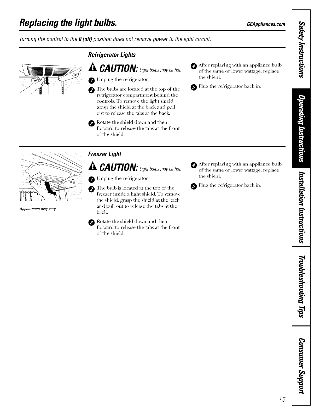
Refrigerator Lights
Appearance may vary
CAUTION:ah,b./bsmayboho_
0 Unplug the refl_geratox:
@ Tile bulbs are located at tile top of tile
refi_igerator compartment behind tile
controls. To reino;e tile light shield,
,grasI ) tile shield at tile back and pull
out to release the tabs at the back.
_]_ Rotate tile shield down and then
fin'ward to release the tabs at the fl'ont
of the shield.
Freezer Light
P' CAUTION:L,_h,b./bsma_b_ho_
Unplug tile reti-igerato_:
0 Tile bulb is located at tile top of tile
freezer inside a light shield. To relnove
the shield, grasp the shield at the back
and pull out to release tile tabs at tile
back.
_Mter replacing with an appliance bulb
of the same or lower wattage, replace
the shield.
0 Plug tile refl-igerator back in.
@ _Mter replacing with an appliance bull)
of the same or lower wattage, replace
the shield.
0 Plug tile refl'igerator back in.
Rotate tile shield down and then
forward to release the tabs at the fl'ont
of the shield.
15
Installation
Refrigerator
Instructions
I Questions? Call 800.GE.CARES (800.432.2737) or Visit our Website at: GEAppliances.com
BEFORE YOU BEGIN
Read these instructions completely
and carefully.
• IMPORTANT - Savethese
instructions for local inspector's use.
• IMPORTANT - Observeall
governing codes and ordinances.
• Note to Installer - Be sure to leave these
instructions with the Consumer.
• Note to Consumer - Keep these
instructions for future reference.
• Skill level - Installation of this appliance
requires basic mechanical skills.
• Completion time - Refrigerator Installation
• Proper installation is the responsibility of
the installer.
In Canada, call 1.800.361.3400 or Visit our Website at: geappliances.ca
PREPARATION (cont.)
WATER SUPPLY TO THE ICEMAKER AND
DISPENSER (ON SOME MODELS)
If the refrigerator has an icemaker, it will have
to be connected to a cold water line. AGE water
supply kit (containing tubing, shutoff valve,
fittings and instructions) is available at extra
cost from your dealer, by visiting our Website
at GEAppliances.com (in Canada at
geappliances.ca) or from Parts and Accessories,
800.626.2002 (In Canada 1.888.261.3055).
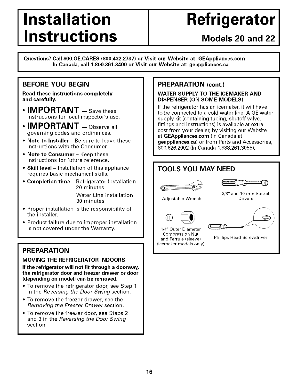
TOOLS YOU MAY NEED
20 minutes
Water Line Installation
30 minutes
Adjustable Wrench
Models 20 and 22
3/8" and 10 mm Socket
I
Drivers
• Product failure due to improper installation
is not covered under the Warranty.
PREPARATION
MOVING THE REFRIGERATOR INDOORS
If the refrigerator will not fit through a doorway,
the refrigerator door and freezer drawer or door
(depending on model) can be removed.
• To remove the refrigerator door, see Step 1
in the Reversing the Door Swing section.
• To remove the freezer drawer, see the
Removing the Freezer Drawer section.
• To remove the freezer door, see Steps 2
and 3 in the Reversing the Door Swing
section.
1/4" Outer Diameter
Compression Nut
and Ferrule (sleeve)
(icemaker models only)
Phillips Head Screwdriver
16
Installation Instructions
INSTALLING THE REFRIGERATOR
REFRIGERATOR LOCATION
• Do not install the refrigerator where the
temperature will go below 60°F (16°C) because it
will not run often enough to maintain proper
temperatures.
• Do not install the refrigerator where the
temperature will go above IO0°F (37°C) because it
will not perform properly.
• Install it on a floor strong enough to support it fully
loaded.
CLEARANCES
Allow the following clearances for ease of installation,
proper air circulation and plumbing and electrical
connections.
Sides 1/8" (4 mm)
Top 1" (25 mm)
Back 1" (25 mm)
REMOVE TOP CAP (onsomemodels)
• IMPORTANT NOTE: This refrigerator is 34-1/2" deep.
Doors and passageways leading to the installation
location must be at least 36" wide in order to
leave the doors and handles attached to the
refrigerator while transporting it into the installation
location. If passageways are less than 36", the
refrigerator doors and handles can easily be scratched
and damaged. The top cap and doors can be removed
to allow the refrigerator to be safely moved indoors.
Start with Step A.
• If it is not necessary to remove doors, skip Step A.
Leave tape and all packaging on doors until the
refrigerator is in the final location.
• SKID REMOVAL: lilt refrigerator to each side to
remove skid.
• NOTE: Use a padded hand truck to move this
refrigerator. Place the refrigerator on the hand
truck with a side against the truck. We strongly
recommend that TWO PEOPLE move and complete
this installation.
[] Locate and remove the two Phillips head screws
on the top of the refrigerator. Remove the two
screws on each side at the rear of the top cap.
Lift off and remove top cap.
[] Remove the fresh-food door. Refer to Steps 1
through 3 of "Reversing the Door Swing" section.
[] Remove the bottom freezer drawer. Refer to
"Removing Freezer Drawer" section.
[] Move refrigerator to the installation location.
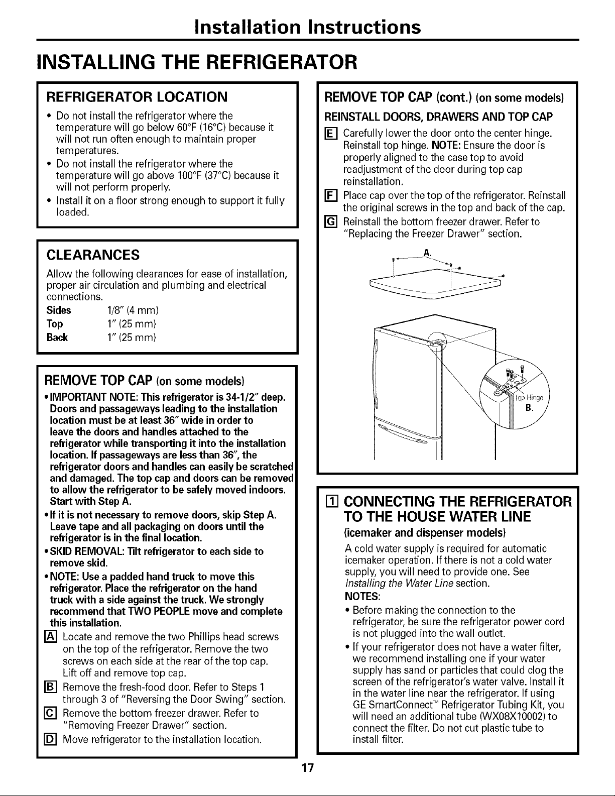
REMOVE TOP CAP (cont.) (onsomemodels)
REINSTALL DOORS, DRAWERS AND TOP CAP
[] Carefully lower the door onto the center hinge.
Reinstall top hinge. NOTE: Ensure the door is
properly aligned to the case top to avoid
readjustment of the door during top cap
reinstallation.
[] Place cap over the top of the refrigerator. Reinstall
the original screws in the top and back of the cap.
[] Reinstall the bottom freezer drawer. Refer to
"Replacing the Freezer Drawer" section.
A,
[] CONNECTING THE REFRIGERATOR
TO THE HOUSE WATER LINE
(icemaker and dispenser models)
A cold water supply is required for automatic
icemaker operation. If there is not a cold water
supply, you will need to provide one. See
Installing the Water Line section.
NOTES:
• Before making the connection to the
refrigerator, be sure the refrigerator power cord
is not plugged into the wall outlet.
• If your refrigerator does not have a water filter,
we recommend installing one if your water
supply has sand or particles that could clog the
screen of the refrigerator's water valve. Install it
in the water line near the refrigerator. If using
GE SmartConnect TM Refrigerator Tubing Kit, you
will need an additional tube (WXO8XIO002) to
connect the filter. Do not cut plastic tube to
install filter.
17
Installation Instructions
INSTALLING THE REFRIGERATOR (cont,)
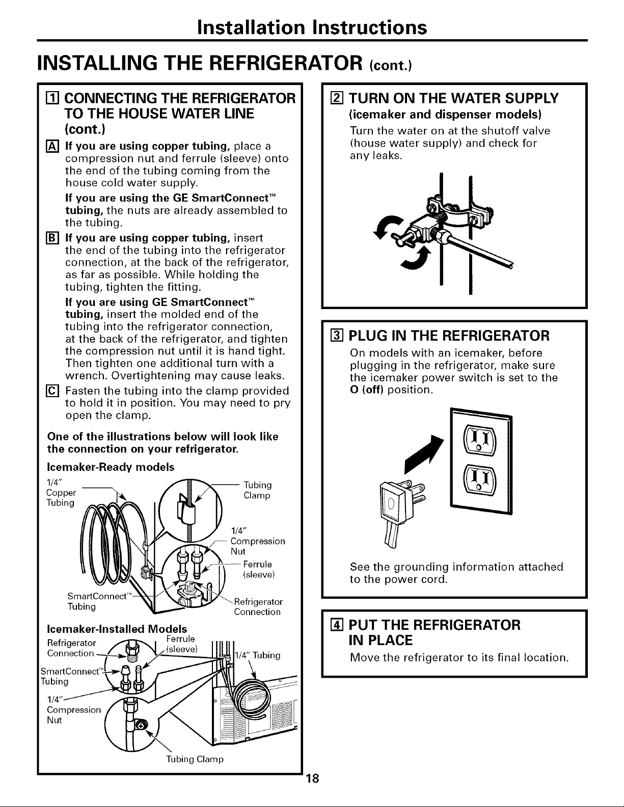
[] CONNECTING THE REFRIGERATOR
TO THE HOUSE WATER LINE
(cont.)
[] If you are using copper tubing, place a
compression nut and ferrule (sleeve) onto
the end of the tubing coming from the
house cold water supply.
If you are using the GE SmartConnect TM
tubing, the nuts are already assembled to
the tubing.
[] If you are using copper tubing, insert
the end of the tubing into the refrigerator
connection, at the back of the refrigerator,
as far as possible. While holding the
tubing, tighten the fitting.
If you are using GE SmartConnect TM
tubing, insert the molded end of the
tubing into the refrigerator connection,
at the back of the refrigerator, and tighten
the compression nut until it is hand tight.
Then tighten one additional turn with a
wrench. Overtightening may cause leaks.
[] Fasten the tubing into the clamp provided
to hold it in position. You may need to pry
open the clamp.
[] TURN ON THE WATER SUPPLY
(icemaker and dispenser models)
Turn the water on at the shutoff valve
(house water supply) and check for
any leaks.
[] PLUG IN THE REFRIGERATOR
On models with an icemaker, before
plugging in the refrigerator, make sure
the icemaker power switch is set to the
O (off) position.
One of the illustrations below will look like
the connection on your refrigerator.
Icemaker-Ready models
1/4" -- Tubing
Copper Clamp
Tubing
1/4"
Compression
Nut
(sleeve)
SmartConnect T_
Tubing gerator
Icemaker-lnstalled Models
Refrigerator Ferrule
Connection
Connection
1/4" Tubing
See the grounding information attached
to the power cord.
[] PUT THE REFRIGERATOR
IN PLACE
Move the refrigerator to its final location.
18

Installation Instructions
[] ATTACH REFRIGERATOR
DOOR HANDLE
[] Look for an arrow label on the front of
the handle.
If the door mounting screws are located
on the left side of the door, hold the
handle so the arrow points to the right
(arrow is at the top of the handle).
If the door mounting screws are located
on the right side of the door, hold the
handle so the arrow points to the left
(arrow is at the bottom of the handle).
Door
handle
on left
side
Door
handle
on right
side
[] ATTACH REFRIGERATOR
DOOR HANDLE (cont.)
[] Holding the handle with both hands,
press it firmly against the front of the
door and slide the handle down. This
may require some force.
Screws
mounted
on door
Keyhole slots
on back of handle
[] Align keyhole slots on the top and bottom
of the back of the handle with the screws
mounted on the front of the door. Press
the handle against the door front, making
sure that the screws go into the keyhole
slots.
19
Installation Instructions
INSTALLING THE REFRIGERATOR (cont,)
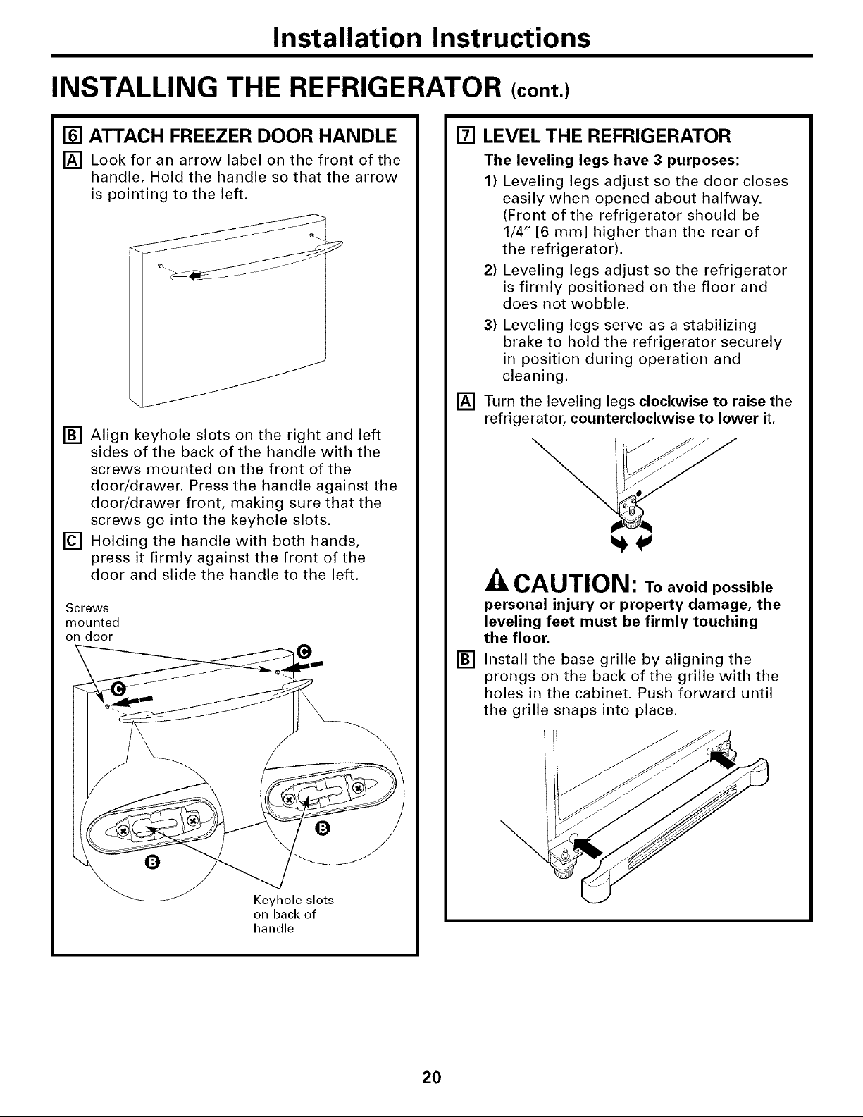
[] ATTACH FREEZER DOOR HANDLE
[] Look for an arrow label on the front of the
handle. Hold the handle so that the arrow
is pointing to the left.
[] Align keyhole slots on the right and left
sides of the back of the handle with the
screws mounted on the front of the
door/drawer. Press the handle against the
door/drawer front, making sure that the
screws go into the keyhole slots,
[] Holding the handle with both hands,
press it firmly against the front of the
door and slide the handle to the left.
Screws
mounted
on door
[] LEVEL THE REFRIGERATOR
The leveling legs have 3 purposes:
1) Leveling legs adjust so the door closes
easily when opened about halfway.
(Front of the refrigerator should be
1/4" [6 mm] higher than the rear of
the refrigerator).
2) Leveling legs adjust so the refrigerator
is firmly positioned on the floor and
does not wobble.
3) Leveling legs serve as a stabilizing
brake to hold the refrigerator securely
in position during operation and
cleaning.
[] Turn the leveling legs clockwise to raise the
refrigerator, counterclockwise to lower it.
ZkCAUTION: Toavoidpossible
personal injury or property damage, the
leveling feet must be firmly touching
the floor.
[]
Install the base grille by aligning the
prongs on the back of the grille with the
holes in the cabinet. Push forward until
the grille snaps into place.
0
0
Keyhole slots
on back of
handle
20
Installation Instructions
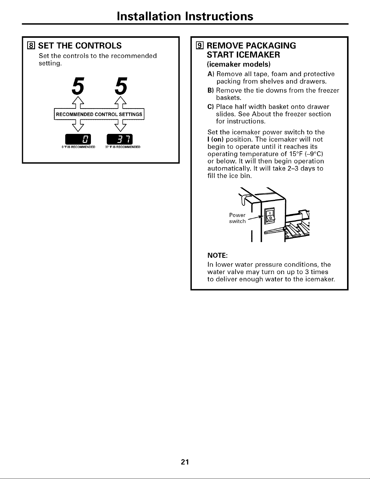
[] SET THE CONTROLS
Set the controls to the recommended
setting.
5 5
[.EOOMME.OEOCO.T.OLSE ..OS]
=
f_
0 "F IS RECOMMENDED 37 _F IS RECOMMENDED
[] REMOVE PACKAGING
START ICEMAKER
(icemaker models)
A) Remove all tape, foam and protective
packing from shelves and drawers.
B) Remove the tie downs from the freezer
baskets.
C) Place half width basket onto drawer
slides. See About the freezer section
for instructions.
Set the icemaker power switch to the
I (on) position. The icemaker will not
begin to operate until it reaches its
operating temperature of 15°F (-9°C)
or below. It will then begin operation
automatically. It will take 2-3 days to
fill the ice bin.
NOTE:
In lower water pressure conditions, the
water valve may turn on up to 3 times
to deliver enough water to the icemaker.
21
Installation Instructions
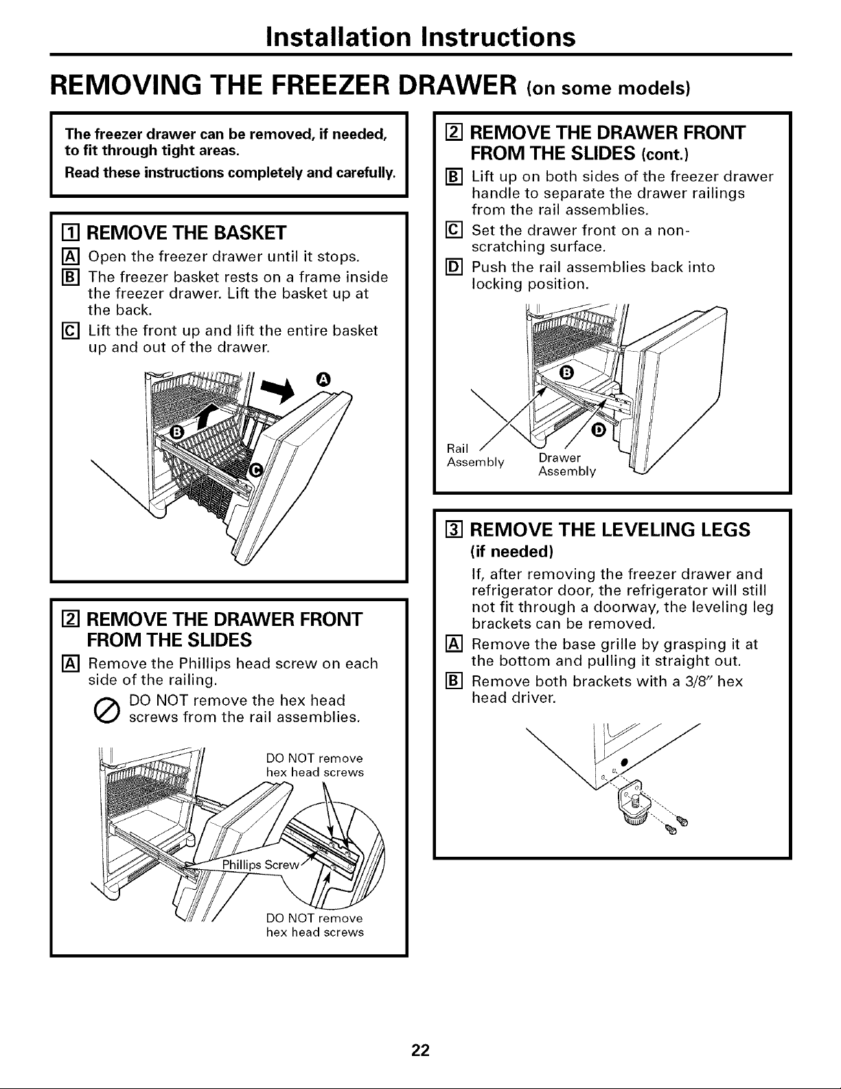
REMOVING THE FREEZER DRAWER (on some models)
The freezer drawer can be removed, if needed,
to fit through tight areas.
Read these instructions completely and carefully.
[] REMOVE THE BASKET
[] Open the freezer drawer until it stops.
[] The freezer basket rests on a frame inside
the freezer drawer. Lift the basket up at
the back.
[] Lift the front up and lift the entire basket
up and out of the drawer.
\
[] REMOVE THE DRAWER FRONT
FROM THE SLIDES
[] Remove the Phillips head screw on each
side of the railing.
(_ DO NOT remove the hex head
screws from the rail assemblies.
[] REMOVE THE DRAWER FRONT
FROM THE SLIDES (cont.)
[] Lift up on both sides of the freezer drawer
handle to separate the drawer railings
from the rail assemblies.
[] Set the drawer front on a non-
scratching surface.
[] Push the rail assemblies back into
locking position.
Rail
Assembly Drawer
Assembly
[] REMOVE THE LEVELING LEGS
(if needed)
If, after removing the freezer drawer and
refrigerator door, the refrigerator will still
not fit through a doorway, the leveling leg
brackets can be removed.
[] Remove the base grille by grasping it at
the bottom and pulling it straight out.
[] Remove both brackets with a 3/8" hex
head driver.
DO NOT remove
hex head screws
DO NOT remove
hex head screws
22
Installation Instructions
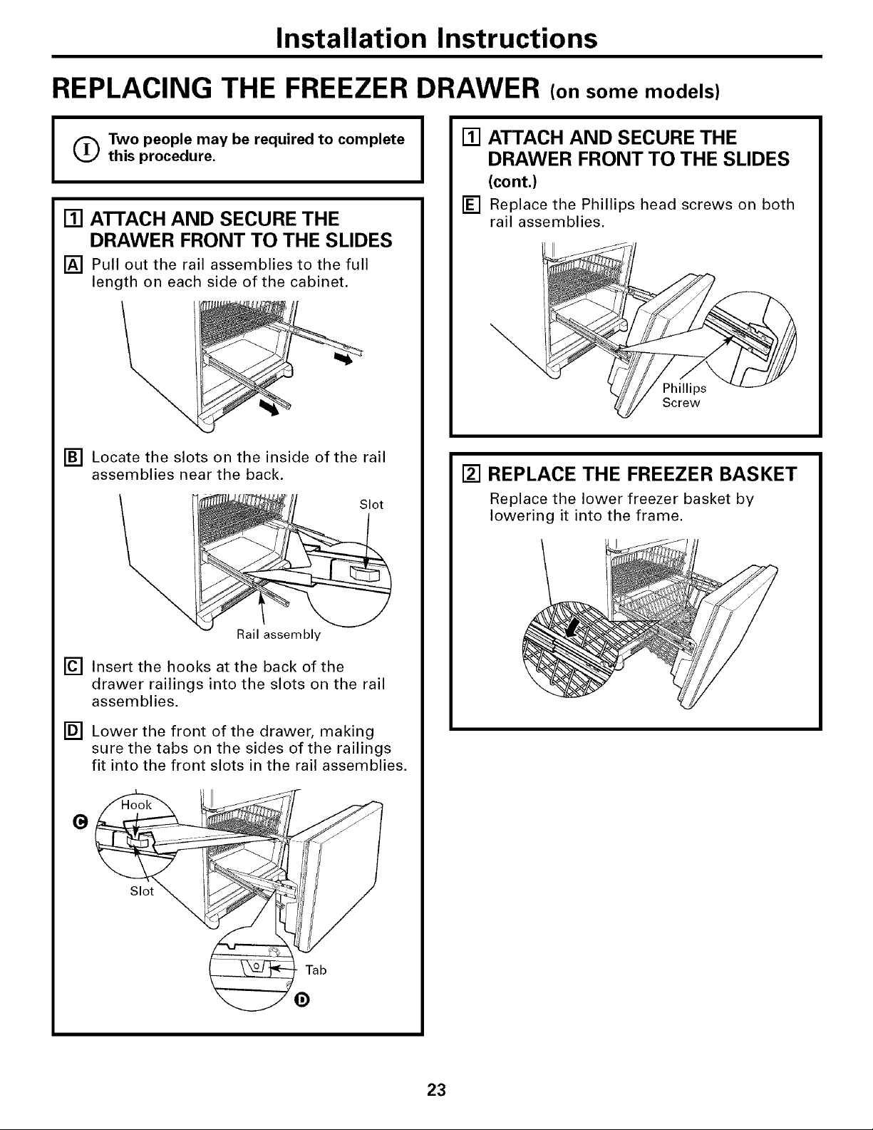
REPLACING THE FREEZER DRAWER (on some models)
(_Two people may be required to complete
I
this procedure.
[] ATTACH AND SECURE THE
DRAWER FRONT TO THE SLIDES
[] Pull out the rail assemblies to the full
length on each side of the cabinet.
[] Locate the slots on the inside of the rail
assemblies near the back.
Slot
[] ATTACH AND SECURE THE
DRAWER FRONT TO THE SLIDES
(cont.)
[] Replace the Phillips head screws on both
rail assemblies.
Phillips
Screw
[] REPLACE THE FREEZER BASKET
Replace the lower freezer basket by
lowering it into the frame.
Rail assembly
[] Insert the hooks at the back of the
drawer railings into the slots on the rail
assemblies.
[] Lower the front of the drawer, making
sure the tabs on the sides of the railings
fit into the front slots in the rail assemblies,
G
Slot
Tab
23
Installation Instructions
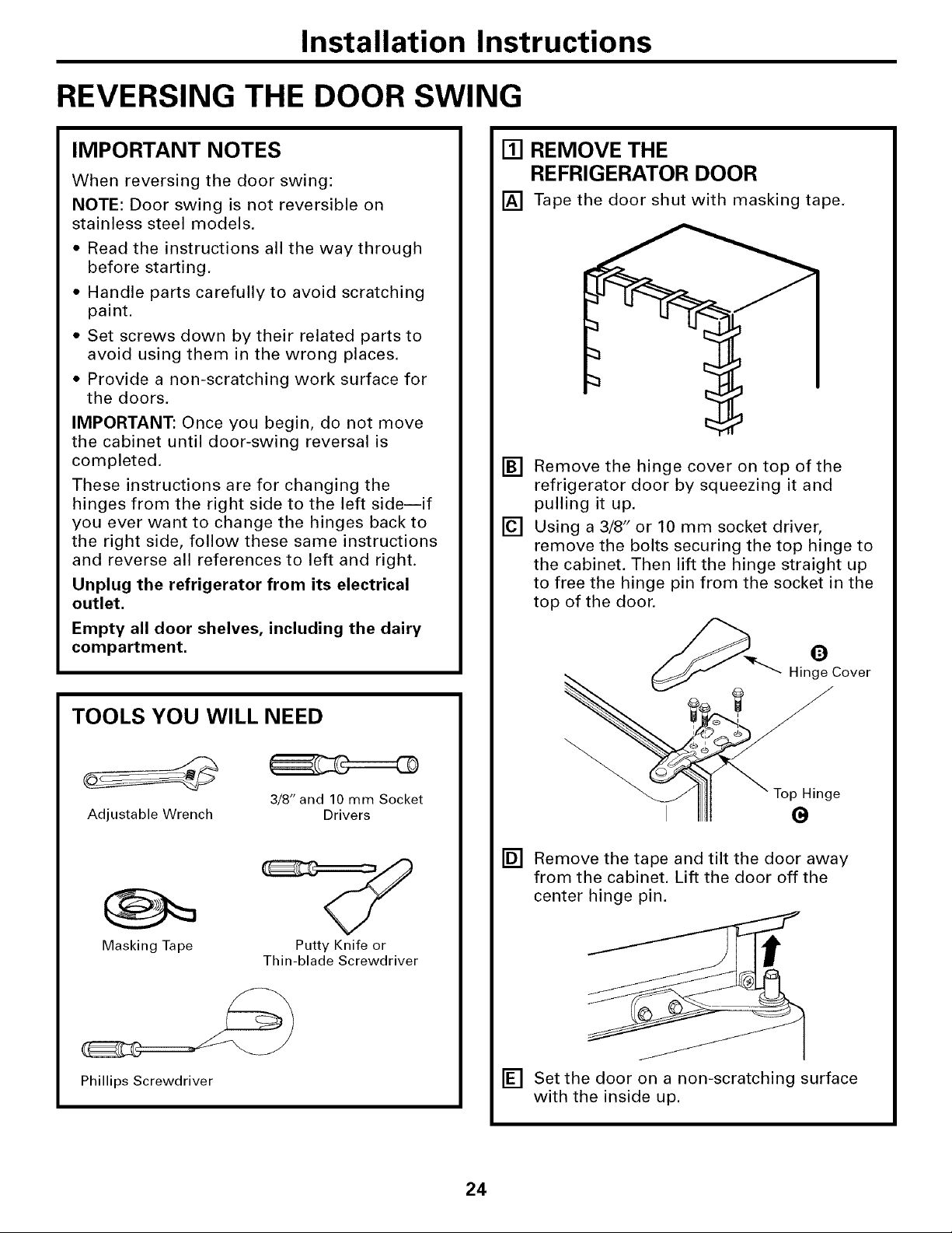
REVERSING THE DOOR SWING
IMPORTANT NOTES
When reversing the door swing:
NOTE: Door swing is not reversible on
stainless steel models.
• Read the instructions all the way through
before starting.
• Handle parts carefully to avoid scratching
paint.
• Set screws down by their related parts to
avoid using them in the wrong places.
• Provide a non-scratching work surface for
the doors.
IMPORTANT: Once you begin, do not move
the cabinet until door-swing reversal is
completed.
These instructions are for changing the
hinges from the right side to the left side--if
you ever want to change the hinges back to
the right side, follow these same instructions
and reverse all references to left and right.
Unplug the refrigerator from its electrical
outlet,
Empty all door shelves, including the dairy
compartment.
[] REMOVE THE
REFRIGERATOR DOOR
[] Tape the door shut with masking tape.
[]
Remove the hinge cover on top of the
refrigerator door by squeezing it and
pulling it up.
[]
Using a 3/8" or 10 mm socket driver,
remove the bolts securing the top hinge to
the cabinet. Then lift the hinge straight up
to free the hinge pin from the socket in the
top of the door.
__ Hing_e COver
TOOLS YOU WILL NEED
3/8" and 10 mm Socket
Adjustable Wrench
Masking Tape Putty Knife or
Thin-blade Screwdriver
Phillips Screwdriver
Drivers
e
[]
Remove the tape and tilt the door away
from the cabinet. Lift the door off the
center hinge pin.
[] Set the door on a non-scratching surface
with the inside up.
24
Installation Instructions
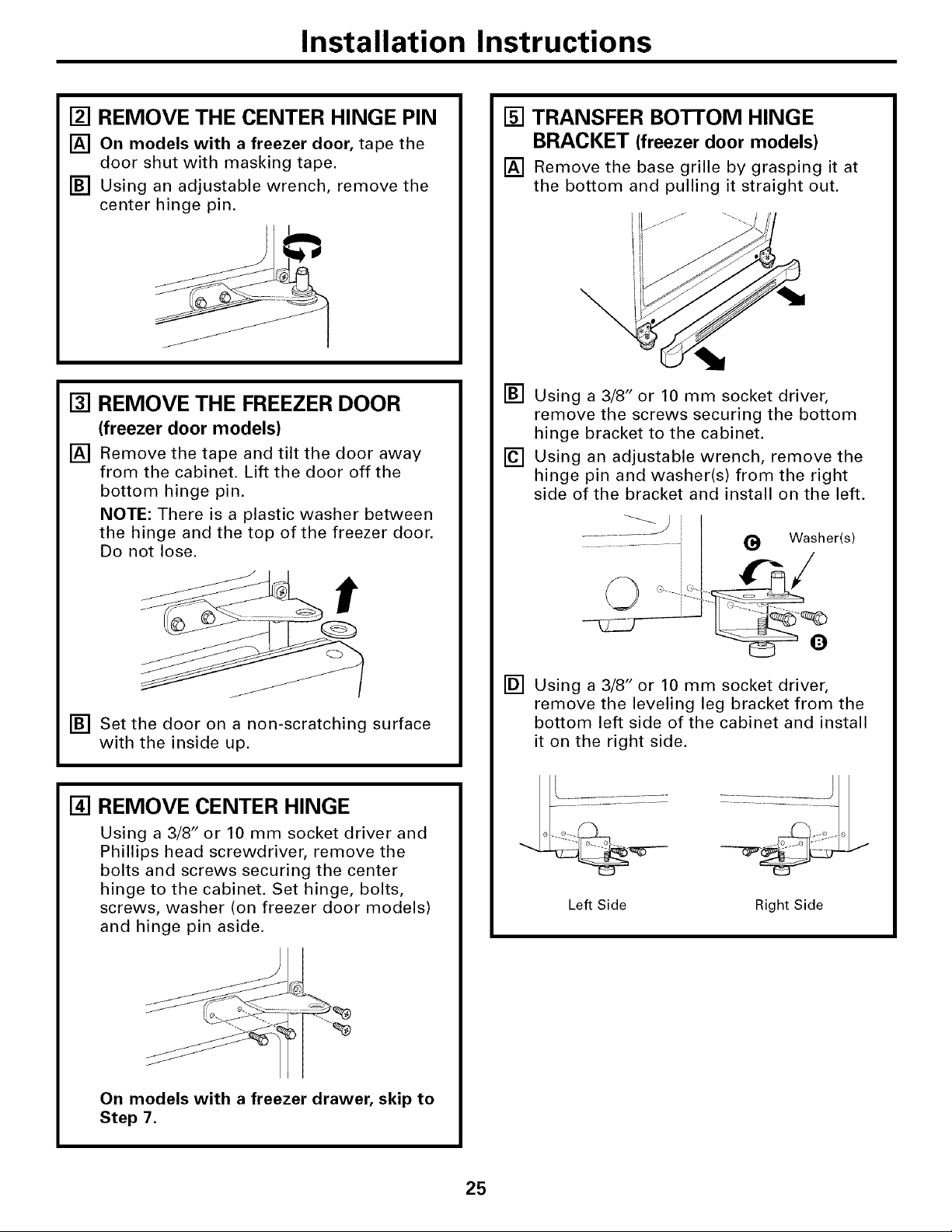
[] REMOVE THE CENTER HINGE PIN
[] On models with a freezer door, tape the
door shut with masking tape.
[] Using an adjustable wrench, remove the
center hinge pin.
[] REMOVE THE FREEZER DOOR
(freezer door models)
[] Remove the tape and tilt the door away
from the cabinet. Lift the door off the
bottom hinge pin.
NOTE: There is a plastic washer between
the hinge and the top of the freezer door.
Do not lose.
[] TRANSFER BOTTOM HINGE
BRACKET (freezer door models)
[] Remove the base grille by grasping it at
the bottom and pulling it straight out.
\
[] Using a 3/8" or 10 mm socket driver,
remove the screws securing the bottom
hinge bracket to the cabinet.
[] Using an adjustable wrench, remove the
hinge pin and washer(s) from the right
side of the bracket and install on the left.
[] Set the door on a non-scratching surface
with the inside up.
[] REMOVE CENTER HINGE
Using a 3/8" or 10 mm socket driver and
Phillips head screwdriver, remove the
bolts and screws securing the center
hinge to the cabinet. Set hinge, bolts,
screws, washer (on freezer door models)
and hinge pin aside.
On models with a freezer drawer, skip to
Step 7.
[] Using a 3/8" or 10 mm socket driver,
remove the leveling leg bracket from the
bottom left side of the cabinet and install
it on the right side.
Left Side Right Side
25
Installation Instructions
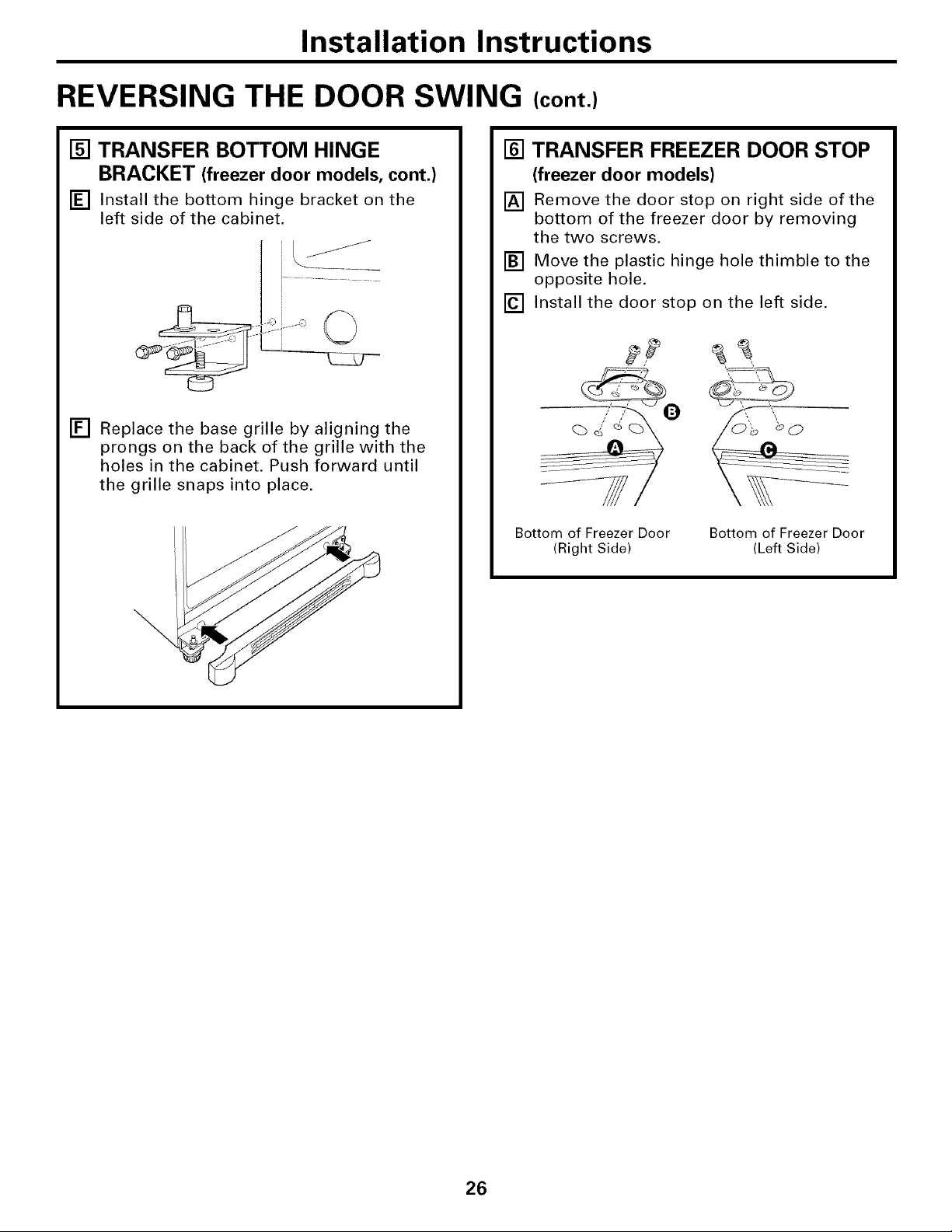
REVERSING THE DOOR SWING (cont.)
[] TRANSFER BOTTOM HINGE
BRACKET (freezer door models, cont.)
[] Install the bottom hinge bracket on the
left side of the cabinet.
[] Replace the base grille by aligning the
prongs on the back of the grille with the
holes in the cabinet. Push forward until
the grille snaps into place.
[] TRANSFER FREEZER DOOR STOP
(freezer door models)
[] Remove the door stop on right side of the
bottom of the freezer door by removing
the two screws.
[] Move the plastic hinge hole thimble to the
opposite hole.
[] Install the door stop on the left side.
Bottom of Freezer Door
(Right Side)
Bottom of Freezer Door
(Left Side)
26
Installation Instructions
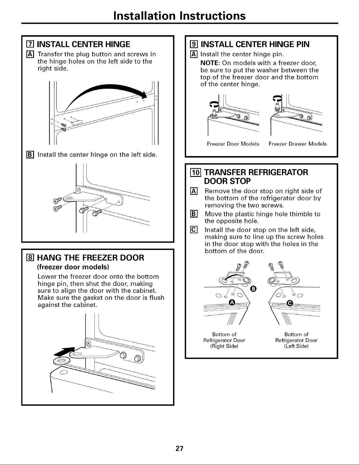
[] INSTALL CENTER HINGE
[] Transfer the plug button and screws in
the hinge holes on the left side to the
right side.
[] Install the center hinge on the left side.
[] HANG THE FREEZER DOOR
(freezer door models)
Lower the freezer door onto the bottom
hinge pin, then shut the door, making
sure to align the door with the cabinet.
Make sure the gasket on the door is flush
against the cabinet.
[] INSTALL CENTER HINGE PIN
[] Install the center hinge pin.
NOTE: On models with a freezer door,
be sure to put the washer between the
top of the freezer door and the bottom
of the center hinge,
Freezer Door Models Freezer Drawer Models
TRANSFER REFRIGERATOR
[]
DOOR STOP
[]
Remove the door stop on right side of
the bottom of the refrigerator door by
removing the two screws.
[]
Move the plastic hinge hole thimble to
the opposite hole.
[]
Install the door stop on the left side,
making sure to line up the screw holes
in the door stop with the holes in the
bottom of the door.
27
Bottom of
Refrigerator Door
(Right Side)
Bottom of
Refrigerator Door
(Left Side)
Installation Instructions
REVERSING THE DOOR SWING (cont.)
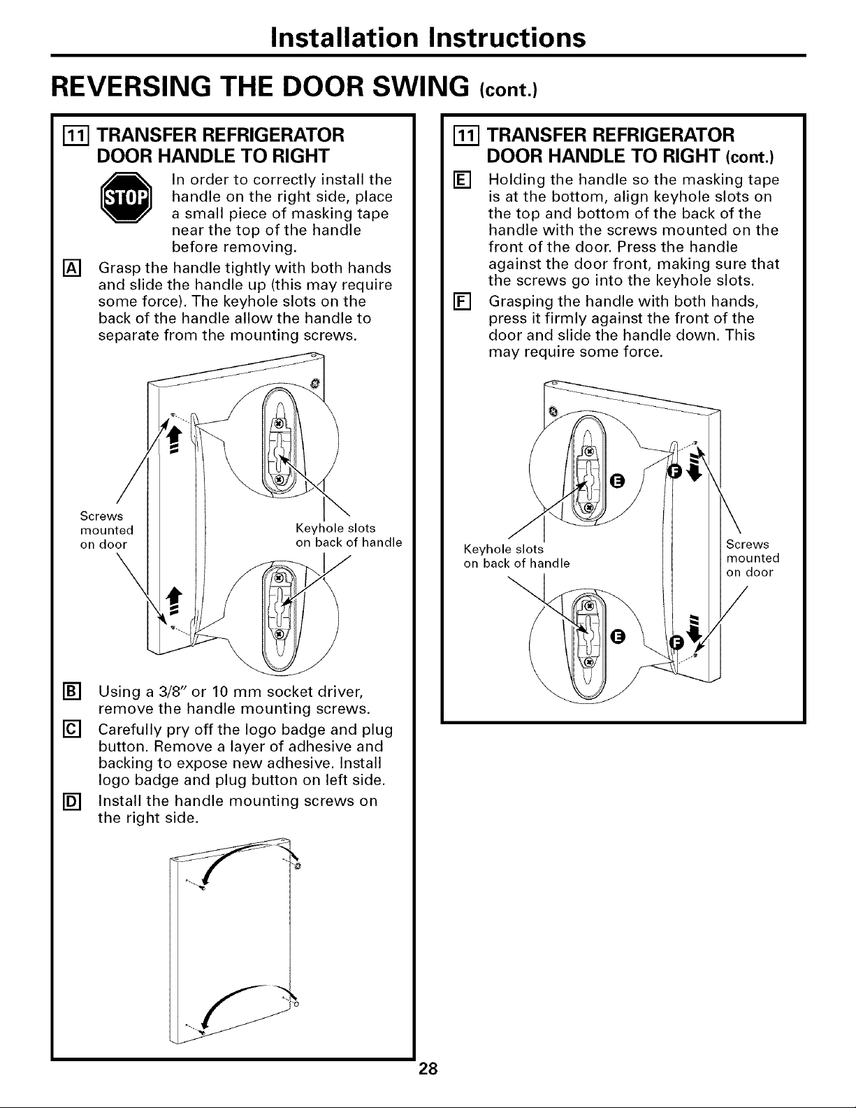
[] TRANSFER REFRIGERATOR
DOOR HANDLE TO RIGHT
In order to correctly install the
handle on the right side, place
a small piece of masking tape
near the top of the handle
before removing.
[]
Grasp the handle tightly with both hands
and slide the handle up (this may require
some force). The keyhole slots on the
back of the handle allow the handle to
separate from the mounting screws.
Screws
mounted
on door
Keyhole slots
on back of handle
\
TRANSFER REFRIGERATOR
DOOR HANDLE TO RIGHT (cont.)
[]
Holding the handle so the masking tape
is at the bottom, align keyhole slots on
the top and bottom of the back of the
handle with the screws mounted on the
front of the door. Press the handle
against the door front, making sure that
the screws go into the keyhole slots.
[]
Grasping the handle with both hands,
press it firmly against the front of the
door and slide the handle down. This
may require some force.
Keyhole slots
on back of handle
Screws
[ mounted
on door
[] Using a 3/8" or 10 mm socket driver,
remove the handle mounting screws.
[] Carefully pry off the logo badge and plug
button. Remove a layer of adhesive and
backing to expose new adhesive. Install
logo badge and plug button on left side.
[] Install the handle mounting screws on
the right side.
28
Installation Instructions
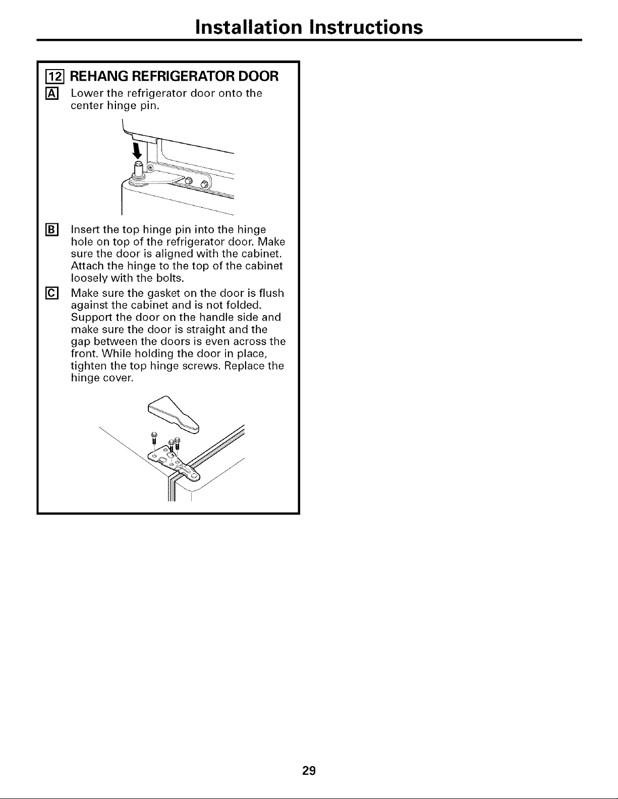
[] REHANG REFRIGERATOR DOOR
[] Lower the refrigerator door onto the
center hinge pin.
[]
Insert the top hinge pin into the hinge
hole on top of the refrigerator door. Make
sure the door is aligned with the cabinet.
Attach the hinge to the top of the cabinet
loosely with the bolts.
[]
Make sure the gasket on the door is flush
against the cabinet and is not folded.
Support the door on the handle side and
make sure the door is straight and the
gap between the doors is even across the
front. While holding the door in place,
tighten the top hinge screws. Replace the
hinge cover,
29
Installation Instructions
INSTALLING THE WATER LINE (ICEMAKER MODELS)
BEFORE YOU BEGIN
Recommended copper water supply kits are
WX8X2, WX8X3 or WX8X4, depending on the
amount of tubing you need. Approved plastic
water supply lines are GE SmartConnect TM
Refrigerator Tubing (WX08X10002,
WX08X10006, WX08X10015 and
WX08X 10025).
When connecting your refrigerator to a GE
Reverse Osmosis Water System, the only
approved installation is with a GE RVKit. For
other reverse osmosis water systems, follow
the manufacturer's recommendations.
If the water supply to the refrigerator is from
a Reverse Osmosis Water Filtration System
AND the refrigerator also has a water filter,
use the refrigerator's filter bypass plug. Using
the refrigerator's water filtration cartridge in
conjunction with the RO filter can result in
hollow ice cubes.
This water line installation is not warranted
by the refrigerator or icemaker manufacturer.
Follow these instructions carefully to
minimize the risk of expensive water damage.
Water hammer (water banging in the pipes)
in house plumbing can cause damage to
refrigerator parts and lead to water leakage
or flooding. Call a qualified plumber to correct
water hammer before installing the water
supply line to the refrigerator.
To prevent burns and product damage, do not
hook up the water line to the hot water line.
If you use your refrigerator before connecting
the water line, make sure the icemaker power
switch is in the O (off) position.
Do not install the icemaker tubing in areas
where temperatures fall below freezing.
When using any electrical device (such as a
power drill) during installation, be sure the
device is double insulated or grounded in a
manner to prevent the hazard of electric
shock, or is battery powered.
All installations must be in accordance with
local plumbing code requirements.
WHAT YOU WILL NEED
J
• Copper or GE SmartConnect TM Refrigerator
Tubing kit, 1/4" outer diameter to connect
the refrigerator to the water supply. If using
copper, be sure both ends of the tubing are
cut square.
To determine how much tubing you need:
measure the distance from the water valve
on the back of the refrigerator to the water
supply pipe. Then add 8' (2.4 m). Be sure
there is sufficient extra tubing (about 8' [2.4 m]
coiled into 3 turns of about 10" [25 cm]
diameter) to allow the refrigerator to move
out from the wall after installation.
GE SmartConnect TMRefrigerator Tubing Kits
are available in the following lengths:
2' (0.6 m) - WXO8XIO002
6' (1.8 m) -WXO8XIO006
15' (4.6 m) - WXO8X10015
25' (7.6 m) - WXO8X10025
Be sure that the kit you select allows at least
8' (2.4 m) as described above.
3O
 Loading...