


GEH-5837B
GE |
INSTRUCTIONS |
|
g Lighting Solutions |
||
Criterion™ Medium Vertical Area |
||
|
READ THOROUGHLY BEFORE INSTALLING
 WARNING
Risk of electric shock
•Turn power off before servicing
–see instructions
WARNING
Risk of fire
•Use supply wire specified on nameplate
GENERAL
This luminaire is designed for outdoor lighting applications, and should not be used in areas of limited ventilation, or in high ambient temperature enclosures. Best results will be obtained if installed and maintained according to the following recommendations.
UNPACKING
This luminaire has been properly packed so that no parts should have been damaged during transit. Inspect to confirm. Do not set unpacked unit on glass lens.
INSTALLATION
Follow installation instructions:
Reflector Rotation: Reflectors may be rotated such that reflector is in any of four positions. This allows for variations in beam aiming. In order to rotate the reflector, the following procedure should be followed.
Reflector Retainer Clips
Top View of Housing with Cover removed
Figure 1
1.Open the fixture cover and lock brace.
2.Remove socket holder from reflector noting socket position. Rotate retainer clips to a position off flange of the reflector. (see figure 1)
3.Rotate reflector to desired position and rotate four retainer clips from over flange.
4.Install Socket/lamp holder to proper position (see Figure 7).
5.Close cover and latch.
MOUNTING
CAUTION
Unit will fall if not installed properly
• Follow installation instructions
Note: Power leads should be pulled as mounting parts are assembled, verifying that leads are free and not pinched.
ARCHITECTURAL MOUNTING (ARM):
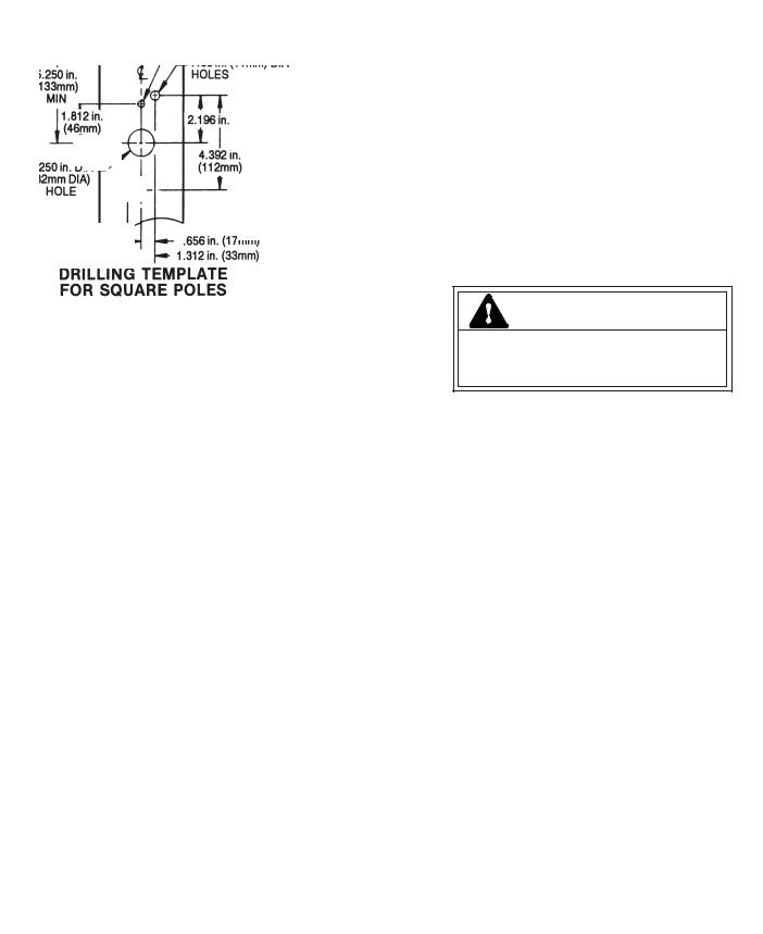
USE WITH SQUARE POLES PRE-DRILLED PER FIGURE 2:
1.Install nut plate (see figure 3) inside pre-drilled pole. Secure nut plate to inside of pole with screw provided.
2.Install the two (2) studs ensuring that they fully penetrate the nut plate.
3.Align upper and lower guides on inside of mounting arm with their respective studs and slide it into place against pole. Arm is tapered. Make sure that the short side of arm is on top (see figure 4). Note: Wiring for unit should be pulled through arm at this time.
4.Open Luminaire cover, remove SnapDrive™ electrical system to reduce weight. (See instructions for correct SnapDrive removal.)
These instructions do not purport to cover all details or variations in equipment nor to provide for every possible contingency to be met in connection with installation, operation or maintenance. Should further information be desired or should particular problems arise which are not covered sufficiently for the purchaser’s purposes, the matter should be referred to GE Lighting Solutions.
5.Install the luminaire and secure with flat washers and lock nuts provided (see figure 4). Align the system as the nuts are tightened. Spacer washers are supplied. Several washers will be needed for the top stud. (Note: Wiring for unit should be pulled through arm at this time)
6.Install SnapDrive (See below instruction)
Caution: Ensure that nuts fully engage the two studs. Correct tightening of studs nuts is important to ensure proper function of mounting system. Torque nuts to 18-22 foot pounds
(24
|
|
|
.312 in. (8mm) DIA |
|
|
|
H O L E |
|
5.250 in. |
|
.438 in. (11mm) DIA |
|
|
H O L E |
|
|
(133mm) |
|
|
|
|
|
|
|
M I N |
|
|
|
1.812 in. |
|
2.196 in. (56mm) |
|
(46mm) |
|
|
|
|
|
4.392 in. |
|
1.250 in. DIA |
|
(112mm) |
|
(32mm DIA) |
|
|
|
H O L E |
|
|
|
|
.656 in. (17mm) |
|
|
|
1.312 in. (33mm) |
|
Figure 2 |
|
|
|
|
|
|
NUTS (3/8-16) |
|
MOUNTING |
ARM |
W A S H E R S |
|
|
||
(1/4-20) |
SCREW |
|
|
SQUARE |
POLE |
|
|
NUT PLATE |
|
|
|
S T U D S
Figure 3
S H O R T |
COVER |
SPACER WASHERS
NUT AND M O U N T I N G W A S H E R S
A R M
OTHER MOUNTINGS
Round Pole Adapters are also available for use with housings machined with a straight hole pattern. Installation is similar to the Architectural Mounting.
Follow installation instructions
|
.438 in. (11mm) |
|
5.250 in. |
D I A |
|
H O L E |
||
(133mm) |
||
|
||
M I N |
2.719 in. |
|
|
(69mm) |
|
|
5.438 in. |
|
.750 in. DIA |
(138mm) |
|
( 1 9 M M |
|
|
D I A ) |
|
|
H O L E |
|
Unit will fall if not installed properly
• Follow installation instructions
WIRING
Make all electrical connections in accordance with all applicable code requirements (National Electrical Code, Canadian Electrical Code and applicable local Codes).
The customer must provide strain relief for the incoming power in the pole top.
1.Verify that supply voltage is correct by comparing it to nameplate.
2.Route wire harness leads from luminaire through arm and into top of pole. Connect wire harness to supply wire and return to interior pole.
Supply wiring entering from pole to interior terminal board must be routed through the wiring clips
(see figure 5). Wires must not touch the reflector.
3.Connect ground lead to the green lead, green ground screw on housing or terminal block provided.
4.Install slotted grommet around supply wires for IP65 rating.
L O N G |
G L A S S |
|
 Loading...