


e i s e s
inin n n s i
LOGIQ 500
Quick Start Guide 2276613±100
A Training in Partnership Program
TiPTM


e i s e s
%$ #
D "$ 7 & #
L % $"$ %
h a c c
! "$ D %$ $

Regulatory Requirement
This product complies with regulatory requirements of the following European Directive 93/42/EEC concerning medical devices
This Quick Start Guide is a reference for LOGIQt 500 PRO Series. It applies to all versions of 6.0 software for the LOGIQt 500.
GE Medical Systems
GE Medical Systems: Telex 3797371
P.O. Box 414, Milwaukee, Wisconsin 53201 U.S.A.
(Asia, Pacific, Latin America, North America)
GE Ultrascall: Tel: +49 (0) 212 28 02 208
Deutschland GmbH & Co KG
Beethovenstraûe 239, Postfach 11 05 60, D±42655 Solingen
GERMANY

REV |
DATE |
REASON FOR CHANGE |
|
|
|
0 |
July 10, 2000 |
Initial Release |
|
|
|
|
|
L P |
P |
|
M |
M |
|
|
|
|
P |
|
|
M |
M |
|
|
|
|
|
|
|
TiP Cover Page |
N/A |
Title Page |
0 |
Revision History A and B |
0 |
Quick Start 1 thru Quick Start 40 |
0 |
LOGIQt 500 Quick Start Guide
2276613±100 Rev. 0
Revision History A

Revision History B
LOGIQt 500 Quick Start Guide
2276613±100 Rev. 0

Introduction
The Quick Start Guide (TRANSLATED) provides a step-by-step description of the basic features and operation of the LOGIQt 500. It is intended to be used in conjunction with the Basic User Manual in order to provide the information necessary to operate the system safely.
The Quick Start Guide takes the user from system familiarization through power on, patient data entry, exam category/preset selection, scan modes/adjustments, basic measurements, report pages, recording images and power off.
The LOGIQt 500 manuals are written for users who are familiar with basic ultrasound principals and techniques. They do not include sonography training or clinical procedures.
Prescription Device (for USA only)
CAUTION: United States law restricts this device to sale or use by or on the order of a physician.
LOGIQt 500 Quick Start Guide
2276613±100 Rev. 0
Quick Start 1
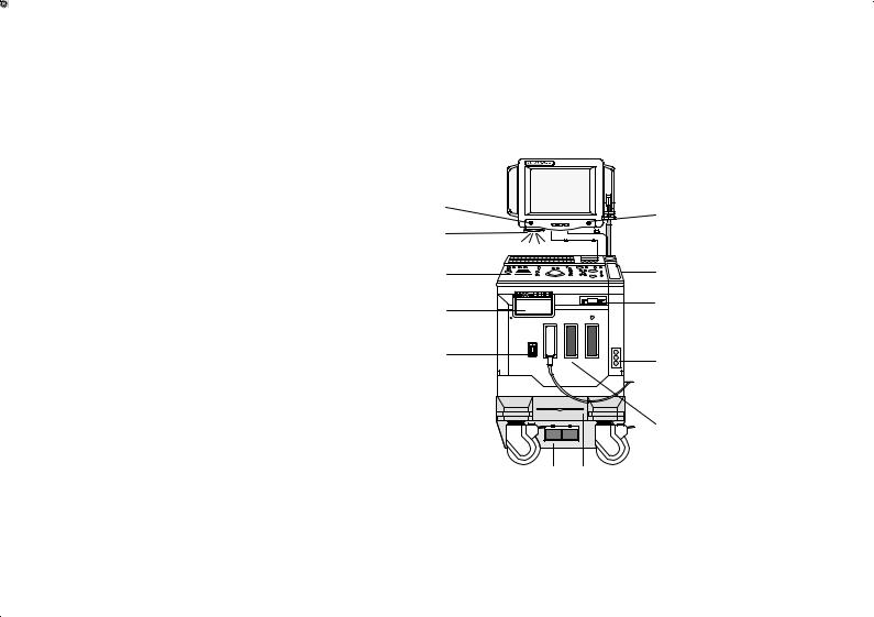
Front View
The following are major features of the LOGIQt 500 system console. Most features come with the standard configuration, while other features are options to the standard console.
1.VCR Microphone
2.Probe Holder
3.MOD Drive
4.Physio Panel *
5.Probe Connectors (3 ports)
6.Air Filter
7.Power Supply Filter
8.On/Off Switch
9.B/W Page Printer *
10.Keyboard
11.Keyboard Task Light
12.Task Light Switch
*= optional feature or accessory
12
11
10
9
8
1
2
3
4
5
7 6
Quick Start 2
LOGIQt 500 Quick Start Guide
2276613±100 Rev. 0
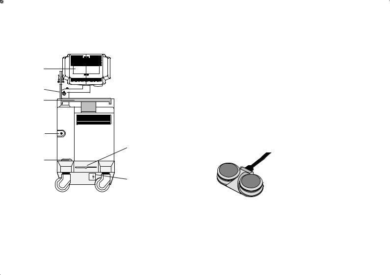
Back View
7
6
5
4
3
1 ON
ON
0 OFF
2
1
1.Circuit Breaker
2.Air Filter
3.Cable Access
4.Peripheral Cable Access Door
5.Handle for Pushing
6.Monitor Arm Swivel Lock
7.Color Monitor
Optional Freeze/Record Foot Switch
Freeze
Record
LOGIQt 500 Quick Start Guide
2276613±100 Rev. 0
Quick Start 3

Power On
To connect the system to the electrical supply:
SEnsure that the wall outlet is a minimum 20 amp dedicated circuit for 120 VAC (USA) or 7.5
amp dedicated circuit for 220±240 VAC (Europe).
S Make sure that the power switch is turned off.
SUnwrap the power cable. Make sure to allow sufficient slack in the cable so that the plug is not pulled out of the wall if the system is moved slightly.
SPush the power plug securely into the wall outlet.
To power on the system, ensure that the Circuit Breaker, located on the back of the power supply near the bottom of the unit, is turned on.
|
Press the Power On Power Off/Stand-by switch, located to the left of the probe connectors, to |
On |
the on position. |
Quick Start 4
LOGIQ 500 Quick Start Guide
2276613±100 Rev. 0
Power On (cont'd)
During power up, the screen display changes as the system runs its self diagnostics.
Start of diagnostic
XXXXXXX |
Version X.XX |
XXXXXXX |
Version X.XX |
Version X.XX |
End of |
diagnostic |
LOGIQt 500 Quick Start Guide
2276613±100 Rev. 0
Quick Start 5

Control Panel Layout
1 |
2 |
3 |
Keyboard
Keyboard controls have been arranged according to function and usage. This helps minimize operator movement while scanning.
1. Alphanumeric Keys
2. New Patient
3. Probe Select
4. Soft Menu Controls
↓
5. Doppler and CFM
"yA


6. User Define
7. Mode, Display and Record
8. Measurements/Annotations
9. TGC and Acoustic Output
10. VCR |
"yA |
4
5
6
7
10 |
9 |
8 |
Quick Start 6
LOGIQt 500 Quick Start Guide
2276613±100 Rev. 0

Soft Menu Control Panel
The Soft Menu Display has 8 Top Menu selections (Mode, Preset, Set Up, ECG, Archive, DICOM, AutoSeq and Cine) and 8 Sub Menu selections (varies depending on choice of Top Menu selection) available.
The Top Menu Select key cycles through the top level menu page selections. The far left side top menu is the default selection and its sub-menus are automatically displayed.
The Sub-Menu Select rocker switch cycles to the next ( ") or previous (A ) sub-menu page.
The Sub-Menu rocker switches allow for the increase/decrease of a parameter value or enabling/disabling of a parameter.
Top Menu Select
TOP MENU |
|
B |
Preset |
Set Up |
ECG |
Current |
1 |
||||
Available |
2 |
Frame |
Imaging |
Image |
|
|
|
|
|||
SUB-MENU |
|
Average |
Freq |
Softner |
|
2 |
|
|
Color |
3D |
|
Current |
|
|
|||
4 |
OFF |
3 MHz |
|
Mode |
|
Available |
|
||||
Sub-Menu Select |
|
|
|
||
LOGIQt 500 Quick Start Guide
2276613±100 Rev. 0
Quick Start 7
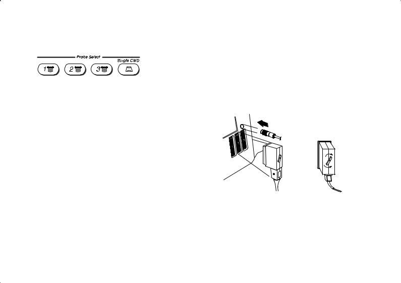
Probe Controls
A probe is activated by pressing the Probe Select key that corresponds to the probe port to which the desired probe is connected. The Single CWD key is used to activate the dedicated continuous wave Doppler (CWD) probe. The active probe key will be brightly lit.
Probe Ports
All imaging probes can be plugged into any of the three probe ports.
The CWD probes can be plugged into the Single CWD port which is located above Probe Port Position 3.
.NOTE: Ensure that the probe port is deactivated and the image is frozen before disconnecting the probe.
lock
unlock
Quick Start 8
LOGIQ 500 Quick Start Guide
2276613±100 Rev. 0
 Loading...