

Page 1

E- 9525 R S e rv er
USERGUIDE
®
Page 2

Page 3

Contents
Chapter 1: Checking Out Your Gateway Server . . . . . . . . . . . . . . . . . . . . . . . 1
Front . . . . . . . . . . . . . . . . . . . . . . . . . . . . . . . . . . . . . . . . . . . . . . . . . . . . . . . . . . . . . . . . . . . . . 2
Control panel . . . . . . . . . . . . . . . . . . . . . . . . . . . . . . . . . . . . . . . . . . . . . . . . . . . . . . . 2
Back . . . . . . . . . . . . . . . . . . . . . . . . . . . . . . . . . . . . . . . . . . . . . . . . . . . . . . . . . . . . . . . . . . . . . . 3
Interior . . . . . . . . . . . . . . . . . . . . . . . . . . . . . . . . . . . . . . . . . . . . . . . . . . . . . . . . . . . . . . . . . . . 4
System board . . . . . . . . . . . . . . . . . . . . . . . . . . . . . . . . . . . . . . . . . . . . . . . . . . . . . . . . . . . . . 5
Connectors . . . . . . . . . . . . . . . . . . . . . . . . . . . . . . . . . . . . . . . . . . . . . . . . . . . . . . . . . 5
Hot-swap backplanes . . . . . . . . . . . . . . . . . . . . . . . . . . . . . . . . . . . . . . . . . . . . . . . . . . . . . . 7
SAS/SATA backplane . . . . . . . . . . . . . . . . . . . . . . . . . . . . . . . . . . . . . . . . . . . . . . . . 7
LED information . . . . . . . . . . . . . . . . . . . . . . . . . . . . . . . . . . . . . . . . . . . . . . . . . . . . . 8
Getting Help . . . . . . . . . . . . . . . . . . . . . . . . . . . . . . . . . . . . . . . . . . . . . . . . . . . . . . . . . . . . . . . 9
Server Companion DVD . . . . . . . . . . . . . . . . . . . . . . . . . . . . . . . . . . . . . . . . . . . . . . 9
Gateway Web site . . . . . . . . . . . . . . . . . . . . . . . . . . . . . . . . . . . . . . . . . . . . . . . . . . . 9
Telephone support . . . . . . . . . . . . . . . . . . . . . . . . . . . . . . . . . . . . . . . . . . . . . . . . . . 9
Chapter 2: Setting Up Your Server. . . . . . . . . . . . . . . . . . . . . . . . . . . . . . . . . 11
Setting up the hardware . . . . . . . . . . . . . . . . . . . . . . . . . . . . . . . . . . . . . . . . . . . . . . . . . . 12
Protecting from power source problems . . . . . . . . . . . . . . . . . . . . . . . . . . . . . . . . . . . . 12
Mounting your server into a cabinet . . . . . . . . . . . . . . . . . . . . . . . . . . . . . . . . . . . . . . . .13
Installing the bezel . . . . . . . . . . . . . . . . . . . . . . . . . . . . . . . . . . . . . . . . . . . . . . . .16
Removing the server from a cabinet . . . . . . . . . . . . . . . . . . . . . . . . . . . . . . . . .17
Starting your server . . . . . . . . . . . . . . . . . . . . . . . . . . . . . . . . . . . . . . . . . . . . . . . . . . . . . . .18
Understanding the power-on self-test . . . . . . . . . . . . . . . . . . . . . . . . . . . . . . . .18
Turning off your server . . . . . . . . . . . . . . . . . . . . . . . . . . . . . . . . . . . . . . . . . . . . .19
Setting up the operating system . . . . . . . . . . . . . . . . . . . . . . . . . . . . . . . . . . . . . . . . . . . 19
Initial hardware settings . . . . . . . . . . . . . . . . . . . . . . . . . . . . . . . . . . . . . . . . . . . . . . . . . . .19
Chapter 3: Maintaining Your Server . . . . . . . . . . . . . . . . . . . . . . . . . . . . . . . 21
Caring for your server . . . . . . . . . . . . . . . . . . . . . . . . . . . . . . . . . . . . . . . . . . . . . . . . . . . . .22
Cleaning your server . . . . . . . . . . . . . . . . . . . . . . . . . . . . . . . . . . . . . . . . . . . . . . .22
Preparing for system recovery . . . . . . . . . . . . . . . . . . . . . . . . . . . . . . . . . . . . . . . . . . . . .23
Recording the BIOS configuration . . . . . . . . . . . . . . . . . . . . . . . . . . . . . . . . . . . . 23
System administration . . . . . . . . . . . . . . . . . . . . . . . . . . . . . . . . . . . . . . . . . . . . . . . . . . . .23
Gateway Systems Manager . . . . . . . . . . . . . . . . . . . . . . . . . . . . . . . . . . . . . . . . . 23
Server security . . . . . . . . . . . . . . . . . . . . . . . . . . . . . . . . . . . . . . . . . . . . . . . . . . . . . 24
Identifying your server . . . . . . . . . . . . . . . . . . . . . . . . . . . . . . . . . . . . . . . . . . . . . . . . . . . . 24
Updating the baseboa r d manageme n t controll er firmware . . . . . . . . . . . . . . . . . . .25
Using your Server Companion DVD . . . . . . . . . . . . . . . . . . . . . . . . . . . . . . . . . . . . . . . . . 25
Server Companion DVD contents . . . . . . . . . . . . . . . . . . . . . . . . . . . . . . . . . . . .25
Viewing documents . . . . . . . . . . . . . . . . . . . . . . . . . . . . . . . . . . . . . . . . . . . . . . . .25
Installing drivers and programs . . . . . . . . . . . . . . . . . . . . . . . . . . . . . . . . . . . . .26
Booting from the Server Companion DVD . . . . . . . . . . . . . . . . . . . . . . . . . . . . .27
Chapter 4: Installing Components. . . . . . . . . . . . . . . . . . . . . . . . . . . . . . . . . . 29
Preparing to install components . . . . . . . . . . . . . . . . . . . . . . . . . . . . . . . . . . . . . . . . . . . . 30
Selecting a place to work . . . . . . . . . . . . . . . . . . . . . . . . . . . . . . . . . . . . . . . . . . .30
Gathering the tools you need . . . . . . . . . . . . . . . . . . . . . . . . . . . . . . . . . . . . . . .30
i
Page 4

Contents
Getting Help . . . . . . . . . . . . . . . . . . . . . . . . . . . . . . . . . . . . . . . . . . . . . . . . . . . . . . .30
Preventing static electricity discharge . . . . . . . . . . . . . . . . . . . . . . . . . . . . . . . . . . . . . . .30
Opening the server case . . . . . . . . . . . . . . . . . . . . . . . . . . . . . . . . . . . . . . . . . . . . . . . . . . .31
Closing the server case . . . . . . . . . . . . . . . . . . . . . . . . . . . . . . . . . . . . . . . . . . . . . . . . . . . .32
Installing and removing drives . . . . . . . . . . . . . . . . . . . . . . . . . . . . . . . . . . . . . . . . . . . . .33
Removing and installing an optical drive . . . . . . . . . . . . . . . . . . . . . . . . . . . . . .33
Removing and installing a tape drive . . . . . . . . . . . . . . . . . . . . . . . . . . . . . . . . .35
Removing and installing a hard drive . . . . . . . . . . . . . . . . . . . . . . . . . . . . . . . . .37
Removing and installing a diskette drive . . . . . . . . . . . . . . . . . . . . . . . . . . . . . .38
Filling empty drive bays . . . . . . . . . . . . . . . . . . . . . . . . . . . . . . . . . . . . . . . . . . . . .39
Installing memory . . . . . . . . . . . . . . . . . . . . . . . . . . . . . . . . . . . . . . . . . . . . . . . . . . . . . . . . .39
Non-redundant mode . . . . . . . . . . . . . . . . . . . . . . . . . . . . . . . . . . . . . . . . . . . . . . .40
Mirroring mode: . . . . . . . . . . . . . . . . . . . . . . . . . . . . . . . . . . . . . . . . . . . . . . . . . . . .41
Sparing mode . . . . . . . . . . . . . . . . . . . . . . . . . . . . . . . . . . . . . . . . . . . . . . . . . . . . . .41
Installing and removing PCI expansion cards . . . . . . . . . . . . . . . . . . . . . . . . . . . . . . . . .42
Removing and installing the PCI ri ser assembly, a riser or PCI card . . . . . .42
Replacing system fans . . . . . . . . . . . . . . . . . . . . . . . . . . . . . . . . . . . . . . . . . . . . . . . . . . . . .44
Replacing or adding a processor . . . . . . . . . . . . . . . . . . . . . . . . . . . . . . . . . . . . . . . . . . . .47
Replacing a power supply module . . . . . . . . . . . . . . . . . . . . . . . . . . . . . . . . . . . . . . . . . .49
Replacing the RPS power distribution module . . . . . . . . . . . . . . . . . . . . . . . . . . . . . . . .50
Replacing the hot-swap backplane . . . . . . . . . . . . . . . . . . . . . . . . . . . . . . . . . . . . . . . . . .51
Installing and removing the ROMB batt ery pack for the mezzanine RAID card . . .53
Installing and removing an optional mezzanine board . . . . . . . . . . . . . . . . . . . . . . . .54
Replacing the CMOS battery . . . . . . . . . . . . . . . . . . . . . . . . . . . . . . . . . . . . . . . . . . . . . . . .54
Replacing the control panel adapter card . . . . . . . . . . . . . . . . . . . . . . . . . . . . . . . . . . . .55
Replacing the control panel bridge card . . . . . . . . . . . . . . . . . . . . . . . . . . . . . .56
Replacing the system board . . . . . . . . . . . . . . . . . . . . . . . . . . . . . . . . . . . . . . . . . . . . . . . .56
Chapter 5: Using the BIOS Setup Utility . . . . . . . . . . . . . . . . . . . . . . . . . . . . .59
Opening the BIOS Setup utility . . . . . . . . . . . . . . . . . . . . . . . . . . . . . . . . . . . . . . . . . . . . . .60
Updating the BIOS . . . . . . . . . . . . . . . . . . . . . . . . . . . . . . . . . . . . . . . . . . . . . . . . . . . . . . . . .60
Recovering the BIOS . . . . . . . . . . . . . . . . . . . . . . . . . . . . . . . . . . . . . . . . . . . . . . . . . . . . . . .61
Resetting the BIOS . . . . . . . . . . . . . . . . . . . . . . . . . . . . . . . . . . . . . . . . . . . . . . . . . . . . . . . .62
Resetting BIOS passwords . . . . . . . . . . . . . . . . . . . . . . . . . . . . . . . . . . . . . . . . . . .63
Updating and recovering the BMC . . . . . . . . . . . . . . . . . . . . . . . . . . . . . . . . . . . . . . . . . .64
Updating the BMC firmware . . . . . . . . . . . . . . . . . . . . . . . . . . . . . . . . . . . . . . . . .64
Recovering the BMC . . . . . . . . . . . . . . . . . . . . . . . . . . . . . . . . . . . . . . . . . . . . . . . .65
Chapter 6: Troubleshooting . . . . . . . . . . . . . . . . . . . . . . . . . . . . . . . . . . . . . . .67
Telephone support . . . . . . . . . . . . . . . . . . . . . . . . . . . . . . . . . . . . . . . . . . . . . . . . . . . . . . . .68
Before calling Gateway Customer Care . . . . . . . . . . . . . . . . . . . . . . . . . . . . . . .68
Telephone support . . . . . . . . . . . . . . . . . . . . . . . . . . . . . . . . . . . . . . . . . . . . . . . . .68
Tutoring and training . . . . . . . . . . . . . . . . . . . . . . . . . . . . . . . . . . . . . . . . . . . . . . . . . . . . . .69
Safety guidelines . . . . . . . . . . . . . . . . . . . . . . . . . . . . . . . . . . . . . . . . . . . . . . . . . . . . . . . . . .69
Error messages . . . . . . . . . . . . . . . . . . . . . . . . . . . . . . . . . . . . . . . . . . . . . . . . . . . . . . . . . . .69
Troubleshooting . . . . . . . . . . . . . . . . . . . . . . . . . . . . . . . . . . . . . . . . . . . . . . . . . . . . . . . . . .73
First steps . . . . . . . . . . . . . . . . . . . . . . . . . . . . . . . . . . . . . . . . . . . . . . . . . . . . . . . . .73
ii
Page 5

www.gateway.com
Battery replacement . . . . . . . . . . . . . . . . . . . . . . . . . . . . . . . . . . . . . . . . . . . . . . . . 73
Beep codes . . . . . . . . . . . . . . . . . . . . . . . . . . . . . . . . . . . . . . . . . . . . . . . . . . . . . . . . 74
LED information . . . . . . . . . . . . . . . . . . . . . . . . . . . . . . . . . . . . . . . . . . . . . . . . . . . .75
Diagnostic LEDs . . . . . . . . . . . . . . . . . . . . . . . . . . . . . . . . . . . . . . . . . . . . . . . . . . . .76
BIOS . . . . . . . . . . . . . . . . . . . . . . . . . . . . . . . . . . . . . . . . . . . . . . . . . . . . . . . . . . . . . .81
Optical drive . . . . . . . . . . . . . . . . . . . . . . . . . . . . . . . . . . . . . . . . . . . . . . . . . . . . . . .81
Expansion cards . . . . . . . . . . . . . . . . . . . . . . . . . . . . . . . . . . . . . . . . . . . . . . . . . . .82
Hard drive . . . . . . . . . . . . . . . . . . . . . . . . . . . . . . . . . . . . . . . . . . . . . . . . . . . . . . . . . 82
Internet . . . . . . . . . . . . . . . . . . . . . . . . . . . . . . . . . . . . . . . . . . . . . . . . . . . . . . . . . . .83
Keyboard . . . . . . . . . . . . . . . . . . . . . . . . . . . . . . . . . . . . . . . . . . . . . . . . . . . . . . . . . . 83
Memory . . . . . . . . . . . . . . . . . . . . . . . . . . . . . . . . . . . . . . . . . . . . . . . . . . . . . . . . . . . 83
Monitor . . . . . . . . . . . . . . . . . . . . . . . . . . . . . . . . . . . . . . . . . . . . . . . . . . . . . . . . . . .83
Power . . . . . . . . . . . . . . . . . . . . . . . . . . . . . . . . . . . . . . . . . . . . . . . . . . . . . . . . . . . . . 84
Processor . . . . . . . . . . . . . . . . . . . . . . . . . . . . . . . . . . . . . . . . . . . . . . . . . . . . . . . . . . 84
Appendix A: Server Specifications . . . . . . . . . . . . . . . . . . . . . . . . . . . . . . . . 85
System specifications . . . . . . . . . . . . . . . . . . . . . . . . . . . . . . . . . . . . . . . . . . . . . . . . . . . . .86
System board specifications . . . . . . . . . . . . . . . . . . . . . . . . . . . . . . . . . . . . . . . . . . . . . . . 86
Environmental specifications . . . . . . . . . . . . . . . . . . . . . . . . . . . . . . . . . . . . . . . . . . . . . . .87
Electronic specifications . . . . . . . . . . . . . . . . . . . . . . . . . . . . . . . . . . . . . . . . . . . . . . . . . . .87
Memory map . . . . . . . . . . . . . . . . . . . . . . . . . . . . . . . . . . . . . . . . . . . . . . . . . . . . . .87
Interrupts . . . . . . . . . . . . . . . . . . . . . . . . . . . . . . . . . . . . . . . . . . . . . . . . . . . . . . . . . 88
Connector pinouts . . . . . . . . . . . . . . . . . . . . . . . . . . . . . . . . . . . . . . . . . . . . . . . . . .88
Additional specifications . . . . . . . . . . . . . . . . . . . . . . . . . . . . . . . . . . . . . . . . . . . . . . . . . . . 91
Appendix B: BIOS Settings . . . . . . . . . . . . . . . . . . . . . . . . . . . . . . . . . . . . . . 93
Appendix C: Legal Information. . . . . . . . . . . . . . . . . . . . . . . . . . . . . . . . . . 103
Appendix D: Safety Information. . . . . . . . . . . . . . . . . . . . . . . . . . . . . . . . . 107
iii
Page 6

Contents
iv
Page 7

CHAPTER 1
Checking Out Y our Gat ewa y Server
• Front
• Back
• Interior
• System board
• Hot -sw ap bac kplane s
• Getting Help
1
Page 8
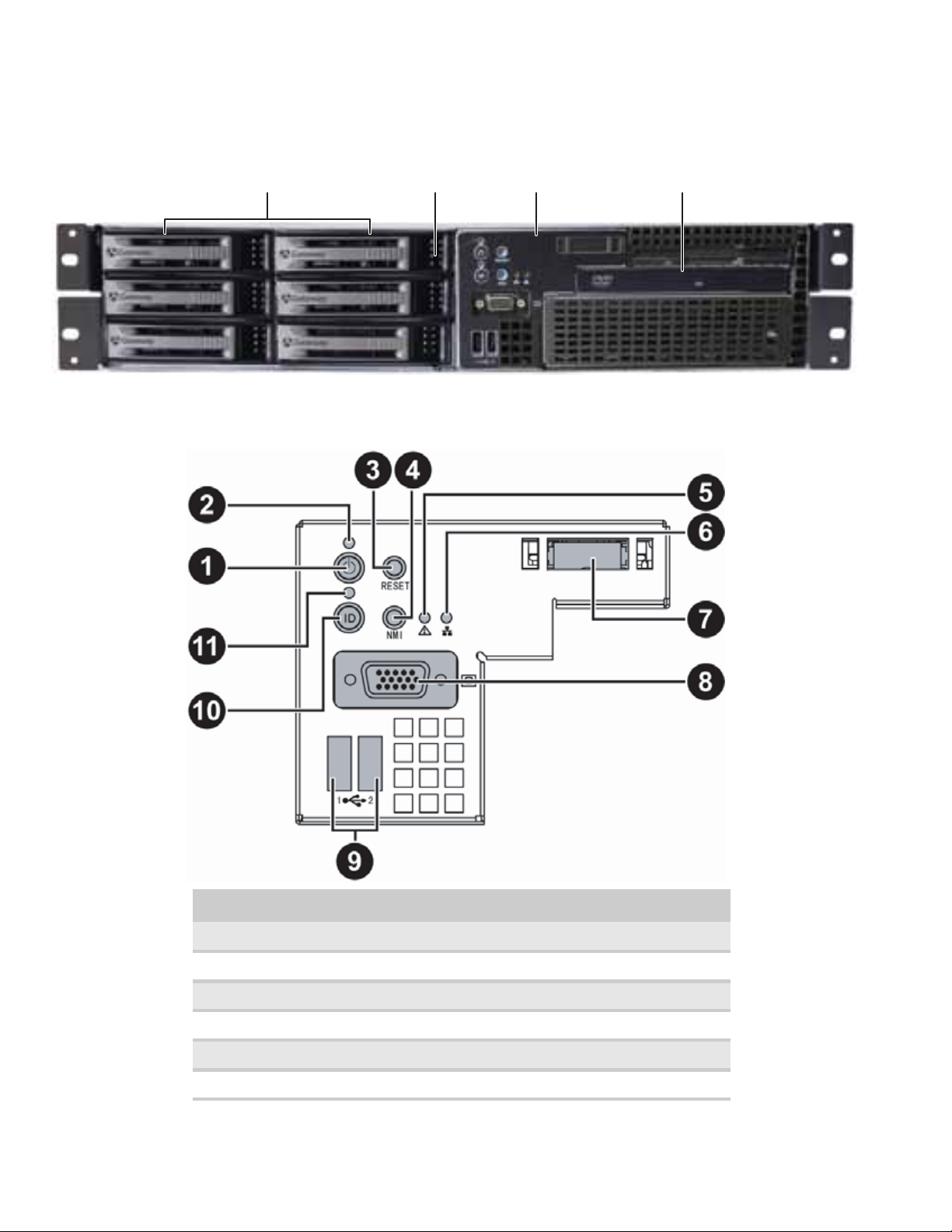
Front
CHAPTER 1: Checking Out Your Gateway Server
Control panel
Hard drives
Hard drive tray LEDs
Control panel
Optical drive
2
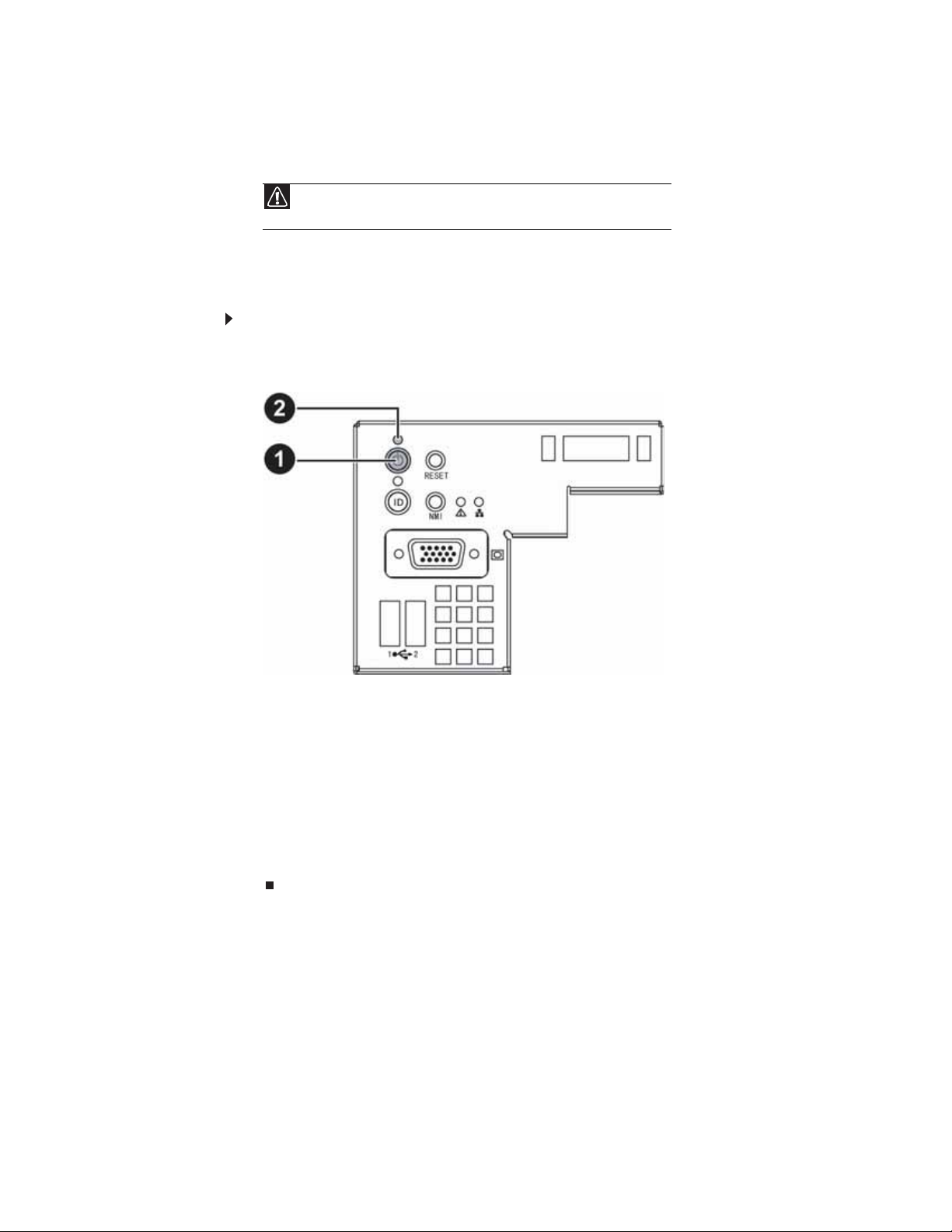
# Feature # Feature
1 Powe r bu t to n 7 SMIL module plug
2 Power LED 8 VGA connector
3 Reset bu tton 9 Dual USB po rts
4 NMI button 10 ID button
5 Syste m fau l t L ED 11 ID LED
6NIC status LED
Page 9
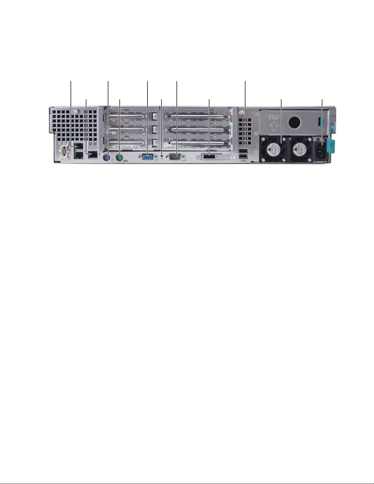
Back
www.gateway.com
Dual NIC conn ectors
Server
management port
PS/2 Keyboard port
PS/2 Mouse port
VGA po rt
ID LED
Serial port
SAS JBOD connector
(optional)
Dual USB por ts
Powe r s up p ly
AC po we r
connector
3
Page 10
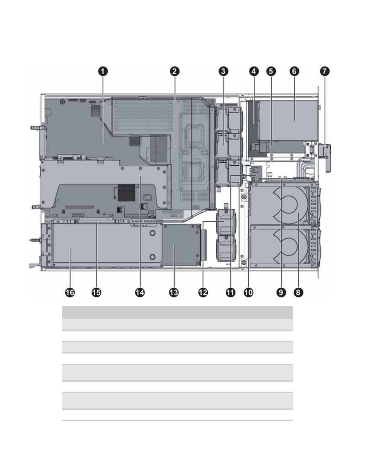
Interior
CHAPTER 1: Checking Out Your Gateway Server
4
# Feature # Feature
1 Syst em bo a rd 9 Control pa nel a dapter ca rd
2 Fan duct 10 SAS/SATA backplane
3 Syst em fa ns 11 Syste m fan s
4 Tape drive (optional) 12 System fans
5 Slimline DVD/CD-RW combo drive or
DVD- RW dr ive
6 Diskette drive (optional) 14 Riser card assembly
7 SMIL module (optional) 15 ROMB battery pack for mezzanine RAID
8 Hard drive bays 16 Power supply
13 RPS power distribution module
card
Page 11
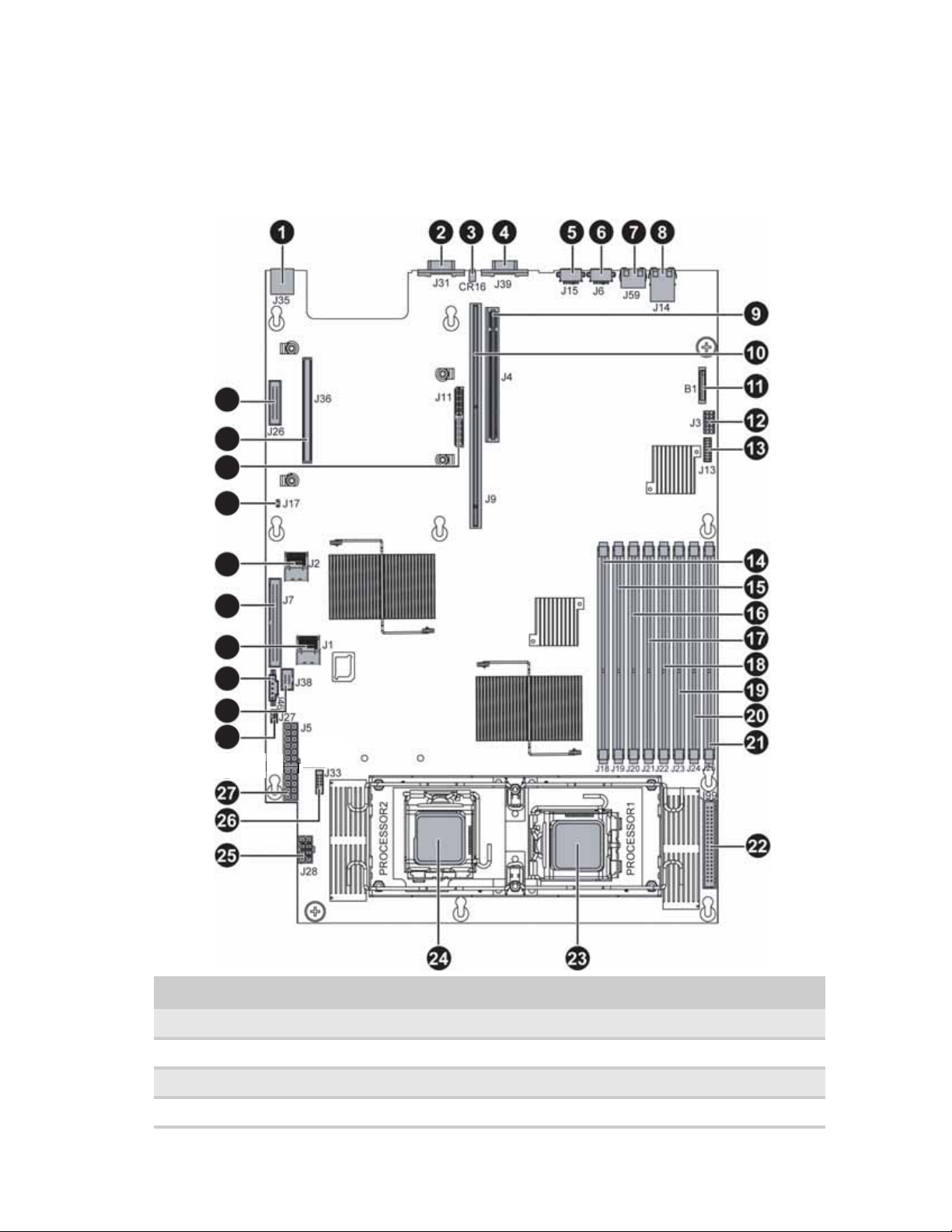
S yst em board
Connectors
37
36
35
34
www.gateway.com
33
32
31
30
29
28
# Feature # Feature
1 Rear dual USB Port ( J35) 20 DIMM7 socket (J24)
2 Serial port (J31) 21 DIMM8 socket (J25)
3 ID LED (CR16) 22 Fan po wer /fa n t ach co n ne ctor ( J9 9)
4 VGA port (J39) 23 Processor 1 (CPU1) socket
5
Page 12

CHAPTER 1: Checking Out Your Gateway Server
# Feature # Feature
5 PS/2 mouse port (J15) 24 Processor 2 (CPU2) socket
6 PS/2 keyboard port (J6) 25 Processor power connector (J28)
7 Server management port (J59) 26 SMIL connector (J33)
8 Dual NIC connector (RJ-45) (J14) 27 Main power connector (J5)
9 PCI-E expansion slot (J4) 28 In ternal USB p ort for USB flo ppy ( J27)
10 PCI-X/PCI-E expansion slot (J9) 29 Control panel USB connector (J38)
11 Battery (B1) 30 Power s up ply I2C connector (J46)
12 System configuration jumper (J3) 31 Mini-SAS connector 1 (J1)
13 Front panel VGA connector ( J13) 32 Control panel IDE connector (J7)
14 DIMM1 socket (J18) 33 Mini-SAS connector 2 (J2)
15 DIMM2 socket (J19) 34 Chassis intrusion connector (J17)
16 DIMM3 Socket (J20) 35 PCI-E mezzanine board connector (J11)
17 DIMM4 socket (J21) 36 PCI-X mezzanine board connector (J36)
18 DIMM5 socket (J22) 37 Floppy connector (J26)
19 DIMM6 socket (J23)
6
Page 13
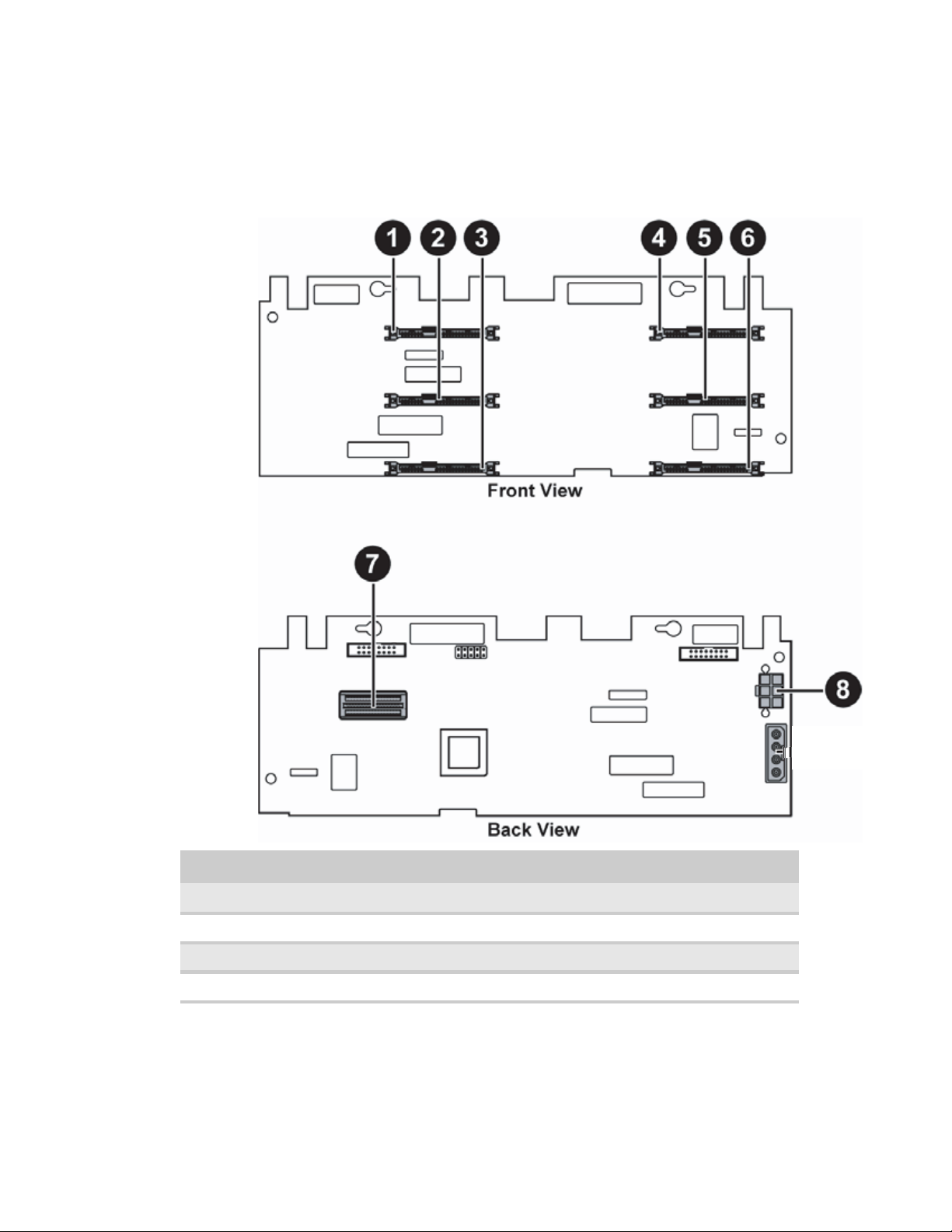
Hot -sw ap backplanes
SAS/SA T A backplane
www.gateway.com
# Feature # Feature
1 SAS/SATA hard drive connector 0 5 SAS/SATA hard drive connector 4
2 SAS/SATA hard drive connector 1 6 SAS/SATA hard drive connector 5
3 SAS/SATA hard drive connector 2 7 Backplane SAS connector
4 SAS/SATA hard drive connector 3 8 Hard drive power connector 1
7
Page 14
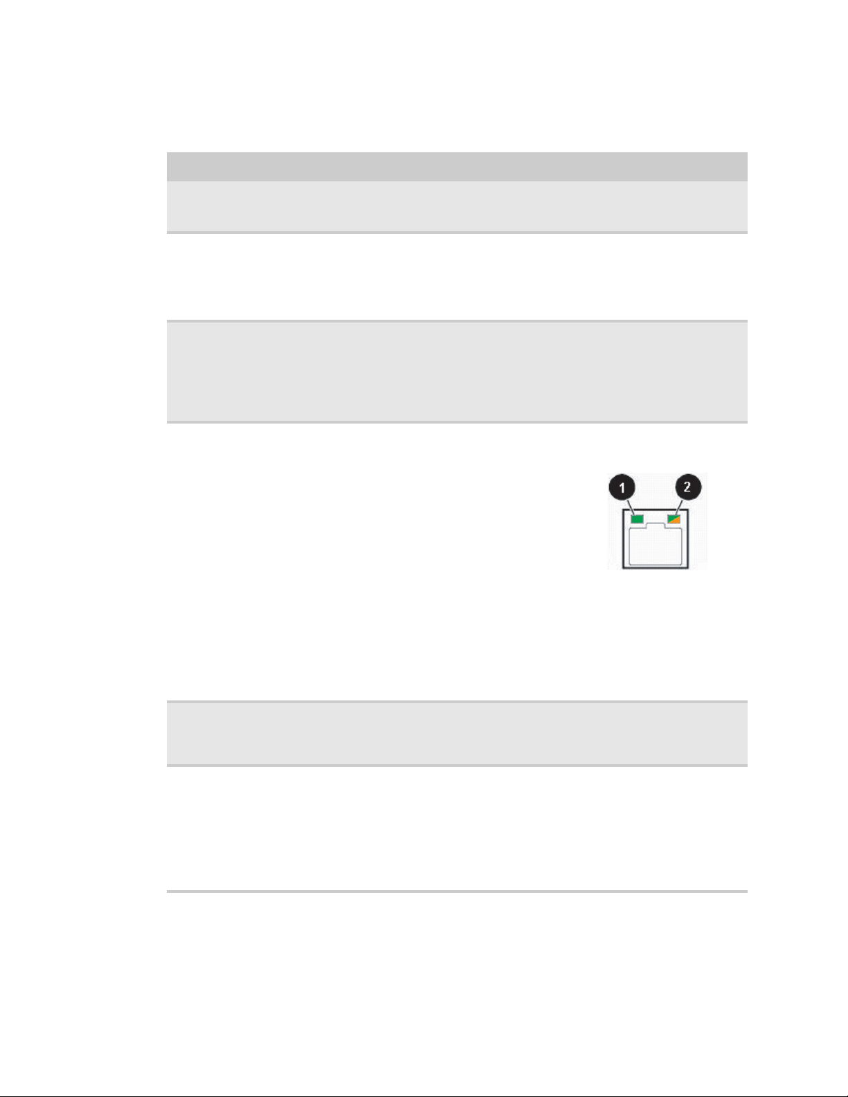
LED inf ormation
See the following table for a description of this server’s LEDs and the information they provide:
LED Name Function Location Color Description
CHAPTER 1: Checking Out Your Gateway Server
ID Aid in server
System Fault Visible fault
Hard drive tray
LEDs
NIC status LEDs Identify NIC states Control panel and
identification
warning
Indicate drive
status and activity
Control panel and
back of system
board
Control panel Red Off = System normal
On each hard drive
tray
back I/O panel
RJ-45 connectors
Yellow
(front)
Blue (back)
Blue or red Blue (On) - Hard drive present
Blue (front)
Green/
Orange
(back)
On = Server identification
enabled
Blinking = Non-critical system
fault
On = Critic al system fault
(system ne eds to be shu t dow n
and serviced)
Blue (Blinking) - Hard drive
activity
Red (On) - Hard drive fault
Red (Blinking) - Hard drive
rebuilding
Off - No hard drive access
Blue (On) - Link
Blue (Blink) - Activity
Off - No link
LED 1 Green (On) - NIC linked
LED 1 Green (Blinking) - NIC 1
Gbps activity
LED 1 (Off) - No link
LED 2 Orange (On) Link speed
1Gbps
LED 2 Green (On) - Link at
100Mbps
LED 2 Green (Off) - Link at
10 Mbps
8
Power LE D Identify t he po wer
state of the system
AC power LED Identif y power
supply fault
Control panel Blue Off = Power is off
Power su pp ly
module
Green or
Orange
Blinking = Power saving state
(S1, S3, or S4)
On = Power is on
Green (On) - Pow er supply good
and receiving power
Orange (On) - Power supply
critical event causing shutdown
Orange (Blinking) - Close to
protection threshold or over
within 15 seconds
Off - Po we r suppl y not r ecei ving
power
Page 15

Get ting Help
In addition to your operating system’s documentation, you can use the following information
resources to help you use your server.
Server Companio n DVD
Use the Server Companion DVD to access file utilities, WindowsServer 2003 drivers, and
documentation for your server and its components. For instructions, see Using Your Ser ver
Compa ni on DV D.
Gatew ay W eb site
Gateway provides a variety of information on its Web site to help you use your server.
Visit the Gateway Web site at support.gateway.com
• Technical documentation and product guides
• Technical tips and support
• Updated hardware drivers
• Order status
• Frequently asked questions (FAQs)
www.gateway.com
for :
T elephone sup port
You can access a wide range of services through your telephone, including customer service,
technical support, and information services. For more information, see “Telephone support” on
page 68.
9
Page 16

CHAPTER 1: Checking Out Your Gateway Server
10
Page 17

CHAPTER 2
Setting Up Your Serv er
• Setting up the hard war e
• Prot ecting f rom po wer sour ce problems
• Mounting your server int o a cabinet
• Starting your serv er
• Setting up the operating sy stem
• Initial hardwar e set tings
11
Page 18
CHAPTER 2: Setting Up Your Server
Set ting up the hard war e
To make sure that your working environment is safe:
• Use a clean, dry, flat, stable surface for your server. Allow at least 6 inches at the back of
the server for cabling and air circulation.
• Use the instructions on your server’s setup poster to set up your hardware.
Caution
Your server comes with 3-wire ACpower cords fitted with the correct plug
style for your region. If this plug does not match the connector on your surge
protector, UP S, or wal l o u tle t, do no t attem pt to m od if y the pl ug i n any way. Use a
surge protector, UPS, or wall outlet that is appropriate for the supplied ACpower
cords.
• Use a grounded (three-prong) surge protector. A surge protector helps protect against AC
power fluctuations. For additional protection from power outages, we recommend that you
use an uninterruptible power supply (UPS).
• Avoid subjecting your server to extreme temperature changes. Do not expose your server
to direct sunlight, heating ducts, or other heat-generating objects. Damage caused by
extreme temperatures is not covered by your warranty. As a general rule, your server is
safest at temperatures that are comfortable for you.
• Keep your server and magnetic media away from equipment that generates magnetic fields,
such as unshielded stereo speakers. Strong magnetic fields can erase data on both diskettes
and hard drives. Even a telephone placed too close to the server may cause interference.
Important
Keep the server boxes and packing material in case you need to ship the
server.
Prot ecting f rom pow er source pr oblems
Surge protectors, line conditioners, and uninterruptible power supplies can help protect your
server against power source problems.
Surge protectors
Caution
High voltages can enter your server through the power cord and the modem and
network connections. Protect your server by using a surge protector. If you have a modem,
use a surge protect or that has t he appropriate type of modem jack. During an electrical storm,
unplug the surge protector and the modem and network cables.
During a power surge, the voltage level of electricity coming into your server can increase to far
above normal levels and cause data loss or server damage. Protect your server and peripheral
devices b y c onnecting them t o a surge pr ot ec t or, which absorbs voltage surge s and prevents them
from reaching your server.
When you purchase a surge protector:
• Make sure that the surge protector meets the appropriate product safety certification for
your locati on, such as Und erwriters La boratories (UL) .
• Check the maximum amount of voltage the protector allows to pass through the line. The
lower the voltag e, the better the p rotection for your server.
• Check the energy absorption (dissipation) rating. The higher the energy absorption rating,
the better the p rotection for your server.
12
Line conditioners
A line conditioner protects your server from the small fluctuations in voltage from an electrical
supply. Most s erv ers can handle this var iation, called line noise, without problems. How ever, some
electrical sources include more line noise than normal. Line noise can also be a problem if your
server is located near, or shares a circuit with, a device that causes electromagnetic interference,
such as a television or a motor.
Page 19
www.gateway.com
Some surge protectors and uninterruptible power supplies include simple line-conditioning
capabilities.
Uninterruptible power supplies
Use an uninterruptible power supply (UPS) to protect your server from data loss during a total
power failure . A UPS us e s a batt ery to k eep y our server r unning temporar ily dur ing a power f ailur e
and lets you save your work and shut down your server. You cannot run your server for an
extended period of time while using only the UPS. To buy a UPS, visit www.gateway.com
Mounting your s erver int o a cabinet
Caution
Before attaching cabinet accessories, make sure that the server is turned off and all
power cords are unplugged.
The fixed-rail cabinet mounting hardw are inc luded with y our server should be used with standar d
4-post cabinets that have front and back vertical posts. If your cabinet is a different type, obtain
mounting hardware from the cabinet manufacturer.
Caution
The ca bin et mus t p rovid e s uffi cie nt ai rfl ow to the fro nt of the se rve r to ma in tai n
correct cooling.
.
The fixed-rail rackmount kit contents:
• Front ser ver rai ls (2 )
• Back server rails (2)
• Faste n er p a ck (1)
• Lock in g s crews (4 )
• Mounting nuts (4)
• Mounting screws (4)
If you ordered the optional tooless-rail kit for your server, refer to the instructions included in the
kit.
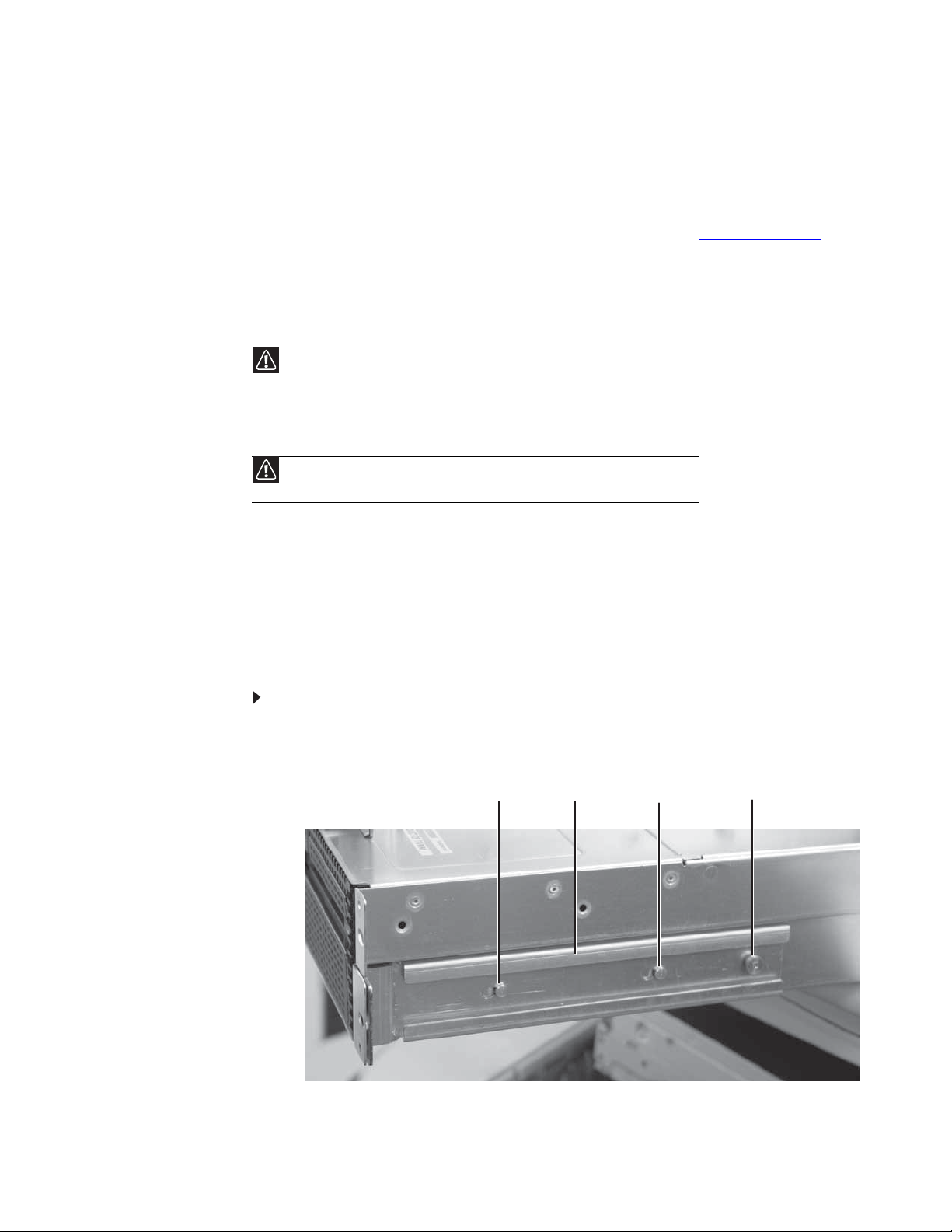
To mount your server in a cabinet:
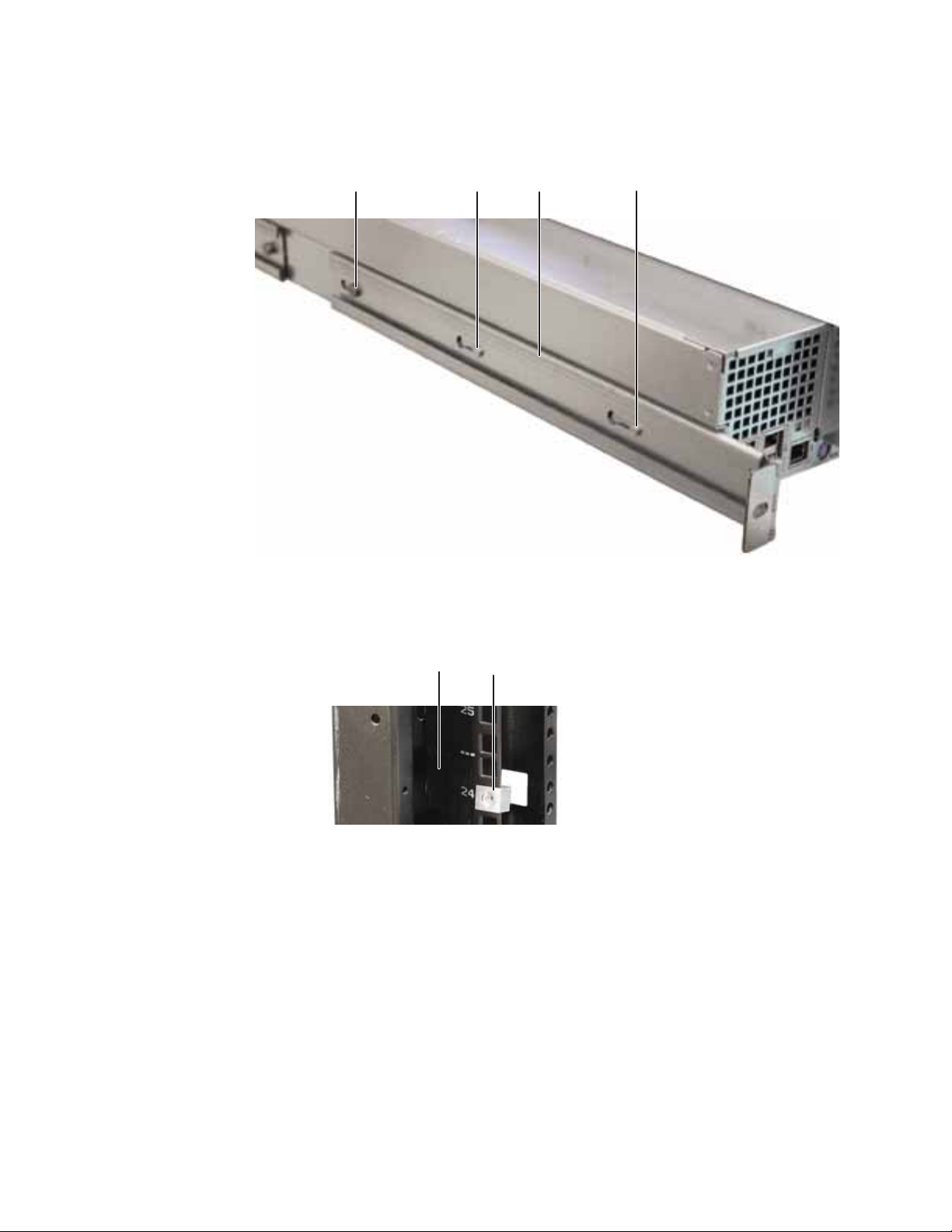
1 Align the slots in the front server rails with the studs on the side of the server, then engage
the slots with the studs and slide the rails forward until they stop.
Stud
Front server rail
(installed)
Stud
Locking screw (installed)
2 Align the locking screw holes in the rails with the threaded screw holes in the server, then
install one locking screw through the each front server rail.
13
Page 20
CHAPTER 2: Setting Up Your Server
3 Align the slots in the back server rails with the studs on the side of the server, then engage
the slots with the studs and slide the rail forward until it stops.
Back server rail
Locking screw (installed)
Stud
(installed)
Stud
4 Align the locking screw holes in the rails with the threaded screw holes in the server, then
install one locking screw through the each back server rail.
5 Attach one mounting nut to each of the two front cabinet posts where you plan to install
the server.
Front cabi net post
Mounting nut
14
Page 21
www.gateway.com
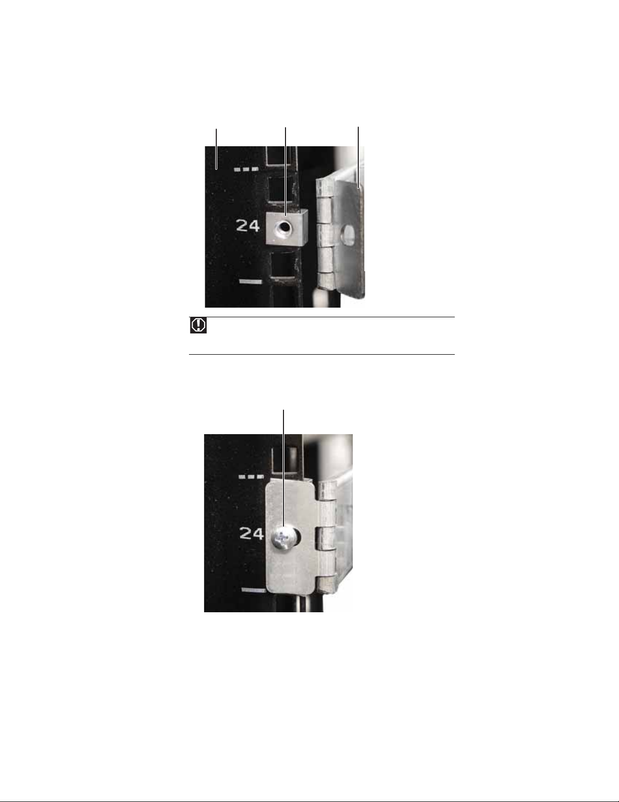
6 Attach one mounting nut to each of the two back cabinet posts where you plan to install
the server.
Hinged back rail
Back cabinet post
Mounti ng nut
Warning
You must support the server while installing or removing the front and back
mounting screws. If the server is not supp orted, damage t o the server or i nju ry may
result.
mounting bracket
7 Hold the server in place in the cabinet and swing the hinged back rail mounting brackets
into alignment with the mounting nuts, then secure the back in place with two mounting
screws (one on ea ch side ) .
Mounting screw
15
Page 22
CHAPTER 2: Setting Up Your Server
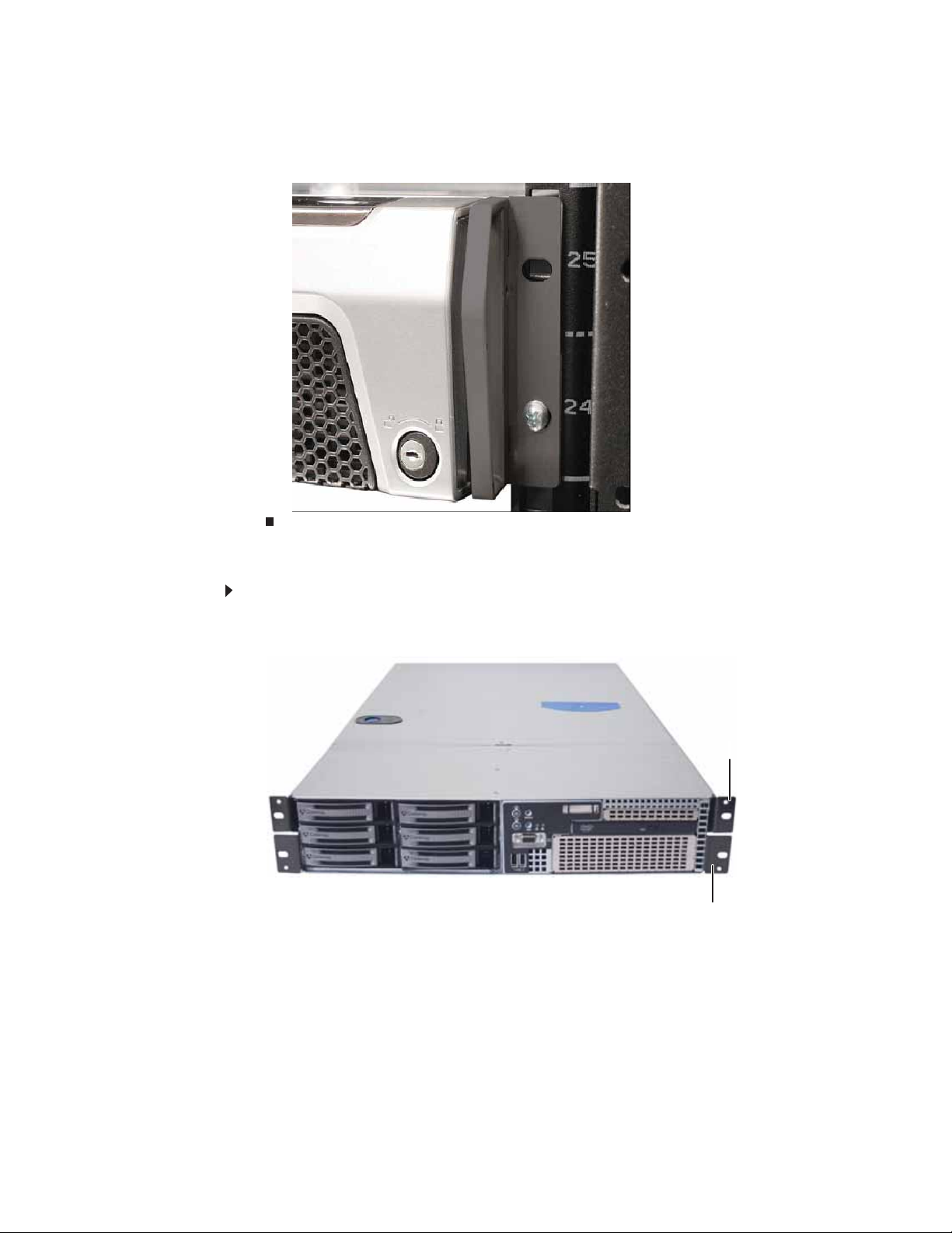
8 Align the mounting screw holes in the server handles with the front mounting nuts, then
secure the front in place with two mo untin g screws (one o n each s ide) .
Installing the bez el
To install the bezel:
1 With the server pulled out from the cabinet, align the holes in the handle with the small
holes in the mounting brackets on the front side of the server.
2 Attach the handles to the sides of the server with two mounting screws on each side.
Mounting bracket
Mounting bracket
16
Page 23
www.gateway.com
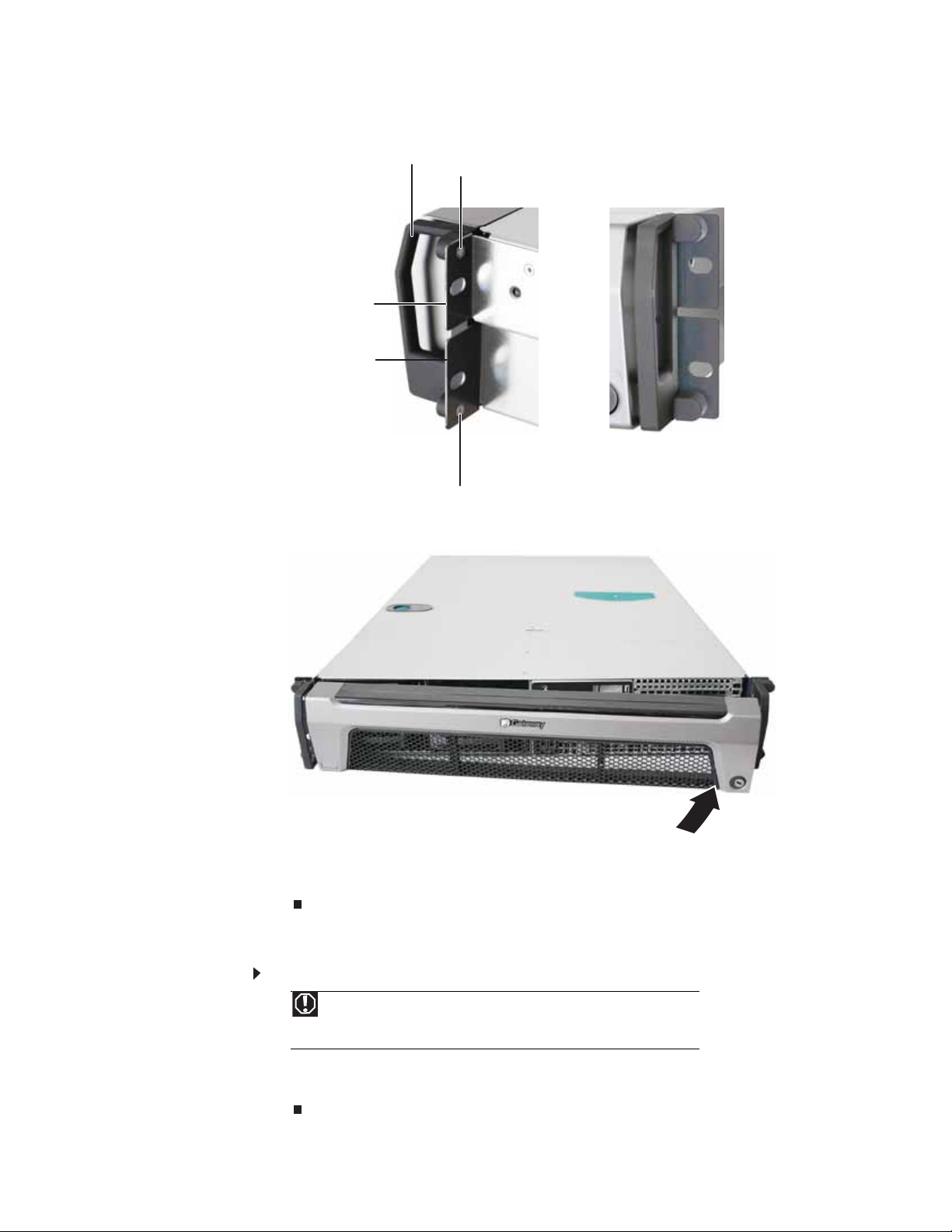
Ba ck vi ew
Handle
Mounting screw
Mounting bracket
Mounting bracket
Mounti ng screw
Front view
3 Remove the bezel lock key s from the inside of the bezel, then insert the left side of the bezel
into the left handle and swing the right side of the bezel in until it snaps into place.
4 When the bezel is in place, lock the bezel by inserting the key into the lock in the lower right
corner of the bezel and turning it clockwise until it stops (approximately ¼ turn).
5 Put the key in a safe p lac e.
Remo v ing the se rver f rom a ca binet
To remove the server from a cabinet:
Warning
Screws are required to support the front of the server. You must support the
server while removing the front screws and while sliding the server off the cabinet
rails. If the server is not supported, damage to the server or injury may result.
1 Remove the thumbscrews through the handles that hold the server in the cabinet.
2 While supporting the server, slide the server out from the cabinet.
17
Page 24
CHAPTER 2: Setting Up Your Server
Starting y our server
Before you start your server for the first time:
Caution
When you connec t periphe ral de vices t o t he server, make sure th at your server
and devices are turned off and the power cords are unplugged.
• Make sure that the server and monitor are plugged into a power outlet or surge protector
and that the surge protector (if you are using one) is turned on.
• Make sure that al l ca bles are co nne cted securely to the co rrect port s a nd ja cks on the back
of the server.
To start the server:
1 Turn on any peripheral devices connected to the server.
2 Press the powe r b utto n (1) . Th e Powe r L ED (2 ) li gh ts.
If nothing happens when you press the power button:
• Make sure that the power cable(s) is plugged in securely and that your surge protector
(if you are using one) is plugged in and turned on.
• Make s ure tha t th e m on ito r i s co nn ecte d to the ser ver, pl ug ged in to th e p owe r ou tl et
or surge protec tor, and turned on. You may also need to adju st the monitor’ s brightnes s
and contrast controls.
• If you cannot find the cau se of th e power l oss, contac t Gat ew ay C ust omer Care . For mor e
information, see “Getting Help” on page9.
3 The first time you turn on the server, any pre-installed operating syste m may begin asking
you for configuration settings. See your operating system’s documentation for instructions
on configuring advanced settings for your specific network.
Understanding the po wer-on self -te st
When you turn on your server, the power-on self-test (POST) routine checks the server memory
and components. If POS T finds any problems, the server displays err o r me ssages. W rite down any
error m e ssages th a t yo u see, then see “Error messages” on page69 and “Beep codes” on page 74
for troubleshooting information.
18
Page 25

www.gateway.com
T urning of f y our serv er
Every time you turn off your server, first shut down the operating system. You may lose data if
you do not follow the correct procedure.
To turn off the server:
Caution
The power butt on on t he serv er does not tu rn off server A Cpower. To remove
ACpower from the server, you must unplug t he ACpower cords from the wall o utle t
or power source. The power cords are cons ide red the disco nnect dev i ce to the main
(AC) power.
1 See the operating system’s documentation or online help for instructions on shutting down
the operating system. Whenev er pos sible , y ou should use the operating sy st em’s shut down
procedure instead of pressing the power button.
2 If your server did not turn off automatically, press the power button.
- OR Press the reset bu tton to re set t he ser ver.
Set ting up the operating s yst em
If you ordered your server with the operating system already installed by Gateway, in most cases
it is completely installed and the basic settings are already configured. The Windows Small Business
Server operating system may require additional installation, depending on the version you
ordered. See your operating system’s documentation for instructions on completing the
installation or configuring advanced settings for your specific network.
If you are installing an operating system because it was not already installed by Gateway, see the
appropriate instal lation gui de for instructions.
Initial hard ware s ettings
Y our server comes fr om the manufact urer with the cor rect initial hardw are se ttings to operat e your
server as configured. However, at some point you might want to change settings to reflect a tasking
change, a change in security requirements, or the addition of new resources to your server.
General hardware settings can be changed by using the BIOS Setup utility. For information on the
BIOS Setup utility, see “Using the BIOS Setup Utility” on page59. For information on BIOS settings,
see “ BIOS Settings” on p age 93.
19
Page 26

CHAPTER 2: Setting Up Your Server
20
Page 27

CHAPTER 3
Maintaining Y our Server
• Caring f or your s erver
• Preparing for s yst em recov ery
• Sy stem administration
• Identifying y our server
• Updating the baseboar d management controller
firmware
• Using your Server Companion DVD
21
Page 28

CHAPTER 3: Maintaining Your Server
Caring f or y our server
To extend the life of your server:
• Be careful not to bump or drop your server.
• When transporting your server, we recommend that you put it in the original packaging
materials.
• Keep your server and magnetic media away from equipment that generates magnetic fields,
such as unshielded speakers.
• Avoid subjecting y our server t o ex treme temperatur es. Do not expo se your se rver to heating
ducts or other heat-generating objects. Damage caused by extreme temperatures is not
covered by your warranty. As a gen eral ru le, your ser ver is safest at tem pera tures that are
comfortable for you.
• Keep al l l iqu id s away fro m yo ur s er ver. Whe n sp ill ed on to se rver co mp one nt s, a lm ost any
liquid can result in extremely expensive repairs that are not covered under your warranty.
• Avoid dusty or dirty work environments. Dust and dirt can clog the internal mechanisms
and can cause the server to overheat.
Cleaning y our serv er
Keeping your server clean and the vents free from dust helps keep your server performing at its
best. Your server cleaning kit could include:
• A soft, lint-free cloth
• Glass cleaner
• An aerosol can of air with a narrow, straw-like extension
• Isopropyl alcohol
• Cotton swabs
• A tape drive cleaning cartridge (if a tape drive is installed)
• A CD drive cleaning kit
Cleaning tips
Warning
When you shut down your server, the power turns off, but some electrical
current still flow s through your serv er. To avoid possible injury from elec trical sh ock,
unplug the power cord and all other cables connected to the server.
• Always turn off your server and other peripheral devices before cleaning any components.
• Use a damp, lint-free cloth to clean your server and other parts of your server system. Do
not use abrasive or solvent cleaners because they can damage the finish on components.
• Keep the cooling vents free of dust. With your server turned off and unplugged, brush the
dust away from the vents with a damp cloth, but be careful not to drip any water into the
vents.
Cleaning the k e yboard
Y ou should clean t he k e y boar d occa sionall y b y usi ng an aer osol can of air wit h a nar ro w , str aw -lik e
extension to remove dust and lint trapped under the keys.
If you spill liquid on the keyboard, turn off your server and turn the keyboard upside down to let
the liquid drain. Let the ke y board dry complet ely befor e trying t o use it again. If the ke y board does
not work after it dries, you ma y need to r eplaceit. K eyboard damage resulting fr om spilled liquids
is not covered by your warranty.
22
Page 29

www.gateway.com
Cleaning the scre en
Caution
The computer screen is made of specia lly coated glass and can be scratched or
damaged by abrasive or ammonia-based glass cleaners.
If your computer screen is a flat panel display, use only a damp, soft cloth to clean it. Never spray
water d ire ctly on to the scree n.
- OR If your computer screen is not a flat panel display, use a soft cloth dampened with glass cleaner
to clean the screen. Never spray cleaner directly onto the screen.
Cleaning the tape driv e
If you use a tape dri v e to back up your file s, regular maint enance w ill lengthen the life of the driv e .
To maintain the drive’s reliability:
• Clean the drive monthly with the cleaning cartridge included with thedrive.
• Remove the tape from the drive whenever the drive is not in use.
Preparing f or s yst em reco very
If your system files are corrupted, you may not be able to start the server from the hard drive.
Startup diskettes are diskettes that let you start the server and attempt to fix the problem. See
your operating system’s documentation or online help for instructions on creating startup
diskettes.
Some operating systems also let you create an emergency repair diskette to back up critical
operating system files. See your operating system’s documentation or online help for instructions
on creating and using an emergency repair diskette.
Recor ding the BIO S configur ation
To help keep track of your custom changes to BIOS settings and to prepare for system recovery,
you should record your BIOS configuration after you have your server set up and working.
To record your BIOS configuration:
1 Print the appendix for “BIOS Settings” on page93.
2 Restart your server, then press F2 at any time after you see the LEDs on your keyboard
flash or turn off. The BIOS Setup utility opens.
3 Record the BIOS settings on your printout.
S yst em administr ation
Gatew a y Sy stems Manager
Gatew ay Sy stems Manager (GSM) lets you manage multiple computers on a Window s network fr om
a single window, t hen implement commands and policies ac ross the netw ork w ith a single action.
With Gateway Systems Manager, you can run system management tasks which are triggered by
certain events or conditions.
For more informa tion, refer to the Gateway Baseboard Management Controller (BMC) User Guide
at http://support.gateway.com/support/default.asp#
can also find additional information in the program’s online help.
(by selecting this server from the list). You
23
Page 30
Server sec urity
CHAPTER 3: Maintaining Your Server
Locking the server
To lock the server:
1 Remove the bez el lock k e y s f r om the inside of the bezel, t hen snap on the bezel. T he handles
must be installed for the bezel to snap on. For instructions, see “Installing the bezel” on
page 16.
2 Insert the key into the lock and rotate it ¼ turn clockwise. To unlock it, rotate the key ¼
turn counter-clockwise.
Using BIOS secur ity passw ords
To prevent unauthorized use of the server, you can set server startup passwords. Set an
administrator password to prevent unauthorized access to the BIOS Setup utility.
To set the BIOS security passwords:
1 Restart your server, then press F2 at any time after you see the LEDs on your keyboard
flash or turn off. The BIOS Setup utility opens.
2 Select the Security menu.
3 Select Change Administrator Password.
4 Type the password and press ENTER, then type it again and press ENTER.
5 Save your changes and close the BIOS Setup utility.
To remove a BIOS security password:
Tip
Passwords can also be cleared using jumpers on the system board. For
instructions, see “Resetting BIOS passwords” on page63.
1 Restart your server, then press F2 at any time after you see the LEDs on your keyboard
flash or turn off. The BIOS Setup utility opens.
2 Select the Security menu, then select the password to remove.
3 Enter the curre nt password, then press E NTER.
4 For the new password, leave the password field blank, then press ENTER. The passwo rd i s
removed.
Identifying y our serv er
While you are working on a cabinet that contains several slim servers, it can be difficult to keep
track of which server or servers you are currently working on. The SystemID indicator is a yellow
(front) and blue (back) LED that you can turn on to help you locate the correct server. For the
System ID indicator to turn on, the server does not need to be turned on, but it does need to be
plugged in.
To turn on the System ID ind icator:
1 Press the ID button on the control panel of the server. The yellow (front) and blue (back) ID
LED indicators turn on. For the location of these LEDs, see “LED information” on page8 .
2 To turn off the in di cato r, press th e Syste m ID butto n.
24
Page 31

www.gateway.com
Updating the ba seboard man agement controller firmware
The baseboard management controller (BMC) performs several system management functions
such as:
• Monitoring server components (FRU) and sensor data records (SDR) (the information
provided depends on the option selected)
• Managing non-volatile storage for the system event log and sensor data records
• Interfacing with the emergency management port to send alerts and interact with remote
management systems
• Fault resilient booting (the extent depends on the option selected)
Y ou should update the BMC firm war e when Gate w ay C ust omer Care has instr uct ed you to update it.
To u p d at e t he B M C fi r m wa r e:
1 Down loa d th e B MC fir mware zip fi le from support.gateway.com.
2 Read the release notes for the firmware update.
3 Follow the instructions on the Web site or in the readme.txt file in the downloaded zip file
to update the firmware.
4 When th e BM C u pd ate i s c om pl ete, reb oo t yo ur s er ver.
Using y our Server C ompanion DVD
You can use your Server Compa nion D VD to :
• Install hardware drivers
• Install programs
• View ser ver docu men tat ion
Server C ompanion D VD contents
The Server Comp anio n D VD is a tool you can use to help maintain your server. The DVD contains:
• Computer and component documentation
• Drivers and utilities for servers running Windows 2003 Server
Vie wing doc uments
The DVD contains documents for your server and for some optional components. You can view
the documents with the Acrobat® Reader® version 4.0 and above.
To v i ew d o cu m e n ts :
1 Insert the Server Companion DVD into the DVD drive on a computer running the Windows
operating system. The Gateway Application and Driver Recovery window opens.
- OR If the window does not open, run the file Runmenu.exe on the DVD.
2 Click Documentation. The server document list opens.
3 Click the title of the document you want to view. The document opens.
4 To access files manually, open the Docs\Manuals folder on the Server Compa nion DVD.
25
Page 32

CHAPTER 3: Maintaining Your Server
To i n s ta l l A c ro b a t R e ad e r 7:
• Click the link for Acrobat on the Documentation page.
- OR Run Docs\Reader\app21279\Setup.exe fro m t he Server Compa nion DVD.
Installing dri vers and pr ograms
Y ou can install driv ers and programs direc tly onto t he server b y using the Server Companion
DVD. You can also extract drivers onto diskette from the DVD at any Windows workstation.
Important
The Server Companion DVD’s Gateway Application and Driver Recovery utility works
only in Windows operating systems.
To install drivers and programs at the server:
1 Insert the Server Companion DVD into your server’s DVD drive. The Gateway Applic at ion and
Driver Recovery window opens.
- OR If the window does not open automatically, run the file Runmenu.exe on the DVD.
A list of programs and drivers that you can install appears in the Drivers and Application
Recovery li st.
2 Click the program or driver you want to install, then click Install. Follow any on-screen
instructions.
To access the files m anually, open th e Drivers folder on the Server Compan ion DVD, then
open the appropriate subfolder.
To extract drivers and programs to diskettes:
1 Insert the Server Companion DVD into your server’s DVD drive. The Gateway Applic at ion and
Driver Recovery window opens.
- OR If the window does not open automatically, run the file Runmenu.exe on the DVD.
2 Click Extract Drivers.
3 Click your server model and server operating system at the right of the window, then click
Search. A list of programs and drivers that you can create diskettes for appears in the
Drivers and Application Recovery list.
4 Click the program or driver you want to extract, then click Extract. Follow any on-screen
instructions.
To access the files m anually, open th e Drivers folder on the Server Compan ion DVD, then
open the appropriate subfolder.
26
Page 33

www.gateway.com
Booting fr om the Serv er C ompanion D VD
By booting from the Server Companion DVD, you can repair applications and drivers, or exit to
the command prompt.
Important
Although the Server Companion DVD is bootable, it does not include network
operating system files and is not intended to restore your operating system.
To boot from this DVD:
1 With your server turned on, insert the Server Companio n DVD i nto th e DVD drive.
2 Restart your server. A message appear s asking you to select an op tion.
3 Press any key to boot from the DVD. The Gateway Options Main Menu appears.
4 Follow any on-screen instructions.
Y ou can use t he options in t his menu to r ef ormat y our hard driv e, creat e mas s-st orage dr iv er
disks, or reload selected applications.
27
Page 34

CHAPTER 3: Maintaining Your Server
28
Page 35

CHAPTER 4
Installing Components
• Preparing to install components
• Prev enting static electric ity discharge
• Opening the server case
• Closing the server case
• Installing and remov ing driv es
• Installing memory
• Installing and remov ing PCI e xpansion cards
• Replacing system fans
• Replacing or adding a p roces sor
• Replacing a po wer supply module
• Replac ing the RPS po wer distribut ion module
• Replacing t he hot-s wap bac kplane
• Installing and remov ing the R OMB battery pack f or
the mezzanine RAID card
• Installing and remov ing an optional mezzanine
board
• Replacing the CMOS battery
• Replacing t he control panel adapt er card
• Replac ing t he s yst em boar d
29
Page 36

CHAPTER 4: Installing Components
Preparing t o install components
Selecting a place to work
Work on your server in an area that:
• Is clean (avoid dusty areas).
• Is a low-static environment (avoid carpeted areas).
• Has a stable surface on which to set your server.
• Has enough room to place all of your server parts.
• Is near a grounded outlet so you can test your server after installation.
• Is near a telephone (in case you need help from Gateway Customer Care). The telephone
must be directly connected to a telephone jack and cannot be connected to your server.
Gathering t he tools y ou need
Tip
Blue latches, thumbscrews, or connectors indicate tool-less components.
Green latches and connectors indicate hot-swappable components.
Some tools and supplies that you may need to work on your server are:
• A note bo ok to t ake n otes
• A Phillips screwdriver
• A small flat-blade screwdriver
• Small containers to store various types of screws
• A grounding wrist strap (available at most electronic stores)
Getting Help
If you hav e questions about perf or ming an y of the s e procedure s, contac t Gat ewa y Customer Care .
For m ore in form ati on , se e “Getting Help” on page 9.
Pre v enting static electric ity dischar ge
Warning
To avoid exposure to dangerous electrical voltages and moving parts, turn off your
server and unplug the power cords and modem cable before opening the server case.
The components inside your server are extremely sensitive to static electricity, also known as
electrosta tic di scharge (ESD) .
Caution
ESD can permanently damage electrostatic discharge-sensitive components in the
server . Pre v ent ESD damage by following ESD guidelines ev ery time you open the server ca se.
Before working with server components, follow these guidelines:
Warning
To prevent risk of electric shock, do not insert any object into the vent holes
of the power supply.
• Turn off the server, then unplug the power cords and all other cables.
• Press the power button to drain any residual power from the server.
• Wear a grounding wrist strap (available at most electronics stores) and attach it to a bare
metal part of the server. You can also touch a bare metal surface on the back of the server
with your fing er.
• Avoid static-causing surfaces such as carpeted floors, plastic, and packing foam.
• Avoid working on the server when your work area is extremely humid.
30
Page 37

www.gateway.com
• Remove components from their antistatic bags only when you are ready to use them. Do
not lay components on the outside of antistatic bags because only the inside of the bags
provide electrostatic protection.
• Always hold expansion cards by their edges or their metal mounting brackets. Avoid
touching the edge connectors and components on the cards. Never slide expansion cards
or components over any surface.
Opening the serv er case
Because the components inside your server are extremely sensitive to static electricity, make sure
that you follow the instructions at the beginning of this chapter to avoid static electricity damage.
To open the server:
Warning
This server may have tw o powe r co rds. T o disconnect internal ACpower, you
must unplug both power cords.
1 Follow the instructions in “Preventing static electricity discharge” on page 30. Make sure
that you turn off the server, then unplug the power cord(s) and all other cables connected
to the server.
2 If the bezel is installed, unlock it, then pull it off.
Warning
Screws are required to support the front of the server when using the
standard cabin et ra ils. You must support the se rver while removing t he front screws
and while sliding the server off the cabinet rails. If the server is not supported,
damage to the server or injury may result.
3 If the server is mounted in a cabinet, remove the server from the cabinet. For instructions,
see “Removing the server from a cabinet” on page17.
4 Place the server on a stable, non-skid surface.
5 Remove the sc r e w (1) at the f ront of the t op co v er, then press and hold the release button (2).
Important
The hard drive carriers shown in these illustrations may look different than
the actual hard drive carriers in your server.
6 Slide the top cover (3) toward the back of the case, then lift it off the case.
Caution
For correct cooling and air f low, alw ay s reinstal l the t op cove rs befor e you turn
on the server. Operating the server without the covers in place will cause the server
to ove r h ea t .
31
Page 38

CHAPTER 4: Installing Components
Closing the server case
To close the server ca se:
1 Make sure that all of the internal cables are arranged inside the case so they will not be
pinched when you close the case.
2 Place the top cover (1) on the server, then slide it forward until it clicks into place.
Important
The hard drive carriers shown in these illustrations may look different than
the actual hard drive carriers in your server.
3 Replace the screw (2) to hold the top cover in place.
4 Reconnect the power cord(s) and all other cables.
32
Page 39

www.gateway.com
Installing and remo ving dri ve s
Y our server’ s basic configuration includes one optical driv e and as man y as six SAS/S ATA hot-sw ap
hard drives. An optional tape backup drive and an optional diskette drive can also be added.
As you prepare to install drives, remember:
• Before you install a drive, see the drive’s documentation for information on configuring the
drive, setting drive jumpers, and attaching cables.
• You may need to configure the drives you install using the BIOS Setup utility. Restart your
server, then press F2 at any time after you see the LEDs on your keyboard flash or turn off.
Remo ving and installing an optical dr ive
To remove and install an optical drive:
Caution
The optical d riv e i s not hot - swa ppable . B ef or e instal ling or rem ov ing t he dri v e ,
make sure that power is turned off and the power cord is unplugged.
1 Follow the instructions in “Preventing static electricity discharge” on page 30. Make sure
that you turn off the server, then unplug the power cord(s) and all other cables connected
to the server.
2 Unlock the bezel (if necessary) and remove it by pulling it from the chassis.
3 Follow the instructions in “Opening the server case” on page31.
4 Remove the large fan cage by following the instructions in “Replacing system fans” on
page 44.
5 Disconnect the 44-pin optical drive cable from the optical drive interface board.
6 Loosen the thumbscrew (1) holding the media cage in the chassis, then push the
assembly(2 ) out the front of the chassis.
33
Page 40

CHAPTER 4: Installing Components
7 Lift the locking tab (3) on the back of the optical drive tray, then push the optical drive (4)
and tray out of the bay.
8 Lift the optical drive (5), then pull it from the tray (6).
34
9 Unscrew the two screws (5) holding the optical drive interface board on the back of the
optical drive, then remove the interface board.
10 Using the two screws you just removed, attach the optical drive interface board to the back
of the new optical drive.
11 Align the optical drive with the two clips on the left side of the optical drive tray, then press
the optical drive into place in the tray.
12 Inse rt the optical drive tray into the bay in the media cage until it clicks into place.
13 Inse rt the media cage into the assembly bay in the chassis.
Page 41

www.gateway.com
14 Secure the assembly by tightening the thumbscrew you previously loosened.
15 Attach the 44-pin optical drive cable to the back of the optical drive interface board.
16 Reinstall the large fan cage by following the instructions in “Replacing system fans” on
page 44.
17 Follow the instructions in “Closing the server case” on p age 32.
18 Reinstall the bezel, if required, by snapping it into place on the front of the chassis.
19 Reconnect all power cords and peripheral device cables, then turn on the server.
Remo ving and in stalling a tape dri v e
To remove and install a tape drive:
Caution
The tape drive is not hot-swappable. Before installing or removing the drive,
make sure that power is turned off and the power cord(s) is unplugged.
1 Follow the instructions in “Preventing static electricity discharge” on page 30. Make sure
that you turn off the server, then unplug the power cord(s) and all other cables connected
to the server.
2 Unlock the bezel (if necessary) and remove it by pulling it from the chassis.
3 Follow the instructions in “Opening the server case” on page31.
4 Remove the large fan cage by following the instructions in “Replacing system fans” on
page 44.
5 Disconnect the data and power cables from the tape drive.
6 Loosen the thumbscrew (1) holding the media cage in the chassis, then push the
assembly(2 ) out the front of the chassis.
35
Page 42

CHAPTER 4: Installing Components
7 Lift the locking tab (3) on the back of the tape drive tray, then push the tape drive (4) and
tape drive bracket out of the tray.
8 Unscrew th e four mounting screws (5) holding the tape drive in the tape drive brac ket, then
lift the tape drive out of the bracket.
9 Put the new tape drive into the drive bracket and secure with the four screws you removed
previously (if you are installing a new tape drive, the screws and bracket are included with
the tape drive installation kit).
10 Push the new tape drive and drive bracket into the tape drive tray, then push down the
locking tab.
11 Insert the media cage into the assembly bay in the chassis.
12 Se cure the assembly by tightening the thumbscrew you previously loosened.
13 Connect the data and power cables to the back of the tape drive.
14 Reinstall the large fan cage by following the instructions in “Replacing system fans” on
page 44.
15 Follow the instructions in “Closing the ser ver case” on page 32.
16 Reinstall the bezel, if required, by snapping it into place on the front of the chassis.
17 Reconnect all power cords and peripheral device cables, then turn on the server.
36
Page 43

www.gateway.com
Remo ving and in stalling a hard driv e
Important
Gateway tests and verifies the operation and compatibility of the drives it sells.
Especially in a hot-swap or mission-critical environment, additional or replacement drives
must conform to Gateway standards.
Use this procedure t o add or replace a hard dri v e in a hot - swap bay . Your server supports as many
as six 1-inch high, 3.5-inch hot-swap SATA and SATA II hard drives or six 1-inch high, 3.5-inch
hot-swap SAS hard drives. You can purchase additional drives through your Gateway Sales or
Customer Care representative.
To remove and install a hot-swap hard drive:
Caution
Before you remove a failed drive, use the appropriate software and utilities
installed on the server to stop all activity on the failed drive. Instructions for using
the softw are are pr ov ided b y the softw are manu fac ture r . F ailur e to do so may dest ro y
the da ta on the d rive.
1 Unlock the bezel (if necessary) and remove it by pulling it from the chassis.
2 Put your finger in the drive release lever and pull out. The drive release lever opens.
3 Pull the drive carrier straight out of the server.
37
Page 44

CHAPTER 4: Installing Components
4 If you are replacing a hard drive, remove the four screws that secure the old hard drive to
the drive tray, then remove t he drive from the tray . I f you are installin g a new drive, r e move
the dummy hard drive from the drive tray.
5 Using the four screws you removed, install the new hard drive into the drive tray.
6 Make sure that the tray’s release lever is open, then slide the new drive fully into the empty
hot-swap drive bay.
7 Push the lever back into place to secure the hard drive in the bay.
8 Reinstall the bezel, if required, by snapping it into place on the front of the chassis.
Remo ving and in stalling a disk et te dr iv e
To remove and install a diskette drive:
Caution
The diskette drive is not hot-swappable. Before installing or removing the
drive, make sure that power is turned off and the power cord(s) is unplugged.
1 Follow the instructions in “Preventing static electricity discharge” on page 30. Make sure
that you turn off the server, then unplug the power cord(s) and all other cables connected
to the server.
2 Unlock the bezel (if necessary) and remove it by pulling it from the chassis.
3 Follow the instructions in “Opening the server case” on page31.
4 Disconnect the USB cable from the diskette drive.
5 Lift the blue locking tab on the back of the diskette drive tray, then push the drive tray out
the front of the media cage.
Blue locking tab
38
6 Remove the diskette drive from the drive tray, then insert the new diskette drive into the
drive tray until it snaps into place.
Page 45

7 Push the drive tray with the new diskette drive into the opening in the media cage until it
clicks into place.
8 Conn ect the USB ca bl e to the ba ck o f the di skette d rive.
9 Follow the instructions in “Closing the server case” on p age 32.
10 Reinstall the bezel, if required, by snapping it into place on the front of the chassis.
11 Reconnect all power cords and peripheral device cables, then turn on the server.
Filling empty dr iv e bay s
Empty drive bays in the server must be filled by empty drive trays. With the bezel removed, install
the appropriate carrier, then replace the bezel by snapping it into place on the front of the server.
Empty drive carriers for unused drive bays are included with your server.
Installing memory
Caution
Use only 667 MHz Fully-Buffered (FB-DIMM) memory modules.
Your server supports eight 667 MHz fully-buffered DIMMs (FB-DIMMs) to provide up to 32GB.
Supported DIMM sizes include 512MB, 1 GB, 2 GB, and 4 GB. DIMMs must be low-profile or ultra
low-profile and canno t exceed 1.2 inches in he ight.
www.gateway.com
Memory slots
39
Page 46

CHAPTER 4: Installing Components
The BIOS configures the memory controller to run in non-redundant, mirroring, and sparing
modes:
Non-redundant mode
DIMM Installation Options - Non-redundant Mode
DIMM DIMM1 DIMM2 DIMM3 DIMM4 DIMM5 DIMM6 DIMM7 DIMM8 Total Usable
Memory
1 512 M B - - - - - - - 512 MB
1 GB-------1 GB
2 GB - - - - - - - 2 GB
4 GB-------4 GB
2 512 M B - 512 MB - - - - - 1 GB
1 GB-1 GB-----2 GB
2 GB - 2 GB - - - - - 4 GB
4 GB-4 GB-----8 GB
4 512 M B 512 M B 512 MB 512 M B - - - - 2 GB
1 GB1 GB1 GB1 GB----4 GB
2 GB 2 GB 2 GB 2 GB - - - - 8 GB
4 GB4 GB4 GB4 GB----16 GB
512 M B - 512 MB - 512 M B - 512 M B - 2 GB
1 GB - 1 GB - 1 GB - 1 GB - 4 GB
2 GB - 2 GB - 2 GB - 2 GB - 8 GB
4 GB - 4 GB - 4 GB - 4 GB - 16 GB
8 512 M B 512 M B 512 MB 512 M B 512 M B 512 M B 512 M B 512 M B 4 GB
1 GB 1 GB 1 GB 1 GB 1 GB 1 GB 1 GB 1 GB 8 GB
2 GB 2 GB 2 GB 2 GB 2 GB 2 GB 2 GB 2 GB 16 G B
4 GB 4 GB 4 GB 4 GB 4 GB 4 GB 4 GB 4 GB 32 GB
40
Page 47

Mirroring mode:
DIMM Installation Options - Mirroring Mode
www.gateway.com
DIMM DIMM1 DIMM2 DIMM3 DIMM4 DIMM5 DIMM6 DIMM7 DIMM8 Total Usable
Memory
4 512 MB - 512 M B - 512 M B - 512 M B - 1 GB
1 GB - 1 GB - 1 GB - 1 GB - 2 GB
2 GB - 2 GB - 2 GB - 2 GB - 4 GB
4 GB - 4 GB - 4 GB - 4 GB - 8 GB
8 512 MB 512 M B 512 M B 512 M B 512 M B 512 M B 512 M B 512 M B 2 GB
1 GB 1 GB 1 GB 1 GB 1 GB 1 GB 1 GB 1 GB 4 GB
2 GB 2 GB 2 GB 2 GB 2 GB 2 GB 2 GB 2 GB 8 GB
4 GB 4 GB 4 GB 4 GB 4 GB 4 GB 4 GB 4 GB 16 GB
Sparing mode
For the sparing mode, follow the online spare FBDIMM configuration requirements (in addition
to general configuration requirements) below:
• When only DIMM1 and DIMM3 are being used, they must be fully populated with dual-rank
FBDIMMs.
• If DIMM1 and DIMM3, and DIMM2 and DIMM4 are being used, they must be fully populat ed.
• If installed, DIMM1 and DIMM3, and DIMM2 and DIMM4 must contain FBDIMMs with identical
part numbers.
• If installed, DIMM5 and DIMM7, and DIMM6 and DIMM8 must also contain FBDIMMs with
identical part numbers.
In the online spare mode, FBDIMMs must be populated as specified in the following table:
DIMM Installation Options - Sparing Mode
DIMM DIMM1 and
DIMM3
2* X - - 4XX- 8 X X X X
* Use only DIMM1 and DIMM3 with dual-rank FBDIMMs.
To install or replace memory:
DIMM2 and
DIMM4
DIMM5 and
DIMM7
DIMM6 and
DIMM8
1 Follow the instructions in “Preventing static electricity discharge” on page 30. Make sure
that you turn off the server, then unplug the power cord(s) and all other cables connected
to the server.
2 Follow the instructions in “Opening the server case” on page31.
41
Page 48

CHAPTER 4: Installing Components
3 Pull the plastic tabs ( 1) away from the sides of the memory module slot. If you are repl acing
a memory module, lift the old module (2) out of the slot.
4 Align the notch on the new module with the notch in the memory module slot and press
the module firmly into the slot. The tabs on the sides of the memory slot should secure the
memory module automatically.
5 Follow the instructions in “Closing the server case” on p age 32.
6 Turn on the server and open the BIOS setup utility. Verify the System Memo ry listed in
the Main menu. When you exit the BIOS setup utility make sure that the operating system
completely loads. If you receive an error, see “Memory” on page 83.
Installing and remo ving PCI e xpansion cards
Caution
Always operate y our server w ith t he PCI riser as sembly in place . The PCI riser as sembly
is important for correct airflow within the server. Operating the server without the PCI riser
assembly in place could result in overheating and possible data loss or equipment damage.
The system board provides one 280-pin PCI-X 100MHz/PCI-E x8 expansion slot and one PCI-E
expansion slot. The PCI-X 100MHz/PCI-E x8 expansion slot c an support one PCI-X 100MHz and
two PCI-E x8 slots with x4 speed using the riser card. The PCI-E expansion slot can support two
PCI-E x8 slots with x4 speed using the riser card. The riser card comes with the system package.
Remo ving and in stalling the P CI riser a sse mbly , a r iser or PC I card
Caution
The PCI riser assembly and individual PCI expansion cards are not hot-swappable.
Before installing or removing any part of the assembly, make sure that power is turned off
and the power cord(s) is unplugged.
To remove and reinstall the PCI riser assembly:
1 Follow the instructions in “Preventing static electricity discharge” on page 30. Make sure
that you turn off the server, then unplug the power cord(s) and all other cables connected
to the server.
2 Follow the instructions in “Opening the server case” on page31.
3 If you are replacing a card, disconnect any cables that are attached to the old card.
42
Page 49

www.gateway.com
4 Push the release clips (1) in the direction shown in the illustration, then lift the assembly
(2) out of the chassis.
Caution
Do not touc h the c ontact s on t he bottom part of the expansion card. Touching
the contacts can cause electrostatic damage to the card.
5 Place the PCI rise r assemb ly on a stab le, stat ic-free surface, then open the card lo ck (3 ) and
remove th e c ard (4 ).
5
3
4
6 If you are not replacing the card, install a slot co ver (5) on the back of t he riser card a ss embly.
7 If you are replacing the riser card, continue with the next step.
- OR If you are replacing the PCI card, go to Step10.
43
Page 50

CHAPTER 4: Installing Components
8 Press the locking ta b (6) holdin g the riser c ard in the riser card assembly, then push the
riser card in the direction shown (7) to unlock and remove it from the standoffs.
7
6
9 Insert the n ew riser ca rd into the ri ser card assembly, then push it toward the back of the
assembly. It should snap into place. Proceed to the next step.
10 Insert the new PCI card into the riser card, making sure any connectors extend through the
slot at the back of the assembly and that the card is fully seated in the riser card.
11 Replace the card lock to secure the card to the riser card assembly.
12 Position the PCI riser assembly over the PCI sockets on the server board, then press the PCI
riser assembly into the PCI sockets until it clicks into place.
13 Follow the instructions in “Closing the server case” on page 32.
14 See the card’s documentation for software installation instructions.
Re placing sy stem f ans
This server contains two groups of hot-swappable fans (seated in fan cages) and a fan board,
which are located inside the chassis. The first group of fans is in front of the processors and
contains six fans in three dual-fan assemblies. The second group of fans is in front of the power
supply, and contains two fans. These fans maintain the ideal temperature for the system board,
backplane, and disk drives. If one fan fails, the speed of the other fans will increase. With the bad
one replaced, the other fans may revert to the normal speed.
To replace a system fan:
1 Follow the instructions in “Preventing static electricity discharge” on page 30. You do not
need to turn off the server.
2 Follow the instructions in “Opening the server case” on page31.
44
Page 51

www.gateway.com
3 Determine which fan group needs to be replaced by noting which fans are not operating.
4 Pull up the lo cki ng h an dl e (4 ) on the syste m fa n, the n li ft t he fan g rou p (5) fro m th e fa n
cage in the chassis.
Important
Make su re th at the ar rows on top of the fan s i nd ica ti ng ai rf lo w p oin t to th e
back of the chassis. The fan cable s hould exit the fan module toward the back of the
chassis.
5 Insert the replacement fan group into the fan cage and press down the locking handle to
secure the fan group in place.
6 Follow the instructions in “Closing the server case” on p age 32.
To replace the system fan and fan cage assembly:
Important
Both system fan cages are replaced in a similar manner.
1 Follow the instructions in “Preventing static electricity discharge” on page 30. Make sure
that you turn off the server, then unplug the power cord(s) and all other cables connected
to the server.
2 Follow the instructions in “Opening the server case” on page31.
3 Remove the fan duct by lifting it ou t of the chassis.
45
Page 52

CHAPTER 4: Installing Components
4 Lift the release tab (1) (similar on both fan cages), then push the fan cage in the direction
of the arrow (2 ) to unlo ck it from the chassis.
5 Lift the fan cage (3) and unplug the connectors from it, then remove the cage from the
chassis.
Important
Make su re th at the ar rows on top of the fan s i nd ica ti ng ai rf lo w p oin t to th e
back of the chassis. The fan cable s hould exit the fan module toward the back of the
chassis.
6 Install system fans as necessary in the new system fan cage.
7 Connect the cables you removed to the new system fan cage, then align the cage with the
standoffs in the chassi s.
8 Place the new system fan cage and fans onto the locking tabs (standoffs) in the chassis (3),
then push it in the direction of the arrow to lock it into place (4).
9 Replace the fan duct into the chassis.
10 Follow the instructions in “Closing the server case” on page 32.
46
Page 53

www.gateway.com
Re placing or adding a proce ssor
Warning
Processors and heat sinks may be hot if the computer has been running. Before
replacing a processor or heat sink, allow them to cool for several minutes.
Caution
A heatsink must be installed on the processor. Installing a processor without a
heatsink could damage the processor.
This server is compatible with as many as two Intel® Xeon™ 5100 (Dual Core) or 5300 (Quad Core)
Series processors. The server automatically detects the processors each time you turn it on.
Whenever you install new processors, you should first install the most current version of the BIOS.
For instructions, see “Updating the BIOS” on page 60.
Important
You must have a processor in the Processor 1 socket, or your server will not start.
If you are upgrading your server from one processor to two, you may need to reconfigure
your operating system so it can recognize the additional processor. For instruc tions, see your
operating system’s documentation.
If you install two processors onto the system board, the processors must be the same speed,
revision, core voltage, and bus speed.
To replace a processor:
1 Install the most current BIOS version. For instructions, see “Updating the BIOS” on page60.
2 Follow the instructions in “Preventing static electricity discharge” on page 30. Make sure
that you turn off the server, then unplug the power cord(s) and all other cables connected
to the server.
3 Follow the instructions in “Opening the server case” on page31.
4 Push down, then pull out and up on the two heat sink retention levers (1) and move them
out of the way.
Caution
The heat sink has Thermal Interface Material (TIM) on the bottom. Be careful
not to d am ag e th is ma teri al wh en you re move th e h ea t s ink from the pro ce ssor. If
removing the heat sink also pulls the processor out of the processor socket, the
processor could be damaged.
5 Remove the heatsink from the processor. If the heatsink sticks to the processor, rotate the
heatsink slightly to loosen it.
47
Page 54

CHAPTER 4: Installing Components
6 Unlock the load lever (1) and lift it up, then open the load plate (2) to release the processor.
7 Lift the processor (3) out of the socket and place it in a static-free bag or case for storage.
Caution
The processor only fits the socket when oriented as indicated. Do not force
the processor into the socket to avoid bending the pins or damaging the processor.
If the pr o ce ssor does not fi t c ompl etely, check its orientat ion and check for bent pins .
8 Inse rt t he n ew p roc essor in to th e soc ket, mak in g su re th at the gol d t ria ng le on th e c orn er
is situated as shown in the following illustration.
9 When the processor is oriented correctly and in place, press it firmly into the socket, rotate
the load plate into place, and push down the load lever until it clicks into place.
48
Page 55

www.gateway.com
Caution
The heatsink has Thermal Interface Material (TIM) located on the bottom of
it. Use caution when you unpack the heat sink so you do not damage the TIM. If you
are reusi ng the or ig ina l hea ts in k, ma ke su re th at the TIM on th e bo ttom o f the
heatsink is not dama ged. If t he T IM is d amaged, y ou should r emo v e the old T IM, t hen
apply new TIM to the bottom of the heatsink.
10 Place the heatsink (2) on the installed processor, making sure that the locking tab on the
socket goes through the hole in the heatsink.
11 Push down the heat sink retaining levers (3) and lock them under the retaining hooks on
the heat sink socket.
12 Follow the instructions in “Closing the server case” on page 32.
Re placing a pow er supply module
Caution
The power supplies in this server contain no user-serviceable parts. Only a qualified
computer technician should service the power supplies.
Your ser ver co me s w ith 3 - wi re AC pow er co rds fi tted w ith the co rre ct p lu g st yl e for
your region. If this plug does not match the connector on your surge protector, UPS, or wall
outlet, do not attempt to modify the plug in any way . Use a surge pro tect or, UPS, or wall outlet
that is appropriate for the supplied ACpower cords.
Your server uses as many as two 700W hot-swappable power supply modules. If your server
has both power supply modules installed, the modules act as redundant, hot-swappable power
supplies. If one of the two power supplies fails, the other power supply supports the server while
you replace the failed power supply. You do not need to turn off the server or disconnect
peripheral devices to replace a failed redundant power supply.
49
Page 56

CHAPTER 4: Installing Components
If your server is only equipped with a single power supply, the server must be turned off and
the AC power cord removed before replacing it.
To replace a power supply module:
1 If your server is equipped with more than one power supply module, determine which
power supply module has failed (the LED on the power supply will be orange).
2 If your server has only one power supply module installed, make sure that you turn off the
server, then unplug the power cord before continuing.
- OR If your server has two power supply modules installed, you do not need to turn off the
power to the server before continuing.
3 Press the ret ain in g clip (1) on th e powe r sup ply to the l eft to rele ase th e powe r su pply
module (2) from the chassis.
4 Pull the power supply module straight out of the server with the handle. It may take
considerable force to remove.
5 Push the new power supply module into the server, with the retaining clip on the right,
until it locks into place.
6 Reconnect the AC power cord for the new power supply module.
Re placing the RPS po wer distribution module
To replace the RPS power distribution module:
1 Follow the instructions in “Preventing static electricity discharge” on page 30. Make sure
that you turn off the server, then unplug the power cord(s) and all other cables connected
to the server.
2 Follow the instructions in “Opening the server case” on page31.
3 Remove the power supply modules by following the instructions in “Replacing a power
supply module” on page 49.
4 Disconnect the main power, CPU power, backplane power, I
cables. See “System board” on page5 for the location of the connectors on the system
board.
2
C power, and midplane power
50
Page 57

www.gateway.com
5 Push down the relea se bar ( 1 ). When the RPS power distribution module lifts (a utomaticall y),
pull it away from the power supply cage (2) and remove it from the chassis.
6 Make sure that the RPS power distribution module is connected to the power supply
connector(s) on the power supply(ies).
7 Align the new RPS power distribution module with the power supply cage (1), then push it
down (2) onto the release bar. Make sure that the connectors on the back of the RPS power
distribution module fit into the connectors on the power supply(ies).
8 Reconnect the power cables. See “System board” on page5 for the location of the
connectors on the system board.
9 Reinstall the power supply modules by following the instructions in “Replacing a power
supply module” on page 49.
10 Follow the instructions in “Closing the server case” on page 32.
Re placing the hot -s wap bac kplane
Caution
The hot-swap backplane is not hot-swappable. Before removing or replacing the
backplane , y ou must first turn of f t he serv er and all periph eral de v ices at tac hed t o the server,
and remove the AC power cord(s) from the power supply or wall outlet.
To replace the hot-swap backplane:
1 Follow the instructions in “Preventing static electricity discharge” on page 30. Make sure
that you turn off the server, then unplug the power cord(s) and all other cables connected
to the server.
2 Unlock the bezel (if necessary) and remove it by pulling it straight off the front of the server.
3 Follow the instructions in “Opening the server case” on page31.
4 Remove all of the hot-swap drive carriers from the server and make note of which bay you
remove each drive from. For instructions, see “Removing and installing a hard drive” on
page 37.
51
Page 58

CHAPTER 4: Installing Components
5 Remove the fan duct and system fans by following the instructions in “Replacing system
fans ” on pag e 44.
6 Disconnect all cables from the backplane.
7 Pull the backplane bracket and backplane (1) out of the chassis.
Caution
Pressing or pulling on any components on the backplane could result in
damage to the backplane.
8 Press the release tab (2) on the backplane bracket and push the backplane to the left (3).
9 Pull the backplane from the backplane bracket.
10 Holding the new backplane by the edges onl y , ali gn it with the locking tab s on the bac kplane
bracket, then place it on the locking tabs (1).
Caution
Make sure you do not pinch, bind, or damage any cables as you install the
backplane.
52
Page 59

www.gateway.com
11 Slide the backplane to the right, locking it into place on the backplane bracket.
12 Inse rt the backplane bracket and backplane into the chassis (3) between the two rows of
butto n- sh ape d fi xtu res o n t he botto m o f t he ch ass is.
13 Reconnect all cables to the backplane.
14 Replace the system fans and fan duct by following the instructions in “Replacing system
fans ” on pag e 44 .
15 Follow the instructions in “Closing the ser ver case” on page 32.
16 Reinstall the hot-swap drives back into the server. Make sure that you install the drives into
the sa me bays yo u rem oved them from in Step 4. For instructions see “Removing and
installing a hard drive” on page37.
17 Replace the bezel by snapping it into place on the front of the server.
Installing and remo ving t he ROMB batt ery pack f or the mezzanine RAID card
To remove and install a ROMB battery pack for the mezzanine RAID card:
1 Follow the instructions in “Preventing static electricity discharge” on page 30. Make sure
that you turn off the server, then unplug the power cord(s) and all other cables connected
to the server.
2 Follow the instructions in “Opening the server case” on page31.
3 Push the release lever (1), then lift the ROMB battery pack for the mezzanine RAID card (2)
out of the chassis.
4 Ali gn t he new bat ter y wi th t he batte ry sl ot , th en pus h th e n ew b atte ry in to th e s lo t u nti l
it clicks into place.
53
Page 60

CHAPTER 4: Installing Components
5 Follow the instructions in “Closing the server case” on p age 32.
Installing and remo ving an optional mezz anine board
For information on installing and removing the optional mezzanine board, refer to the Mezzanine
Board User Guide.
Re placing the CMO S batt ery
Warning
Danger of e xplosio n if battery is in cor rectly replaced. Repla ce on ly with the s ame o r
equivalent type recommended by the manufacturer. Dispose of or recycle used batteries by
taking them to a hazardous waste facility. Follow all local regulations for correct battery
disposal.
If the server clock does not keep time or the settings in the BIOS Setup utility are not saved when
you turn off the server, replace the CMOS battery with an equivalent battery.
To replace the battery:
1 Print the appendix for “BIOS Settings” on page93 in this guide.
2 Restart your server, then press F2 at any time after you see the LEDs on your keyboard
flash or turn off. The BIOS Setup utility opens.
3 Record the BIOS settings on your printout, then close the utility.
4 Turn off your server, then follow the instructions in “Preventing static electricity discharge”
on page 30.
5 Follow the instructions in “Opening the server case” on page31.
6 Locate the old battery on the system board and note its orientation. You will nee d to install
the new batter y the sam e way.
54
7 Push the battery retention clip away from the battery until the battery lifts up, then remove
the o ld ba tter y. You ca n use a scr ewdri ver to he lp li ft t he batte ry.
Page 61

www.gateway.com
8 Make sure that the positive (+) side of the new battery is facing the correct direction, then
press the new battery into the socket until it snaps into place.
9 Follow the instructions in “Closing the server case” on p age 32.
10 Restart your server, then press F2 at any time after you see the LEDs on your keyboard
flash or turn off. The BIOS Setup utility opens.
11 Restore any BIOS settings that you wrote down in Step3.
12 Save all your settings and close the BIOS Setup utility.
Re placing the contr ol panel adapter car d
Caution
Your server must be operated with a control panel in place.
To replace the control panel adapter card:
1 Follow the instructions in “Preventing static electricity discharge” on page 30. Make sure
that you turn off the server, then unplug the power cord(s) and all other cables connected
to the server.
2 Follow the instructions in “Opening the server case” on page31.
3 Remove the fan duct and system fans by following the instructions in “Replacing system
fans ” on pag e 44.
4 Remove the media cage by f ollowing the instructions in “Removing and insta lling an optical
drive” on page33.
5 Loosen the thumbscrew (1) on the control panel adapter card, then pull the adapter card
(2) toward the back of the assembly to disengage the locking tabs.
2
1
6 Remove the control panel adapter card and store it in a static-free bag.
7 Holding the new control panel by the edges, align it with the locking tabs in the assembly,
then place it on the tabs and slide it toward the front of the assembly.
8 Tighten the thumbscrew to secure the control panel adapter card in the assembly.
9 Insert the media cage into the assembly bay in the chassis.
10 Secure the assembly by tightening the thumbscrew you previously loosened.
11 Connect the data and power cables to the back of the drives.
12 Reinstall the fan duct and system fans by following the instructions in “Replacing system
fans ” on pag e 44 .
13 Follow the instructions in “Closing the server case” on page 32.
55
Page 62

CHAPTER 4: Installing Components
Replac ing the contr ol panel bridge c ard
To replace the control panel bridge card:
1 Follow the instructions in “Preventing static electricity discharge” on page 30. Make sure
that you turn off the server, then unplug the power cord(s) and all other cables connected
to the server.
2 Follow the instructions in “Opening the server case” on page31.
3 Remove the fan duct and system fans by following the instructions in “Replacing system
fans ” on pag e 44.
4 Remove the media cage by f ollowing the instructions in “Removing and insta lling an optical
drive” on page33.
5 Disconnect the cables from the control panel bridge card.
6 Remove the top panel screw (1), then loosen the thumbscrew (2) holding the control panel
brid ge ca rd to the ch assis .
1
2
7 Push the control panel bridge card (3) toward the front of the chassis and remove it, then
store it in a sta tic-free bag.
8 Holding the new control panel bridge card by the edges, place it in the chassis, then slide
it towar d the b ack of th e chass is.
9 Tighten the thumbscrew to secure the control panel bridge card in the chassis.
10 Insert the m edia cage in to the assembly bay in the chassis.
11 Secure the assembly by tightening the thumbscrew you previously loosened.
12 Connect the data and power cables to the back of the drives and the control panel bridge
card.
13 Reinstall the fan duct and system fans by following the instructions in “Replacing system
fans ” on pag e 44 .
14 Follow the instructions in “Closing the server case” on pa ge 32.
Re placing the s yst em board
To replace the system board:
1 Follow the instructions in “Preventing static electricity discharge” on page 30. Make sure
that you turn off the server, then unplug the power cord(s) and all other cables connected
to the server.
2 Follow the instructions in “Opening the server case” on page31.
3 Remove the PCI riser assembly by following the instructions in “Installing and removing PCI
expansion cards” on page42.
3
56
Page 63

www.gateway.com
4 Remove t he f an duc t and s y st em f an cage b y following the instructions in “Replacing sy st em
fans ” on pag e 44.
5 Remove the memory modules by following the instructions in “Installing memory” on
page 39.
6 Remove the heatsinks and processors by following the instructions in “Replacing or adding
a processor” on page47.
7 Disconnect all cables from the system board, noting their locations and orientation. (You
will reconnect the cables after you install the new board.)
8 Loosen the two thumbscrews (1) that secure the system boa rd to the ser ver.
2
2
2
2
2
1
2
2
9 Slide the system board toward the back of the server until it is free of the eight retaining
standoffs ( 2) , then lift the b oard from the chassis.
10 Place the old system board in a static-free bag for storage.
11 Insert the new system board into the chassis, aligned with the eight retaining standoffs,
then slid e the b oard toward the front of the case so the b oard is held by the sta ndoffs.
12 Tighten the two system board thumbscrews to secure the board into the chassis.
13 Connect the cables you removed in Step 7.
57
Page 64

CHAPTER 4: Installing Components
14 Install the memor y by following the instructions in “Installing memory” on page39.
15 Replace the system fan cage and fan duct b y following the instructio ns in “Replacing sy st em
fans ” on pag e 44.
16 Install the processor(s) and heatsink(s) by following the instructions in “Replacing or adding
a processor” on page47.
17 Reinstall the PCI riser assembly by following the instructions in “Installing and removing
PCI expansion cards” on page42.
18 Follow the instructions in “Closing the server case” on page 32.
19 Restart your server, then press F2 at any time after you see the LEDs on your keyboard
flash or turn off. The BIOS Setup utility opens.
20 Chec k B IOS sett in gs to ma ke s ure tha t th ey d ete ct th e se r ver ’s n ew h ard ware, the n s ave
your changes (if any) and close the BIOS Setup utility.
21 If your server does not start after installing the new system board, contact Gateway
Customer Care. For more informatio n, see “Getting Help” on page 9.
58
Page 65

CHAPTER 5
Using the BIOS Setup Utility
• Opening the BIOS Setup utility
• Updating the BIOS
• Recovering the BIOS
• Resetting the BIOS
• Updating and recov ering the BMC
59
Page 66

CHAPTER 5: Using the BIOS Setup Util ity
Opening the BIO S Setup utility
The BIOS Setup utility stores basic settings for your server. These settings include basic hardware
configuration, resource settings, and password security. These settings are stored and saved even
when the power is off.
Caution
The options in the BIOS Setup utility have been set at the factory for optimal
performance. Changes to these settings will affect the performance of your server.
Befor e ch anging an y set tings , writ e t hem down in ca se y ou need to r est or e t hem lat er.
You can record the settings on a printout of this guide’s appendix for “BIOS Settings” on
page93.
To open the BIOS Setup utility:
1 Restart your server, then press F2 at any time after you see the LEDs on your keyboard
flash or turn off. The BIOS Setup utility opens.
When you select menu items, the Item Specific Help box on the right side of the screen
displays specific information about the selection. The command bar across the bottom of
the screen shows the keys you press to access help, navigate through the menus, and
perform other tasks.
2 Select one of these menus:
• Main gives you access to basi c informatio n and setti ngs related to your server ’s
hardware and configuration.
• Advanced gives you access to information and settings for PCI, peripheral devices,
memory, and the chipset.
• Boot gives you access to information and settings for startup features and startup
sequences.
• Security gives you a ccess to settings re lated to system ac cess passwords. For m ore
information, see “Server security” on page24.
• Server gives you access to settings for system management, console redirection, event
log configuration, and fault-resilient boot settings.
• Exit gives you access to options for closing the BIOS Setup utility.
Updating the BIO S
To u p d at e t he B I O S:
1 Print the appendix for “BIOS Settings” on page93.
2 Restart your server, then press F2 at any time after you see the LEDs on your keyboard
flash or turn off.
3 Record any custom BIOS settings on your printout.
4 Down loa d th e B IOS up da te fi les from support.gateway.com.
5 Follow the instructions on the Web site or the readme.txt file in the downloaded zip file to
update the BIOS.
6 After you have updated the BIOS, restart your server and load the default BIOS values.
7 Enter any custom BIOS settin gs you record ed in Step 3, then save your changes and close
the BIOS Setup ut ility.
60
Page 67

Re cov ering the BIOS
If you encounter a problem while you are updating the BIOS, such as a power outage, the BIOS
update may not be successful. If the sy stem continues t o try to boot fr om the new, corrupted BIO S,
you can manually recover the old BIOS so you can try another update.
Important
This m eth od doe s n o t wo rk if the keybo ard is co nne cted thro ug h th e K VM sw itch.
To recover the old BIOS:
1 Insert a diskette, CD or DVD, or a bootable USB “disk-on-key” containing the AMIBOOT.ROM
file.
2 Turn on or restart the server. Press and hold CTRL+HOME during power up until the recovery
process begins (the server beeps). The process is complete when you see a message on the
screen.
3 Remove the diskette, the CD or DVD, or the bootable USB “disk-on-key.”
4 Restart the server. The old BIOS is recovered.
To manually recover the BIOS:
1 Follow the instructions in “Preventing static electricity discharge” on page 30. Make sure
that you turn off the server, then unplug the power cord(s) and all other cables connected
to the server.
2 Follow the instructions in “Opening the server case” on page31.
www.gateway.com
Caution
Moving the jumper while the power is on can damage your server. Always
turn off the server and unplug the power cords and all other cables before changing
the ju mp er.
3 Remove the jumper across pins 1-2 of header J3-E, then place the jumper across pins 2-3.
4 Follow the instructions in “Closing the server case” on p age 32.
5 Insert a bootable USB “disk-on-key” containing a valid BIOS image into a USB port.
6 Reconnect the power cords and turn on the server. The BIOS recovery is initiated.
7 Wait until the BIOS recovery is completed. The process may take up to 5 minutes.
8 Remove the bootable USB “disk-on-key.”
9 Turn off the server, then disconnect the power cords and all other cables connected to the
server.
10 Follow the instructions in “Opening the server case” on page 31.
61
Page 68

CHAPTER 5: Using the BIOS Setup Util ity
11 Place the jumper back onto pins 1-2.
12 Follow the instructions in “Closing the server case” on page 32.
13 P lug in th e AC p owe r c ord s a nd tu rn o n th e s er ver, th en v eri fy tha t th e re cove ry was
successful.
Resetting the BIOS
You can use t wo me th o d s to cl e ar a l l BI OS S et u p sett i n gs a nd retur n them to t h e fa cto r y de fau l t s :
• Press the powe r a nd reset bu tton s o n th e fro nt of the ser ver.
• Move the Clear CMOS jumper on the system board.
To reset the BIOS using the power and reset buttons:
1 Print the appendix for “BIOS Settings” on page93 in this guide.
2 Restart your server, then press F2 at any time after you see the LEDs on your keyboard
flash or turn off. The BIOS Setup utility opens.
3 Record any custom BIOS settings on your printout.
4 Press the reset button and hold it down for four seconds or more, then press the power
button while continuing to hold down the reset button.
5 Rele ase bo th b utton s a t t he sam e t ime . The BI OS i s re set.
To reset the BIOS using the system board jumper:
1 Print the appendix for “BIOS Settings” on page93 in this guide.
2 Restart your server, then press F2 at any time after you see the LEDs on your keyboard
flash or turn off. The BIOS Setup utility opens.
3 Record any custom BIOS settings on your printout.
4 Follow the instructions in “Preventing static electricity discharge” on page 30. Make sure
that you turn off the server, then unplug the power cord(s) and all other cables connected
to the server.
5 Follow the instructions in “Opening the server case” on page31.
Caution
Moving the jumper while the power is on can damage your server. Always
turn off the serv er and unplu g t he power co rd s and al l ot her c ables bef ore changing
the ju mp er.
62
Page 69

www.gateway.com
6 Remove the jumper across pins 1-2 of header J3-B, then place the jumper across pins 2-3.
7 Follow the instructions in “Closing the server case” on p age 32.
8 Reconnect the power cords and turn on the server. The BIOS is reset.
9 Turn off the server, then disconnect the power cords and all other cables connected to the
server.
10 Follow the instructions in “Opening the server case” on page 31.
11 Place the jumper back onto pins 1-2.
12 Follow the instructions in “Closing the server case” on page 32.
Resetting BIOS passwords
To re set BIOS passwords, you must either reset and clear all BIOS settings, or use the Clear Password
jumper. To reset all BIOS settings, follow the instructions in “Resetting the BIOS” on page 62.
To clear the BIOS password(s):
1 Follow the instructions in “Preventing static electricity discharge” on page 30. Make sure
that you turn off the server, then unplug the power cord(s) and all other cables connected
to the server.
2 Follow the instructions in “Opening the server case” on page31.
Caution
Moving the jumper while the power is on can damage your server. Always
turn off the server and unplug the power cords and all other cables before changing
the ju mp er.
63
Page 70

CHAPTER 5: Using the BIOS Setup Util ity
3 Remove the jumper across pins1-2 of header J3-A, then place the jumper across pins 2-3.
4 Follow the instructions in “Closing the server case” on p age 32.
5 Reconnect the power cords and turn on the server. The BIOS password(s) is cleared.
6 Turn off the server, then disconnect the power cords and all other cables connected to the
server.
7 Follow the instructions in “Opening the server case” on page31.
8 Place the jumper back onto pins 1-2.
9 Follow the instructions in “Closing the server case” on p age 32.
Updating and reco vering t he BMC
Updating the BMC fir mw are
To u p d at e t he B M C fi r m wa r e:
1 Down loa d the BMC firmwar e zip fil e from support.gateway.com.
2 Read the release notes for the firmware update.
3 Follow the instructions on the Web site or in the readme.txt file in the downloaded zip file
to update the firmware.
4 When th e BM C u pd ate i s c om pl ete, reb oo t yo ur s er ver.
64
Page 71

Recovering the BMC
If you encounter a problem while you are updating the BMC, such as a power outage, the BMC
update may not be successful. If this occurs, you may need to recover the old BMC.
Important
This m eth od doe s n o t wo rk if the keybo ard is co nne cted thro ug h th e K VM sw itch.
To manually recover the BMC:
1 Follow the instructions in “Preventing static electricity discharge” on page 30. Make sure
that you turn off the server, then unplug the power cord(s) and all other cables connected
to the server.
2 Follow the instructions in “Opening the server case” on page31.
turn off the server and unplug the power cords and all other cables before changing
the ju mp er.
3 Remove the jumper across pins 1-2 of header J3-F, then place the jumper across pins 2-3.
www.gateway.com
Caution
Moving the jumper while the power is on can damage your server. Always
4 Follow the instructions in “Closing the server case” on p age 32.
5 Update the BMC firmware by following Steps 1 through 4 in “To update the BMC firmware:”
on page 64.
6 Follow the instructions in “Opening the server case” on page31.
7 Remove the jumper from pins 2-3 and replace the jumper back onto pins 1-2.
8 Follow the instructions in “Closing the server case” on p age 32.
9 Plug in the AC power cords and turn on the server for normal use.
65
Page 72

CHAPTER 5: Using the BIOS Setup Util ity
66
Page 73

• T elephone support
• T utor ing and training
• Safe ty guidelines
• Error messages
• Troubleshooting
CHAPTER 6
Troubleshooting
67
Page 74

CHAPTER 6: Troubleshooting
T elephone suppor t
Befor e calling Gate wa y C ust omer Care
If you hav e a t echnical pr oblem wit h y our server, follow thes e recommendations bef ore contacting
Gateway Customer Care:
• Make sure that your server is connected correctly to a grounded ACoutlet that is supplying
power.
• If a peripheral device, such as a keyboard or mouse, does not appear to work, make sure
that all cables are plugged in securely and plugged into the correct port or jack.
• If you have recently installed hardware or software, make sure that you have installed it
following the instr uctions pr ov ided with it. If y ou did not purcha se the hard wa re or sof twar e
from Gateway, see the manufacturer’s documentation and technical support resources.
• If you have “how to” questions about using a program, see:
• The program’s online Help
• The program’s documentation
• Your operating system’s documentation
• The so ftwa re o r h ard ware m an ufact ure r ’s Web si te
• See “Troubleshooting” on page 73.
• Have your client ID, serial number (usually located on the back of your server case), and order
number available, along with a detailed description of your issue, including the exact text
of any error messages, and the steps you have taken.
• Make sure that your server is nearby at the time of your call. The technician may have you
follow appropriate troubleshooting steps.
• Consider using Gateway’s online technical support. Gateway’s Web site has FAQs, tips, and
other technical help. You can also use the Web site to e-mail Customer Care. For more
information, visit Gateway’s Customer Care Web site at support.gateway.com
.
T elephone sup port
Gateway offers a wide range of customer service, technical support, and information services.
T elephone nu mbers
You can access the following services through your telephone to get answers to your questions:
Resource Service description How to reac h
Gateway’s
fee-based software
tutorial service
Gateway Customer
Care
Sales, accounting,
and warranty
Get tutorial assistance for software issues. 800-229-1103( charged to your
Talk to a Gateway Customer Care representative
about a non-tutorial technical support question.
Get information about available systems, pricing,
orders, billing statements, warranty service, or
other non- technical i ssues.
credit ca rd)
877-485-1464 (US) (say the word
“Server”) 800-846-3609( Canada
and Puerto Rico)
605-232-2191
(all other countries)
800-846-2000(US)
888-888-2037 (Canada)
68
Page 75

T ut oring and training
Gateway's Customer Care professionals cannot provide hardware and software training. Instead,
Gateway recommends the following training resources.
Resource Service description For more information
www.gateway.com
Gateway Learning
Libraries
Saf ety guideline s
While troublesh ooting your server, follow these safety guidelines:
Warning
To avoid bodily injury, do not attempt to troubleshoot your server problem if:
- The power cords or plugs are damaged
- Liquid has been spilled into your server
- Your server was dropped
- The case was damaged
Instead, unplug your server and contact a qualified computer technician.
• Never remo ve the top panel while your server is turned on and while the modem cable and
the power cords are connected.
• Do not attempt to open the monitor. To do so is extremely dangerous. Even if the power is
disconnected, energy stored in the monitor components can be dangerous. Also, opening
the monitor void s its warrant y.
• Make sure that you are grounded correctly before opening the server. For more information
about preventing damage fr om static electr icity, see “Preventing static ele ctr ic ity dis ch arge”
on page 30.
• After yo u c om ple te a ny ma in tena nc e t ask whe re you h ave to op en the s er ver case, make
sure that you close the case and reconnect all cables before you restart your server.
A varie ty of c ours e s and tu t or ials are av ail able on
CD. Select from several easy-to-use learning
libraries.
www.gateway.com/training
Err or mess ages
These messages often indicate procedural errors such as typing an incorrect keystroke or trying
to save a file to a wr ite-prot ected diskette. Some mess ag es, howe ver, may indicate a problem that
requires further troubleshooting.
Memory messages
Gate20 Error
The BIOS is unable to corr ec tly contr ol the sy st em board’ s Gat e A20 function, whic h controls acce ss
of memory over 1 MB. This may indicate a problem with the system board.
Multi-Bit ECC Error
This message will only occur on systems using ECC enabled memory modules. ECC memory has
the ability to correct single-bit errors that may occur from faulty memory modules.
A multiple-bit corruption of memory has occurred and the ECC memory algorithm cannot correct
it. This may indicate a defective memory module.
69
Page 76

CHAPTER 6: Troubleshooting
Boot messages
Boot Failure ...
This i s a g ene ric me s sa ge i ndi cati ng t h e BI OS cou ld not boot f rom a partic ular de vice . T his mes sage
is usually followed by other information concerning the device.
Invalid Boot Diskette
A diskette was found in the drive, but it is not configured as a bootable diskette.
Drive Not Ready
The BIOS was unable to access the drive because it indicated it was not ready for data transfer.
This is often reported by drives when no media is present.
A: Drive Error
The BIOS attempted to configure the A: drive during POST, but was unable to correctly configure
the device. This may be due to a bad cable or faulty diskette drive.
Insert BOOT diskette in A:
The BIOS attempted to boot from the A: drive, but could not find a correct boot diskette.
Reboot and Select proper Boot device or Insert Boot Media in selected Boot device
BIOS could not find a bootable device in the sy stem and/ or remo vable media driv e does not contain
media.
NO ROM BASIC
This message occurs on some systems when no bootable device can be detected.
Storage Device messages
Primary Master Hard Disk Error
The IDE/ATAPI device configured as Primary Master could not be correctly initialized by the BIOS.
This message is typically displayed when the BIOS is trying to detect and configure IDE/ATAPI
devices in POST.
Primary Slave Hard Disk Error
The IDE/ATAPI device configured as Primary Slave could not be correctly initialized by the BIOS.
This message is typically displayed when the BIOS is trying to detect and configure IDE/ATAPI
devices in POST.
Secondary Master Hard Disk Error
The IDE/ATAPI device configured as Secondary Master could not be correctly initializ ed by the BIOS.
This message is typically displayed when the BIOS is trying to detect and configure IDE/ATAPI
devices in POST.
Secondary Slave Hard Disk Error
The IDE/ATAPI device configured as Secondary Slave could not be correctly initialized by the BIOS.
This message is typically displayed when the BIOS is trying to detect and configure IDE/ATAPI
devices in POST.
Primary Master Drive - ATAPI Incompatible
The IDE/A TAPI device conf igured as Primary Mast er faile d an A T AP I compatibility t est. This me ssage
is typically displayed when the BIOS is trying to detect and configure IDE/ATAPI devices in POST.
70
Primary Slave Drive - ATAPI Incompatible
The IDE/ATAPI device configured as Primary Slave failed an ATAPI compatibility test. This message
is typically displayed when the BIOS is trying to detect and configure IDE/ATAPI devices in POST.
Page 77

www.gateway.com
Secondary Master Drive - ATAPI Incompatible
The IDE/ATAPI device configured as Secondary Master failed an ATAPI compatibility test. This
message is typically displayed when the BIOS is trying to detect and configure IDE/ATAPI devices
in POST.
Secondary Slave Drive - ATAPI Incompatible
The IDE/ATAPI device configured as Secondary Slave failed an ATAPI compatibility test. This
message is typically displayed when the BIOS is trying to detect and configure IDE/ATAPI devices
in POST.
S.M.A.R.T. Capable but Command Failed
The BIOS tried to send a S.M.A.R.T. message to a hard disk, but the command transaction failed.
This message ca n be re ported by an ATA PI device usi ng the S.M. A.R. T. error reportin g stan dard.
S.M.A.R.T. failure messages may indicate the need to replace the hard disk.
S.M.A.R.T. Command Failed
The BIOS tried to send a S.M.A.R.T. message to a hard disk, but the command transaction failed.
This message ca n be re ported by an ATA PI device usi ng the S.M. A.R. T. error reportin g stan dard.
S.M.A.R.T. failure messages may indicate the need to replace the hard disk.
S.M.A.R.T. Status BAD, Backup and Replace
A S.M.A.R.T. capable hard disk sends this message when it detects an imminent failure.
This message ca n be re ported by an ATA PI device usi ng the S.M. A.R. T. error reportin g stan dard.
S.M.A.R.T. failure messages may indicate the need to replace the hard disk.
S.M.A.R.T. Capable and Status BAD
A S.M.A.R.T. capable hard disk sends this message when it detects an imminent failure.
This message ca n be re ported by an ATA PI device usi ng the S.M. A.R. T. error reportin g stan dard.
S.M.A.R.T. failure messages may indicate the need to replace the hard disk.
Syst em configuration messages
DMA-2 Error
Error initializing secondary DMA controller. This is a fatal error, often indication a problem with
system hardware.
DMA Controller Error
POST error while trying to initialize the DMA controller. This is a fatal error, often indication a
problem with system hardware.
Checking NVRAM..Update Failed
BIOS could not write to the NVRAM block. This message appears when the FLASH part is
write-protected or if there is no FLASH part (System uses a PROM or EPROM).
Microcode Error
BIOS could not find or load the CPU Microcode Update to the CPU. This message only applies to
INTEL CPUs. The message is most likely to appear when a brand new CPU is installed in a system
board with an outdated BIOS. In this case, the BIOS must be updated to include the Microcode
Update for the new CPU.
NVRAM Checksum Bad, NVRAM Cleared
There was an err o r in while validating the NVRAM data. T his causes POST to clear the NVRAM dat a.
Resou rce Confl ict
More than one system device is trying to use the same non-shareable resources (Memory or I/O).
71
Page 78

CHAPTER 6: Troubleshooting
NVRAM Ignored
The NVRAM data used to st ore P lug’n ’Play (PnP) data was not used f or sy st em configuration in POS T .
NVRAM Bad
The NVRAM data used to store Plug’n’Play (PnP) data was not used for system configuration in
POST due to a data error.
Static Resource Conflict
Two or more Static Devices are trying to use the same resource space (usually Memory or I/O).
PCI I/O con flict
A PCI adapter generated an I/O resource conflict when configured by BIOS POST.
PCI ROM conflict
A PCI adapter generated an I/O resource conflict when configured by BIOS POST.
PCI IRQ confl ict
A PCI adapter generated an I/O resource conflict when configured by BIOS POST.
PCI IRQ routing table error
BIOS POST (DIM code) found a PCI device in the system but was unable to figure out how to route
an IRQ to the device. Usually this error is causing by an incomplete description of the PCI Interrupt
Rout ing of th e syste m.
Timer Error
Indicates an error while programming the count register of channel 2 of the 8254 timer. This may
indicate a problem with system hardware.
Interrupt Controlle r-1 error
BIOS POST could not initialize the Master Interrupt Controller. This may indicate a problem with
system hardware.
Interrupt Controlle r-2 error
BIOS POST could not initialize the Slave Interrupt Controller. This may indicate a problem with
system hardware.
CMOS messages
CMOS Date/Time Not Set
The CMOS Date and/or Time are invalid. This error can be resolved by readjusting the system time
in AMIBIOS Setup.
CMOS Battery Low
CMOS Ba tte r y i s l o w. Th is m es sag e us ua l ly i nd i c a tes th at th e C M OS ba tte r y n ee d s to be re p l ac e d .
It could also appear when the user intentionally discharges the CMOS battery.
CMOS Setting s Wrong
CMOS settings are invalid. This error can be resolved by using AMIBIOS Setup.
72
CMOS Checks um Bad
CMOS contents failed the Checksum check. Indicates that the CMOS data has been changed by a
program other than the BIOS or that the CMOS is not retaining its data due to malfunction. This
error can typically be resolved by using AMIBIOS Setup.
Page 79

Miscella neous me ssages
Keyboard Error
Keyboard is not present or the hardware is not responding when the keyboard controller is
initialized.
Keyboard/Interface Error
Keyboard Controller failure. This may indicate a problem with system hardware.
System Halted
The syst em has been halted. A re set or po wer cy cle is required t o reboot the machine . This mes sage
appears after a fatal error has been detected.
Troubleshooting
First step s
Try these steps first be fore going to the following sectio ns:
Warning
To avoid bodily injury, do not attempt to troubleshoot your server problem if:
- The power cords or plugs are damaged
- Liquid has been spilled into your server
- Your server was dropped
- The case was damaged
Instead, unplug your server and contact a qualified computer technician.
www.gateway.com
• Make sure that the power cords are connected to your server and an ACoutlet and that the
AC ou tlet is su pp lyin g po wer.
• If you use a surge protector or a UPS, make sure that it is turned on and is rated to handle
the power required by your server.
• If you added or removed server components before the problem started, review the
installation procedures you performed and make sure that you followed each instruction.
Y ou ma y need to remove the device , uninstall the de v ice’s softw are, then reinstall t he de v ice .
• If an error message appears on the screen, write down the exact message before calling
Gateway Customer Care. For instructions, see “Telephone support” on page68.
• Restart your server, then open the BIOS Setup utility by pressing and holding F2 while your
server restarts. Check your configuration settings.
• When diagnosing problems, press the non-maska ble interrupt (NMI) butt on to put the server
into a halt state. For the location of the button, see “Control panel” on page 2.
• If an error occurs in a program, see its documentation or online help.
Batt ery replac ement
If you have problems after installing a new CMOS battery, try each of the following items, closing
the case and restarting the server after each try:
Warning
To avoid bodily injury, do not attempt to troubleshoot your server problem if:
- The power cords or plugs are damaged
- Liquid has been spilled into your server
- Your server was dropped
- The case was damaged
Instead, unplug your server and contact a qualified computer technician.
• Restart your server, then open the BIOS Setup utility by pressing and holding F2 while your
server restarts. Correct any discrepancies.
73
Page 80

Beep codes
Beeps Description Troubleshooting steps
CHAPTER 6: Troubleshooting
• Remov e th e top p anel b y f ollo wing t he instruc ti ons in “Opening the server case” on page3 1,
then make sure that all cables inside the case are attached securely. Also, make sure that
the colored cable edges are aligned correctly and that the connectors do not miss any pins.
• If you have the correct test equipment, make sure that the new battery has power. Although
unlikely, your new battery may be defective.
Whenever a recoverable error occurs during the power-on self-test (POST), the BIOS displays an
error message that describes the problem. The BIOS also sounds a beep code (one long tone
follow ed by two short tones) during POST if the video configuration fails (a faulty video controller)
or if an expansion card is not functioning correctly. One short beep indicates the BIOS will boot
the operating system. No error found.
A PCI expansion card (for example, a RAID controller) can also issue audible errors by itself, usu ally
consisting of one long tone followed by a series of short tones. For more information on the beep
codes issued, check the documentation for that device.
The following table shows POST error beep codes. Prior to system video initialization, BIOS uses
these codes to inform you of e rror co nditio ns.
1 Memory refresh timer error Reseat the mem ory modu les or replace with
2 Parity error in the first 64KB of memory. Same as for 1 beep.
3 Ba se memo ry read /write test error Same as for 1 be ep.
4 System board timer not operational. Possible system board malfunction. To eliminate
5 A processor on the system board generated an
error.
6 The keyboard controller (8042) may be defective.
The BIOS cannot switch to Protected mode.
7 G eneral excepti on erro r (processor excepti on
error).
modules you know are good.
the possibility of an add in-card problem,
remove all expansion cards.
If the beep code occurs even when all expansion
cards have been removed, the system board is
at fault.
If the beep code does not occur when the
expansion cards have been r e moved, one of the
cards is causing the problem. Install the cards
one at a time until the problem happens again.
When the b eep c ode ret urns, t he most recent
card you installed is at fault.
Remove one of the processors if t wo are
installed, then try a known good processor in the
first socket.
Same as for 4 beeps.
Remove the keyboard to see if the error goes
away. If it does, try a known good keyboard.
Same as for 4 beeps.
Same as for 5 beeps
74
8 Display memory error (system video adapter). If the system video adapter is an add-in card,
9 The ROM checksum value does not match the
value encoded in the BIOS.
10 The shutdown register for CMOS RAM failed. Same as for 4 beeps.
11 The cache memory test failed. Same as for 4 beeps.
replace or reseat the vid e o a d apter. If the video
adapter is integrated into the system board, the
board may be faulty. Try using an add-in card.
Same as for 4 beeps.
Page 81

LED inf ormation
See the following table for a description of this server’s LEDs and the information they provide:
LED Name Function Location Color Description
www.gateway.com
ID Aid in server
System Fault Visible fault
Hard drive tray
LEDs
NIC status LEDs Identify NIC states Control panel and
identification
warning
Indicate drive
status and activity
Control panel and
back of system
board
Control panel Red Off - System normal
On each hard drive
tray
back I/O panel
RJ-45 connectors
Yellow
(front)
Blue (back)
Blue or red Blue (On) - Hard drive present
Blue (front)
On - Server identification
enabled
Blinking - Non-critical system
fault
On - Critical sy st em fault (s yst em
needs to be shut down and
serviced)
Blue (Blinking) - Hard drive
activity
Red (On) - Hard drive fault
Red (Blinking) - Hard drive
rebuilding
Off - No hard drive access
Blue (On) - Link
Blue (Blink) - Activity
Off - No link
Power LE D Identify t he p o w e r
state of the system
AC power LED Identify p ower
supply fault
Green/
Orange
(back)
Control panel Blue Off - Power is off
Power su pp ly
module
Green or
Orange
LED 1 Green (On) - NIC linked
LED 1 Green (Blinking) - NIC 1
Gbps activity
LED 1 (Off) - No link
LED 2 Orange (On) Link speed
1Gbps
LED 2 Green (On) - Link at
100Mbps
LED 2 Green (Off) - Link at
10 Mbps
Blinking - Power saving state (S1,
S3, or S4)
On - Power is on
Green (On) - Pow er supply good
and receiving power
Orange (On) - Power supply
critical event causing shutdown
Orange (Blinking) - Close to
protection threshold or over
within 15 seconds
Off - Po we r suppl y not r ecei ving
power
75
Page 82

Diagnostic LEDs
This sy stem boar d pro v ides a s et of eight diag nostic (P or t 80) LEDs. If you ar e trouble shooting your
system, these LEDs can help you determine where errors are taking place.
If you are experiencing problems with your server, open the case and check these LEDs (CR8 to
CR15) on the sy stem board, then c heck the tables on the f ollowing pages to det ermine the problem.
The locatio n of Port 80 L EDs is s hown in the followin g illustra tion:
CHAPTER 6: Troubleshooting
The eight diagnostic LEDs are divided into two groups. LEDs from CR15-CR12 comprise one group,
and LEDs from CR11-CR8 comprise the other group. The two groups represent the two digits of
the hex code. The CR15-CR12 group stands for the first digit and the CR11-CR8 group stands for
the second .
CR15
CR14
CR13 CR12 CR11 CR10 CR9
CR8
76
Page 83

www.gateway.com
In determining the code, Off = 0 and On = 1. Based on this, you can determine the corresponding
hex code. Then, by checking “POST code checkpoints” on page77, “Bootblock initialization code
checkpoints” on page79, “Bootblock recovery code checkpoints” on page 80, “DIM code
checkpoints” on page 81, and “ACPI runtime checkpoint s” on pa ge 81, you can find out where an
error is takin g place.
For example, if a hex code of 0B is indicated, you can detemine that the server cannot detect the
PS/2 mouse. You can then take measures, such as reinserting the mouse, to solve the problem.
All LEDs are cleared and restored to normal status after the server is power cycled.
POST code checkpoints
The following table shows the checkpoints, LED codes, and task description of events that may
occur during the POST portion of the BIOS:
Check
Description
point
03 Disable NMI, Parity , video f or EGA, and DMA co ntrollers. Initiali ze BIO S, POS T , Runtime
04 Check CMOS diagno stic by te to deter mine if batt ery power is OK and CMOS c hecksum
05 Ini tial ize the interru pt co ntroller in hardware (gen erally PIC) and in terrupt vector
06 Do R/W test to CH-2 count reg. Initialize CH-0 as system timer. Install the POSTINT1Ch
08 Initialize the CPU. The BAT test is being done on KBC. The keyboard controller
C0 Ea rly CPU Init S tart — D isable Ca che - Init Local APIC
C1 Set up boot strap processor information.
C2 Set up boot strap processor for POST.
C5 Enumerate and set up application processors.
data area. Also initializ e BIOS m odules on POST e ntry and GPNV are a. Initializ ed CMO S
as mentioned in the Kernel Variable “wCMOSFlags.”
is OK. Verify CMOS checksum manually by reading storage area. If the CMOS
checksum is bad, update CMOS with power-on default values and clear passwords.
Initialize status register A.
Initialize data variables that are based on CMOS setup questions. Initialize both the
8259 compat ibl e PICs i n the system.
table.
handler. Enable IRQ-0 in PIC for system timer interrupt.
Trap INT1Ch vector to “POSTINT1ChHandlerBlock.”
command byte is being programmed after Auto detection of KB/MS using AMI KB-5.
C6 Re-enable cache for boot strap processor.
C7 Early CPU In it Exi t.
0A Initialize the 8042 compatible keyboard controller.
0B Detect the presence of PS/2 mouse.
0C Detect the presence of keyboard in KBC port.
0E Testing and init iali z ation o f dif ferent input devices . Als o, update the Kernel Variables.
13 Early POST initialization of chipset registers.
24 Uncompress and initialize any platform specific BIOS modules.
30 Initialize System Management Interrupt.
Trap the INT09h vector, so that the POST INT09h handler gets control for IRQ1.
Uncompress all available language, BIOS logo, and Silent logo modules.
77
Page 84

CHAPTER 6: Troubleshooting
Check
Description
point
2A Initialize different devices through DI M.
2C Initialize different devices. Detects and initializes the video adapter installed in the
2E I nitialize all the output devices.
31 Allocate memory for ADM module and uncompress it. Give control to ADM module
33 Initialize the silent boot module. Set the window for displaying text information.
37 Displaying sign-on message, CPU information, setup key message, and any
38 Initialize different devices through DIM. See “DIM code checkpoints” on page81 for
39 Initialize DMAC-1 and DMAC-2.
3A Initialize RTC date/time.
3B Test for total memory installed in the system. Also, press DEL or ESC keys to limit
3C Mid-POST initialization of chipset registers.
See “DIM code checkpoints” on page 81 for m ore informat ion.
system that has optional ROMs.
for initialization. Initialize language and font modules for ADM. Activate ADM
module.
OEM-specific informatio n.
more informati on.
memory test. Display total memory in the system.
40 Detect different devices (parallel ports, serial ports, and coprocessor in CPU, and so
50 Programming the memory hole or any kind of implementati on that needs an
52 Updates CMOS memory size from memory found in memory test. Allocates memory
60 Initialize NUM-LOCK status and programs the KBD typematic rate.
75 Initialize Int-13 and prepare for IPL detection.
78 Initialize IPL devices controlled by BIOS and option ROMs.
7A Initialize remaining option ROMs.
7C Generate and write contents of ESCD in NVRam.
84 Log errors encountered during POST.
85 Display error to the user and gets the user response to error.
87 Execute BIOS setup if needed/requested.
8C Late POST initialization of chipset registers.
8D Build ACPI tables (if ACPI is supported).
8E P rogram the peripheral parameters. Enable/disable NMI as selected.
on) successfully installed in the system and update the BDA, EBDA, and so on.
adjustment in system RAM size, if needed.
for Extended BIOS Data Area from base memory.
78
90 Late POST initialization of system management interrupt.
A0 Check boot password if installed.
A1 Clean-up work needed before booting to operating system.
Page 85

www.gateway.com
Check
Description
point
A2 Take care of r untime image preparation for dif f erent BIOS modules. Fill the f r ee area
A4 Initialize runtime language module.
A7 Display the system configuration screen, if enabled. Initialize the CPUs before boot,
A8 Prepare CPU for operating system boot, including final MTRR values.
A9 Wait for user input at config display, if needed.
AA Uninstall POST INT1Ch vector and INT09h vector. De-initializes the ADM module.
AB Prepare BBS in Int 19 boot.
AC End of POST initialization of chipset registers.
B1 Save system context for ACPI.
00 Pass control to OS Loader (typically INT19h) .
in F000h segment with 0FFh. Initializes the Microsoft® IRQ Routing Table. Prepares
the runtime language module. Disables the system configuration display, if needed.
including the programming of the MTRRs.
Bootblock initialization code checkpoints
The Bootblock initialization code sets up the chipset, memory, and other components before
system memory is available. The following table provides the diagnostic LED code for these
checkpoints and describes the type of checkpoints that may occur during the bootblock
initialization:
Check
Description
point
Before
D1h
D1 Perform keyboard controller BAT test. Check if waking up from power manage ment
D0 Go to flat mode with 4GB limit and GA20 enabled. Verify the bootblock checksum.
D2 Disable CACHE before memory detection. Execute full memory sizing module. Verify
D3 If memory sizing m odule not executed, star t me mo ry r efresh and do me m ory sizing
D4 Test base 512KB memory. Adjust policies and cache first 8MB. Set stack.
D5 Bootblock code is copied from ROM to lower system memory and control is given to
D6 Both k e y seque nce and OEM-spec ific me thod i s check ed t o det ermine if BIOS r ecov ery
D7 Restore CPUID value back into register. The Bootblock-Runtime interface module is
Early c hipset initiali zation is done. E arly super I/O initialization is done, including RTC
and keyboard controller. NMI is disabled.
suspend state. Save power-on CPUID value in scratch CMOS.
that flat mode is enabled.
in Bootblock code. Do additional chipset initialization. Re-enable CACHE. Verify that
flat mode is enabled.
it. BIOS now executes out of RAM.
is forced. Main BIOS checksum is tested. If BIOS recovery is necessary, control flows
to checkpoint E0. See Bootblock Recovery Code Checkpoints section of document for
more informati on.
moved to system memory and control is given to it. Determine whether to execute
serial flash.
D8 The Runtime module is uncompressed into memory. CPUID information is stored in
memory.
79
Page 86

CHAPTER 6: Troubleshooting
Check
Description
point
D9 Store the Uncompressed pointer for future use in PMM. Copying Main BIOS into
DA Restore CPUID v alue bac k into re gister . Gi ve contr ol to BIO S POS T (Execut ePO STK ernel).
memory. Leaves all RAM below 1MB Read-Write, including E000 and F000 shadow
areas, but closing SMRAM.
See “POST code checkpoints” on page77 for more i nformatio n.
Bootblock recov ery code checkpoints
The bootblock recovery code gets control when the BIOS determines that a BIOS recovery needs
to occur because the user has forced the update or the BIOS checksum is corrupt. The following
table provides the diagnostic LED codes for these checkpoints and des cribes the type of chec kpoints
that may occur during the Bootblock recovery portion of the BIOS:
Check
point
E0 Initialize the floppy controller in the super I/O. Some interrupt vectors are initialized.
E9 Set u p flop py con troll er an d dat a. Attemp t to rea d from flo ppy.
EA Enable ATAPI hardware. Attempt to read from ARMD and ATAPI CDROM.
EB Di sa ble ATAPI hard ware. Jum p back to c he ckp oi nt E 9.
Description
DMA controller is initialized. 8259 interrupt controller is initialized. L1 cache is enabled.
EF Read error occurred on media. Jump back to checkpoint EB.
E9 or EADetermine information about root directory of recovery media.
F0 Search for pre -defi ned recover y file nam e in root directory.
F1 Recovery file not found.
F2 Start reading FAT table and analyze FAT to find the clusters occupied by the recovery
F3 Start reading the recovery file cluster by cluster.
F5 Disable L1 cache.
FA Check the validity of the recovery file configuration to the current configuration of
FB Make flash write-enabled through chipset and OEM-specific method. Detect correct
F4 The recovery file size does not equal the found flash part size.
FC Erase th e flash part.
FD Pro gram th e flash part.
FF The flash has been updated successfully. Make flash write-disabled. Disable ATAPI
file.
the flash part.
flash part . Verify that the found fl ash pa rt size eq uals th e rec overy fil e size.
hardware. Restore CPUID value back into register. Give control to F000 ROM at
F000:FFF0h.
80
Page 87

www.gateway.com
DIM code checkpoints
The Device Initialization Manager (DIM) gets control at various times during BIOS POST to initialize
different system buse s. The following table descri bes t he main checkpoints wher e the DIM module
is accessed.
Checkpoint Description
2A Initializ e different bu se s and per f orm t he f ollo wing funct ions:
38 Initialize different bus es and pe r form the followin g functions:
■
Rese t, Det ect , and Disable (func tion 0) — Dis ables all de v ice
nodes, PCI devices, and PnP ISA cards. It also assigns PCI
bus numbers.
■
Static Dev ice Initial iz at ion (fun c tion 1 ) — Initia li z e s a ll sta tic
devices that includ e manua l conf igured o nboard
peripherals, memory and I/O decode windows in PCI-PCI
bridges, and nonco mpliant PCI dev ices. Static re source s are
also reserved.
■
Boot Output Device Initialization (function 2) — Searches
for and initializes any PnP, PCI, or AGP video devices.
■
Boot Input Dev ic e INi tialization (func tion 3) — Sear ches f or
and configures PCI input de v i ces and de t ects if syst em ha s
standard keyboard con troller.
■
IPL Device Initia lization (functio n 4) — Searches for a nd
configures all PnP and PCI boot devices.
■
General Device Initialization (function 5) — Configures all
onboard peripherals that are set to an automatic
configuration and configures all remaining PnP and PCI
devices.
ACPI runtime checkpoints
ACPI checkpoints are displayed when an ACPI-capable operatin g system either enters or leaves a
sleep state. T he follow ing table describe s the types of c heckpoints that may occ ur during ACPI sleep
or wake events:
Checkpoint Description
BIOS
Optical drive
AC First ASL checkpoint. Indicates that the system is running in
ACPI mo de.
AA System is running in APIC mode.
01, 02, 03, 04, 05 Entering sleep state S1, S2, S3, S4, or S5.
10, 20, 30, 40, 50 Waking from sleep state S1, S2, S3, S4, or S5.
The settings in the BIOS Setup utility are not retained
• Replace the CMOS battery. For instructions, see “Replacing the CMOS battery” on page 54.
Your server does not recognize an optical drive
• Restart your server, then open the BIOS Setup utility by pressing and holding F2 while your
server restarts. Make sure that the IDE controllers are enabled. For more information, see
“Using the BIOS Setup Utility” on page59.
• Reinstall the device driver. For instructions, see Using Your Ser ver Comp ani on D VD.
81
Page 88

Your optical drive tray does not open
Expansion cards
Your server does not recognize an expansion card
Hard driv e
CHAPTER 6: Troubleshooting
• Make sure that the drive is configured correctly by following the instructions in the drive’s
documentation.
• Turn off yo ur ser ver, the n r em ove th e dr ive a nd pus h i t in ag ai n to ma ke su re th e d rive i s
seated correctly. For instructions, see “Removing and installing an optical drive” on page33.
• Press a straightened paper clip wire into t he optical drive’s manual eject hole. The drive tray
opens.
• If this problem happens frequently while the server is turned on, the driv e may be defec ti v e .
• Resta rt you r se rve r.
• Make sure that you have installed the necessary software or driver. For instructions, see the
card’s documentation.
• Reseat the expansion card and riser card. For instructions, see “Installing and removing PCI
expansion cards” on page42.
• If another slot of the correct size is available, install the card in a different slot.
The hard drive cannot be accessed, or you receive a “General failure reading drive C” error
message
• If a diskette is in the diskette drive, eject it and restart your server by pressing the reset
button.
• Restart your server by pressing the reset button.
• Turn off your server, then remove all hard drives and push them in again to make sure the
drives are seated correctly. For instructions, see “Removing and installing a hard drive” on
page 37.
• If your server has been subjected to static electricity or physical shock, you may need to
reinstall the operating system.
You receive a “Non-system disk” or “disk error” error message
• Eject the diskette from the diskette drive, then press ENTER.
• Make sure that your hard drive has an active partition. For more information, see “The
master boot record is corrupted” on page82.
You are having problems with a SATA drive
• For normal SATA drives (not SATA RAID), check the BIOS setup utility to see if the BIOS has
recognized the drive.
• Make sure that the power cable and SATA cables are attached securely to the drive cage.
• If the drive is not detected, try a different SATA port.
• Try swapping SATA cables between drives to determine if the cable is defective.
• Try listening to the drive to determine if the drive is spinning up. If not, the drive may be
defective.
The master boot record is corrupted
• In a Windows network operating system, repair the master boot record using FDISK.
82
To repair the master boot record:
• At a DOS command prompt, type fdisk/mbr, then press ENTER.
Page 89

Internet
Keyboard
Memory
www.gateway.com
See also Modem.
You cannot connect to the Internet
• Make sure that your account with your Internet Service Provider (ISP) is set up correctly.
Contact your ISP technical support for help.
• Make sure that you do not have a problem with your modem.
Liquid has been spilled into the keyboard
• If you spilled liquid in the keyboard, turn off your server and unplug the keyboard. Clean
the keyboard and turn it upside down to dr ai n it. Let the keyboar d dry before using it agai n.
If the ke y boar d does not work af t e r it drie s, y ou ma y need to replaceit. This type of damage
is not covered by your server’s warranty.
Memory errors were detected during server start up
• Open your server and make sure that the memory modules are installed correctly. For
instructions, see “Installing memory” on page 39.
• A memory module may be defecti ve. If possi ble, try another memory module and see if the
error repeat s.
Monitor
Your server is running but there is no picture
• Adjust the brightness and contrast controls to the center position.
• Make sure that the monitor is plugged in and turned on. If the monitor is turned on, the
power LED should be lit.
• Check the port and cable for bent or damaged pins.
• Connect your monitor to another computer, or connect a monitor that you know works to
you r se rve r.
The color is not uniform
Make sure that t he monitor warms up f or at least 30minute s before making a final judgment about
color uniformit y.
Make sure that:
• The monitor is not positioned too close to another monitor, electric fan, or fluorescent light.
• You demagnetize the screen using the monitor’s degauss feature. For more information on
degauss, see the monitor’s documentation.
A horizontal line or wire is visible across the CRT monitor screen
The monitor may use thin damper wires, located approximately 1/3 of the way from the upper
and lower screen edges, to s tabilize the int ernal aperture grille. T hese wir es are most ob vious when
the monitor displays a white background. The aperture grille allows more light to pass through
the screen for brighter colors and greater luminescence. The damper wire is a critical part of the
overall monitor design and does not negatively affect the monitor’s function.
83
Page 90

Power
Processor
CHAPTER 6: Troubleshooting
You press the power button, but the server does not turn on
• If the power button LED is green, the server is turned on, but you may not be seeing an
image on the monitor. For monitor troubleshooting, see “Monitor” on page83.
• If your server is plugged into a surge protector or UPS, make sure that the surge protector
or UPS is connected securely to an electrical outlet, turned on, and working correctly. One
way to check this is to plug the server directly into a wall outlet, bypassing the surge protector
or UPS.
• Make sure t hat the electr ical outle t is work ing b y plugging a w orking de v ice , suc h as a lamp ,
into the outlet, then turning it on to test the outlet.
• Open your server and make sure that the power supply module cage cable is conn ected
correctly to the system board.
When you turn on the server, it makes several short beeps
• The short beeps indicate the server has encountered some type of error. See “Beep codes”
on page 74.
Your server does not recognize a new processor
• Make sure that the processor is fully seated in its socket. The processor should be recognized
automatically if it is installed correctly.
• If you have upgraded your server from one processor to two, you may need to reconfigure
your operating system so it recognizes the additional processor. For instructions, see your
operating system’s documentation.
84
Page 91

APPENDIX A
Server Specifications
• Sy stem specifications
• Sy stem board spec ifications
• Envir onmental specifications
• Electronic spec ifications
• Additional specifications
85
Page 92

APPENDIX A: Server Specifications
S yst em specif ications
Case size
(H×W×L)
Weight
Fans
Ports
Drives
(standard)
Hard drive bays
Card sizes
Power supply
Operating
systems
3.44 × 16.93 × 27.38 inches (8.75 × 43.0 × 69.55 cm)
Minimum - 40 lbs (18.14 Kg) (no bezel, power supplies, hard drives, optical
drive, diskette drive, fans, cables, and so on)
Maximum - 60 lbs (27.22 Kg) (±0.5 Kg)
■
Three dual-rotor, multi-speed system fans
■
Two single-rotor, multi-speed system fans
■
PS/2 keyboard or mouse (2)
■
USB (4 standard, 2 front and 2 back)
■
Serial
■
VGA (2 standard, 1 front and 1 back)
■
LAN (2) (RJ-45)
■
IPMI (RJ-45) for BMC
■
One slimline drive bay for an optical drive
■
USB Floppy diskette drive (optional)
■
Tape drive (optional)
Six SATA or SAS hot-swap hard drive bays
Supports thr ee full-lengt h, full-he ight and tw o low-pr ofile P CI expan sion cards
One 700W hot-swap, power supply module (standard)
Additional 700W hot-swap redundant power supply module (optional)
Supports Wind owsServer 2003 (all), Window s Small Busine ss Server 2 003 (all),
and Windows Storage Server 2003 (all)
■
Certifications
FCC Class A
■
UL
■
cUL
S yst em board spec ifications
Processor
Chipset
Memory
PCI device/slot
VGA
LAN
Supports as many as two Intel® Xeon™ 5100 (Dual Core) or 5300 (Quad Core)
Series p rocesso rs
■
Intel Blackford MCH (Northbridge)
■
Intel ESB2E (Southbridge)
Eight 240-pin vertical DIMM slots support from 512 MB to 32G B of
fully-buf fer ed (FB-DIMM) DDR 2 -66 7 complia nt, 72 -b it, single r ank or du al rank ,
SDRAM modu les.
■
Riser 1 support s - one full-length, full-he ight 64-bit PCI- X 10 0 MHz card and
two PCI-Express cards
■
Riser 2 supports - two PCI-Express cards.
■
Integrated Matrox G200 Graphics Core with 2.25 MB
■
Up to 1280 × 1024, 8 b pp or 1024 × 768 , 16 bp p
■
Intel ESB2 controller
■
Dual onboard 10/100/1000 network interface
■
IEEE 850.3u auto-negotiation support
■
Full duplex support
86
Page 93

www.gateway.com
Storage
ACPI
PCIe x8 mezzanine board for SAS HBA and RAID support.
ACPI 2.0b compliance
Supports:
■
S0
■
S1
■
S5
Env ironmental spec ifications
The following specifications identify maximum environmental conditions. At no time should the
server run under conditions which violate these specifications.
Variable Requirements
Temperature Nonoperating: -40° to 158°F (-40° to 70°C)
Humidity Nonoperating: + 10% to +95%
Acoustic no ise Sound Pressure: 58 dBA (Rackmou nt) in an idle s tate at typic al office
Shock Operating - 5.0 g, 11 mSec, 1/2 sine
Operating: 50° to 95°F (10° to 35°C) with a maximum rate of change not
to exceed 10° per hour
Operating: +20% to +80%
ambient temperature. (73.4 +/- °F) Sound Power: 6.8 BA in an idle state
at typical office ambient temperature. (73.4 +/- 3.6°F)
Unpa ckaged - 25 g, vel ocit y chan ge 136 inches /sec
( ≧ 40 lbs to > 80 lbs).
Pack aged - Non-palle tiz ed fr ee fal l in height 2 4 inc hes (≧ 40 lb s to > 80 lb s)
Vibration Unpackaged - 5 Hz to 500 Hz, 2.20 g RMS random
Electrostatic
discharge (ESD)
System cooling
requirement in
BTU/Hr
+/-15 kV, air discharge
+/- 8 kV, direct contact
2380 BTU/hour (Based on one 700W power supply
Electr onic specifications
Memory map
Address Range (hex) Amount Function
0 to 07FFFFh 640 KB DOS region, base system memor y
0A0000h to 0BFFFFh 128 KB Video or SMM me mory
0C0000h and 0DFFFFh 128 K B Expansion card BIOS and buffer area
0E0000h to 0FFFFFh 128 KB System BIOS
0E0000h to 0EFFFFh 2 MB Extended system BIOS
FC000000h to FFFFFFFFh 64 MB PCI memory s pace
87
Page 94

Interrupts
APPENDIX A: Server Specifications
Important
If you disable an IDE controlle r to free the interrup t for that con troller, you must
physically unplug the IDE cable from the system board. Simply disabling the drive by
configuring the BIOS option does not make the interrupt available.
The following table reflects a typical configuration, but you can change these interrupts. Use this
information to determine how to program each interrupt.
ISA Interrupt Description
IRQ0 8254 t im er
IRQ1 Keyboard controller
IRQ2 Cascade for IRQ9
IRQ3 Free
IRQ4 Serial po rt
IRQ5 Hot-plug SCSI controller
IRQ6 Diskette controller
IRQ7 Free
Connec t or pinouts
Main power connector (J5)
IRQ8 Real-time clock
IRQ9 Generic, Option for SCI
IRQ10 VGA
IRQ11 USB
IRQ12 Mouse controller
IRQ13 Numeric data processor
IRQ14 Primary IDE controller
IRQ15 Secondary IDE controller
Pin Signal Name
1 +3.3 V
2 +3.3 V
3 Ground
88
4+5 V
5 Ground
6+5 V
7 Ground
Page 95

www.gateway.com
Pin Signal Name
8 Power good
9 Stand by +5 V
10 +12 V
11 +12 V
12 + 3 .3 V
13 +3.3 V
14 -12 V
15 Ground
16 D C _ O N ( so f t o n /o f f )
17 Ground
18 Ground
19 Ground
20 Key
21 +5 V
22 +5 V
23 +5 V
24 Ground
Processor power connector (J28)
Pin Signal Name
1 Ground
2 Ground
3 Ground
4 Ground
5 +12 V
6+12 V
7 +12 V
8+12 V
VGA connector
Pin Signal Name
1 Red (analog color signal R)
2 Green (analog color signal G)
89
Page 96

APPENDIX A: Server Specifications
Pin Signal Name
3 Blue (analog color signal B)
4 No connection
5 GND
6GND
7 +5 V
8GND
9 +5 V
10 GND
11 No connection
12 SDA
13 HSYNC (horizontal sync)
14 V SY N C ( v e r t i c a l sy n c )
15 SCL
Serial port connector
Pin Signal Name Description
1 DCD Data Carrie r Detect1
2 RXDATA Receive Data
3 TXDATA Tran s mi t D a t a
4 DTR Data Terminal Ready
5 GND Ground
6 DSR Data Set Ready
7 RTS Reque st To Se nd
8CTS Clear To Send
9 RI Ring Indicate
Ke yboard and Mouse connectors
Pin Signal Name
90
1 Keyboard (or mo use) data
2NC
3 GND
4+5 V
Page 97

Pin Signal Name
5 Keyb o a r d ( o r m o u se ) cl o c k
6NC
External USB connectors
Pin Signal Name
1 +5 V
2USBN Da ta-
3 USBN Data+
4GND
2
C (SMBus) connector
I
Pin Signal Name
www.gateway.com
1 I2C SCL
2I
3 I2C Alert
4 Ground
5 +3.3 V
2
C SDA
Additional spec ifications
For mor e in formation about y o u r s e rver, such as memo ry s i ze , h ar d dr ive si ze, and proc e ssor type ,
visit Gateway’s eSupport page at support.gateway.com
additional Gateway documentation and detailed specifications for your own server.
. The eSupport page also has links to
91
Page 98

APPENDIX A: Server Specifications
92
Page 99

APPENDIX B
BIOS Settings
93
Page 100

APPENDIX B: BIOS Settings
If you ever need to restore your BIOS settings, such as after a system board change, a record of
the settings will make the process much easier. You can print this appendix, then record your
custom BIOS settings on the printout. Only settings which can be changed are listed. For a complete
list of viewable BIOS settings, run the BIOS Setup utility.
To view all BIOS settings:
1 Restart your server, then press F2 at any time after you see the LEDs on your keyboard
flash or turn off. The BIOS Setup utility opens.
2 Select menus and submenus to display setting information.
Caution
Setting the wrong values in the Advanced Menu may cause the server to
malfunction.
BIOS menu BIOS submenu Setting Value
Main
Syste m Ove r vi ew
AMIBIOS (CORE, Build date,
System ID, Version) , Processor
(Type, Speed, Coun t)
System Memory (Size)
Advanced
System Time HH:MM:SS
Syste m Da te DAY MM/DD/YYYY
CPU Configuration
Manufacturer
Brand String
Frequency
FSB Speed
CPU1 (CPUID, Cache L1, Cache
L2, Cache L3)
CPU2 (CPUID, Cache L1, Cache
L2, Cache L3)
Max CPUID Value Limit Enable d
Disabled
Virtualization Technology (VT) Enabled
Disabled
Execute Disable Bit Enabled
Disabled
94
Hardware Prefetcher Enabled
Disabled
Adjacent Cache Line Prefetch Enabled
Disabled
Virtualization Technology (VT) Enabled
Disabled
 Loading...