


GATEWAY NOTEBOOK
SERVICEGUIDE
®


Contents
Replacing Convertible Notebook Components. . . . . . . . . . . . . . . . . . . . . . . . . 1
Identifying the convertible notebook model . . . . . . . . . . . . . . . . . . . . . . . . . . . . . . . . . . 2
Identifying components . . . . . . . . . . . . . . . . . . . . . . . . . . . . . . . . . . . . . . . . . . . . . . . . . . . . 3
Preparing your work space . . . . . . . . . . . . . . . . . . . . . . . . . . . . . . . . . . . . . . . . . . . . . . . . . 3
Preventing static electricity discharge . . . . . . . . . . . . . . . . . . . . . . . . . . . . . . . . . . . . . . . . 4
Tape . . . . . . . . . . . . . . . . . . . . . . . . . . . . . . . . . . . . . . . . . . . . . . . . . . . . . . . . . . . . . . . 4
Preparing the convertible notebook . . . . . . . . . . . . . . . . . . . . . . . . . . . . . . . . . . . . . . . . . 5
Removing the battery . . . . . . . . . . . . . . . . . . . . . . . . . . . . . . . . . . . . . . . . . . . . . . . 5
Adding or replacing memory modules . . . . . . . . . . . . . . . . . . . . . . . . . . . . . . . . . . . . . . . 6
Replacing the CMOS battery . . . . . . . . . . . . . . . . . . . . . . . . . . . . . . . . . . . . . . . . . . . . . . . . 8
Replacing the IEEE 802.11 wireless card . . . . . . . . . . . . . . . . . . . . . . . . . . . . . . . . . . . . .10
Replacing the DVD drive . . . . . . . . . . . . . . . . . . . . . . . . . . . . . . . . . . . . . . . . . . . . . . . . . . . 14
Replacing the hard drive . . . . . . . . . . . . . . . . . . . . . . . . . . . . . . . . . . . . . . . . . . . . . . . . . .17
Replacing the keyboard . . . . . . . . . . . . . . . . . . . . . . . . . . . . . . . . . . . . . . . . . . . . . . . . . . .20
Replacing the hinge cover . . . . . . . . . . . . . . . . . . . . . . . . . . . . . . . . . . . . . . . . . . . . . . . . .23
Replacing the palm rest . . . . . . . . . . . . . . . . . . . . . . . . . . . . . . . . . . . . . . . . . . . . . . . . . . .25
Replacing the Bluetooth module . . . . . . . . . . . . . . . . . . . . . . . . . . . . . . . . . . . . . . . . . . . . 29
Replacing the USB/Firewire board . . . . . . . . . . . . . . . . . . . . . . . . . . . . . . . . . . . . . . . . . .31
Replacing the system board . . . . . . . . . . . . . . . . . . . . . . . . . . . . . . . . . . . . . . . . . . . . . . . 35
Replacing the cooling fan . . . . . . . . . . . . . . . . . . . . . . . . . . . . . . . . . . . . . . . . . . . . . . . . . .39
Replacing the modem . . . . . . . . . . . . . . . . . . . . . . . . . . . . . . . . . . . . . . . . . . . . . . . . . . . . .42
Replacing the audio board . . . . . . . . . . . . . . . . . . . . . . . . . . . . . . . . . . . . . . . . . . . . . . . . .45
Replacing the modem jack . . . . . . . . . . . . . . . . . . . . . . . . . . . . . . . . . . . . . . . . . . . . . . . . .48
Replacing the LCD assembly . . . . . . . . . . . . . . . . . . . . . . . . . . . . . . . . . . . . . . . . . . . . . . .51
Replacing the fingerprint reader . . . . . . . . . . . . . . . . . . . . . . . . . . . . . . . . . . . . . . . . . . . 54
Replacing the LCD rotating latch . . . . . . . . . . . . . . . . . . . . . . . . . . . . . . . . . . . . . . . . . . .59
Replacing the LCD hinge . . . . . . . . . . . . . . . . . . . . . . . . . . . . . . . . . . . . . . . . . . . . . . . . . . .63
Replacing the indicator/button board . . . . . . . . . . . . . . . . . . . . . . . . . . . . . . . . . . . . . . .67
Replacing the inverter . . . . . . . . . . . . . . . . . . . . . . . . . . . . . . . . . . . . . . . . . . . . . . . . . . . . .71
Replacing the LCD panel . . . . . . . . . . . . . . . . . . . . . . . . . . . . . . . . . . . . . . . . . . . . . . . . . . . 74
Replacing the LCD assembly lid . . . . . . . . . . . . . . . . . . . . . . . . . . . . . . . . . . . . . . . . . . . . 77
i

Contents
ii

Replacing Conv ertible Note book
Components
• Identifying the c onv ertible not ebook model
• Identifying components
• Preparing your w ork space
• Prev enting static electric ity discharge
• Prepar ing the c onv er tible not ebook
• Adding or replacing memory modules
• Replacing the CMOS battery
• Replacing t he IEEE 802.11 wireless card
• Replacing the DVD drive
• Replacing t he hard driv e
• Replacing the keyboard
• Replacing the hinge cover
• Replacing t he palm rest
• Replacing t he Bluet ooth module
• Replacing the USB/Firewire board
• Replac ing t he s yst em boar d
• Replacing t he cooling fan
• Replacing the modem
• Replacing the audio board
• Replacing the modem jack
• Replacing the L CD assembly
• Replac ing t he finger print r eader
• Replacing the L CD r otating lat ch
• Replacing the LCD hinge
• Replacing the indicator/button board
• Repla cing the in v ert er
• Replacing the LCD panel
• Replacing the L CD a ssembly lid
1

Replacing Convertible Notebook Compon ents
Important
This service guide is not intended to be provided to individual users or consumers. It
cannot be provided to anyone other than an authorized service provider.
Important
For information on the convertible notebook’s general maintenance, technical
support, safety notices, and regulatory notices, see the convertible notebook’s user guide.
Important
If you have suggestions regarding the content of this guide, send an e-mail with the
subject “Service Guide Comments” to channel.services@gateway.com.
Use this service guide to help plan maintenance tasks for the following Gateway convertible
notebooks:
• E-155C
All tasks covered in this guide can be performed by an authorized field technician without
jeopardizing the convertible notebook’s warranty.
Identifying t he conv ertible not ebook model
Caution
It is important that you use the correct service guide for the convertible note book.
Failur e to fol low the a ppro ved t asks for the co nv ertible not eboo k model ma y resul t in damage
to the convertible notebook.
The label on the bottom of the convertible notebook contains information that identifies the
convertible notebook model and its features.
Website: www.gateway.com
Online Support: www.gateway.com/support
Tech Support Phone:
Hours:
Model:
S/No:
2

www.gateway.com
Identifying components
Use this chart to identify the main components of the convertible notebook. For a complete list
of replaceable parts, see “Contents” on pagei.
LCD panel assembly
page51
(see
)
Keyboard
page 20
)
(see
Pal m r es t
(see
page25
)
System board
(see
page 35
)
Prepar ing your w ork space
Before perf orming mainten ance on the conv ertible not ebook, mak e sure t hat your w ork space and
the convertible notebook are correctly prepared.
• Wear a grounding (ESD) wrist strap, and use a grounded or dissipative work mat.
• Use a stable and strong table, and make sure that the table top is large enough to hold each
component as you remove it.
• Use bright lighting to make part identification easier.
• Keep your work surface free from clutter and dust that may damage components.
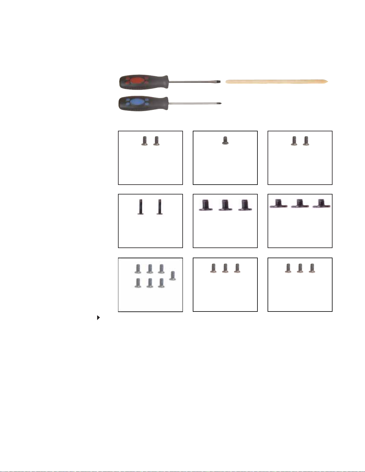
• Use a magn etized screwdriver for removing screws.
3
Replacing Convertible Notebook Compon ents
• When removing components that are attached to the convertible notebook by a cable,
unplug the cable before removing the screws, when possible, to avoid damagi ng the cable.
• As you remove components and screws, lay them toward the rear of your work surface
(behind the convertible notebook) or far enough to the side that your arms do not
accidentally brush them onto the floor.
• To help keep track of screws, try the following:
• Place each component’s screws in their own section of a parts sorter.
• Place each component’s screws next to the component on your work surface.
• Print the first page of each task, then place the page toward the rear of your work
surface. As you remove screws, place the screws in their respe ctive boxes on the pa ge.
• After loosening screws that are deeply recessed in a hole (for example, on the bottom
of the base assembly), you can leave the screws in the holes if you place small pieces
of masking tape over the hole openings. When reassembling the component, just
remove the tape and tighten the screws.
• When you place flat-headed screws on your work surface, stand them on their heads
to preve nt the screws fro m ro ll ing off th e t ab le.
Pre v enting static electric ity dischar ge
Warning
To avoid exposure to dangerous electrical voltages and moving parts, turn off your
convertible notebook, remove the battery, and unplug the power cord, modem cable, and
network cable before opening the case.
Tape
Warning
To prevent risk of electric shock, do not insert any object into the vent holes of the
convertible notebook.
Important
Before performing maintenance on the convertible notebook, you should read and
understand the information in this section.
The components inside your convertible notebook are extr emely sensitive to static electricity, also
known as electrostatic disch arge (ESD ).
Before performing maintenance on the convertible notebook, follow these guidel ines:
• Avoid static-causing surfaces such as carpeted floors, plastic, and packing foam.
• Remove components from their antistatic bags only when you are ready to use them. Do
not lay components on the outside of antistatic bags because only the inside of the bags
provide electrostatic protection.
• Always hold compone nts by their edges. Avoid touching the edge connectors. Never slide
components over any surface.
• Wear a grounding wrist strap (available at most electronics stores) and attach it to a bare
metal part of your workbench or other grounded connection.
• Touch a bare metal surface on your workbench or other grounded object.
Some of the procedures in this guide involve removing tape that holds cables or components. T wo
types of tape are used in this Gateway convertible notebook:
• Mylar, non-conductive tape is typically transparent, with a red or brown tint.
• Conductive tape is typically grey or silver.
If the existing tape cannot be reused, replace it with the same type (conductivity) of tape. Both
types of replacement tape should be non-ESD generating tape.
Do not use cellophane tape.
4
www.gateway.com
Preparing t he conv ertible not ebook
To prepare the convertible notebook for maintenance:
1 Make sure that the disc drive is empty.
2 Turn off the convertible notebook.
3 Make sure the LCD panel is in notebook mode, then close the LCD panel .
4 Disconnect your convertible notebook from the optional port replicator.
5 Disconnect the AC adapter, modem cable, and network cable, if connect ed to the convertible
notebook.
6 Disconnect all peripheral devices connected to the convertible notebook and remove an y PC
Cards.
7 Remove the batter y. For more in formatio n, see “Removing the battery” on page5.
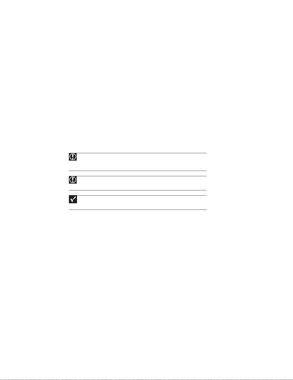
Removing the battery
To remove the battery:
1 Turn your co nver ti ble no teb oo k over so the bo ttom is facin g u p.
2 Slide the battery lock to the unlocked position , then slide the battery release latch.
3 Sli de the ba tter y o ut of t he bay.
5

Replacing Convertible Notebook Compon ents
Adding or replac ing memory modules
Important
Use only memory modules designed for this Gateway convertible notebook.
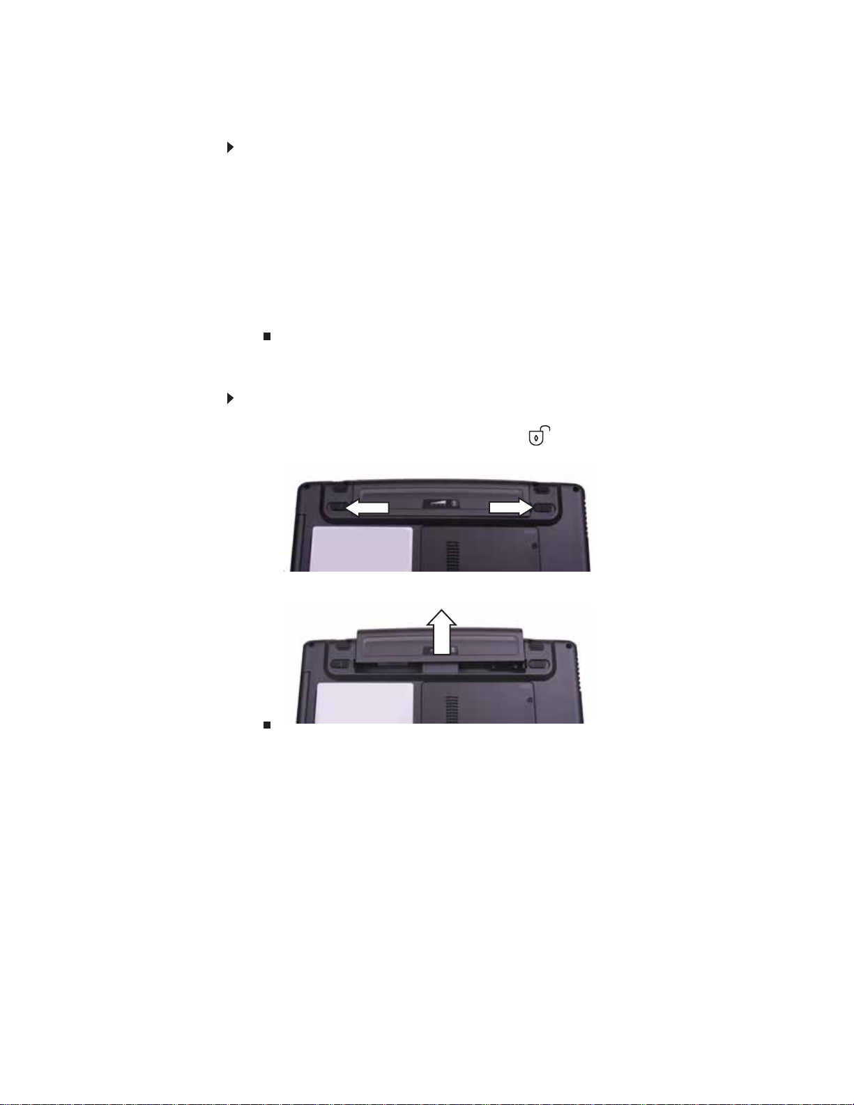
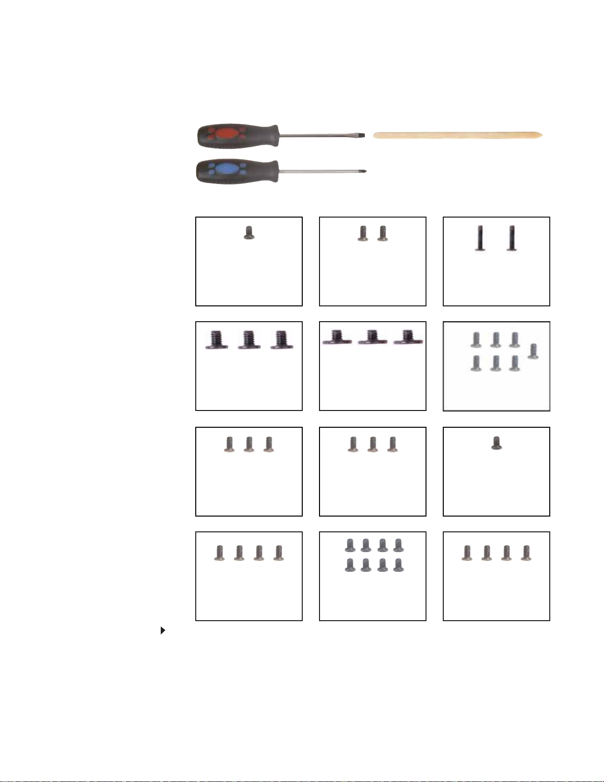
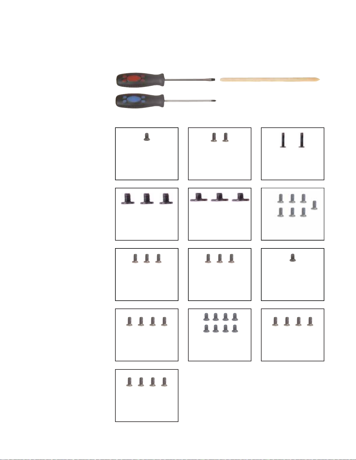
Tools you need to co mpl ete th is t ask:
Phillips #0 screwdriver
Memory
bay
To add or replace memory mo dules:
1 Complete the steps in “Preparing the convertible notebook” on page 5.
2 Loosen the two memory bay cover screws that secure the memory cover. (These screws
cannot be removed.)
Screw
Screw
3 Remove the memor y bay cover. Be careful not to break off the tabs located on the bottom
of the cover. If the cover does not remove easily, wiggle the cover to loosen it.
6

www.gateway.com
4 If you are removing a module, gently press outward on the clip at each end of the memory
module until the module tilts upward.
Clip
Clip
5 Pull the memory module out of the slot.
6 Hold the new or replacement module at a 30-deg ree angle and press it into the empty
memory slot. This module is keyed so it can only be inserted in one direction. If the module
does not fit, make sure that the notch in the module lines up with the tab in the memory bay.
7 Replace the memory bay cover, then tighten the cover screws.
7
Replacing Convertible Notebook Compon ents
Re placing the CMO S batt ery
Important
Use only CMOS batteries designed for this Gateway convertible notebook.
v
Tools you need to co mpl ete th is t ask:
Flat-blade driver Scribe or non-marring tool- OR -
Phillips #0 screwdriver
Memory
bay
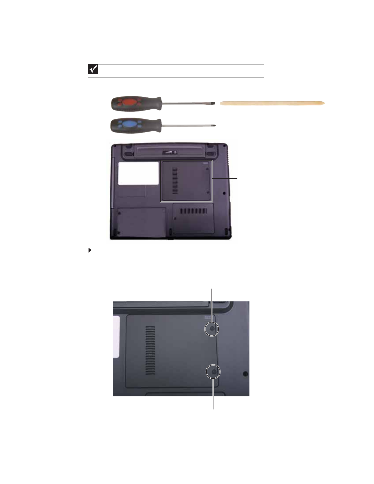
To replace the CMOS battery:
1 Complete the steps in “Preparing the convertible notebook” on page 5.
2 Loosen the two memory bay cover screws that secure the memory cover. (These screws
cannot be removed.)
Screw
8
Screw
3 Remove the memor y bay cover. Be careful not to break off the tabs located on the bottom
of the cover. If the cover does not remove easily, wiggle the cover to loosen it.
www.gateway.com
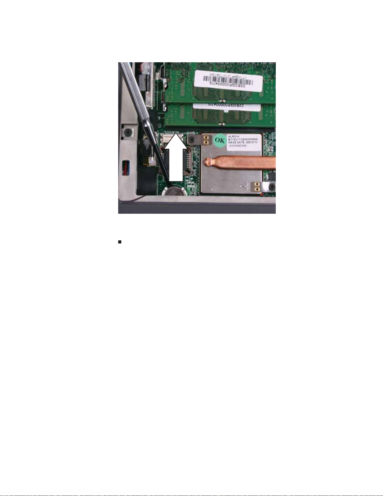
4 Insert the small flat -blade sc r e wd ri v er or non-marring tool under the old battery and gently
pry it up until it pops out of the socket.
5 Make s u re t he pos it ive (+ ) si de of th e n ew b atte r y i s fa cin g up, th en pr ess t he ba tter y in to
the socket until it snaps into pl ace.
6 Replace the memory bay cover, then tighten the cover screws.
9

Replacing Convertible Notebook Compon ents
Re placing the IEEE 8 02 . 11 w ireles s card
Tools you need to co mpl ete th is t ask:
Phillips #0 screwdriver
Screws removed during this task:
2 black 2.0*3.0 (IEE E
802.11 wireless card)
Wirele ss bay
To replace the IEEE 802.11 wireless card:
1 Complete the steps in “Preparing the convertible notebook” on page 5.
10
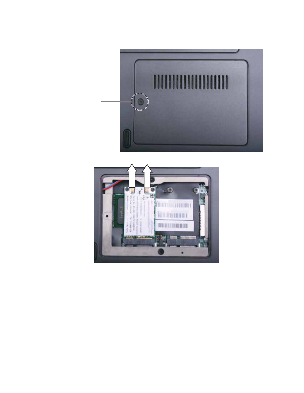
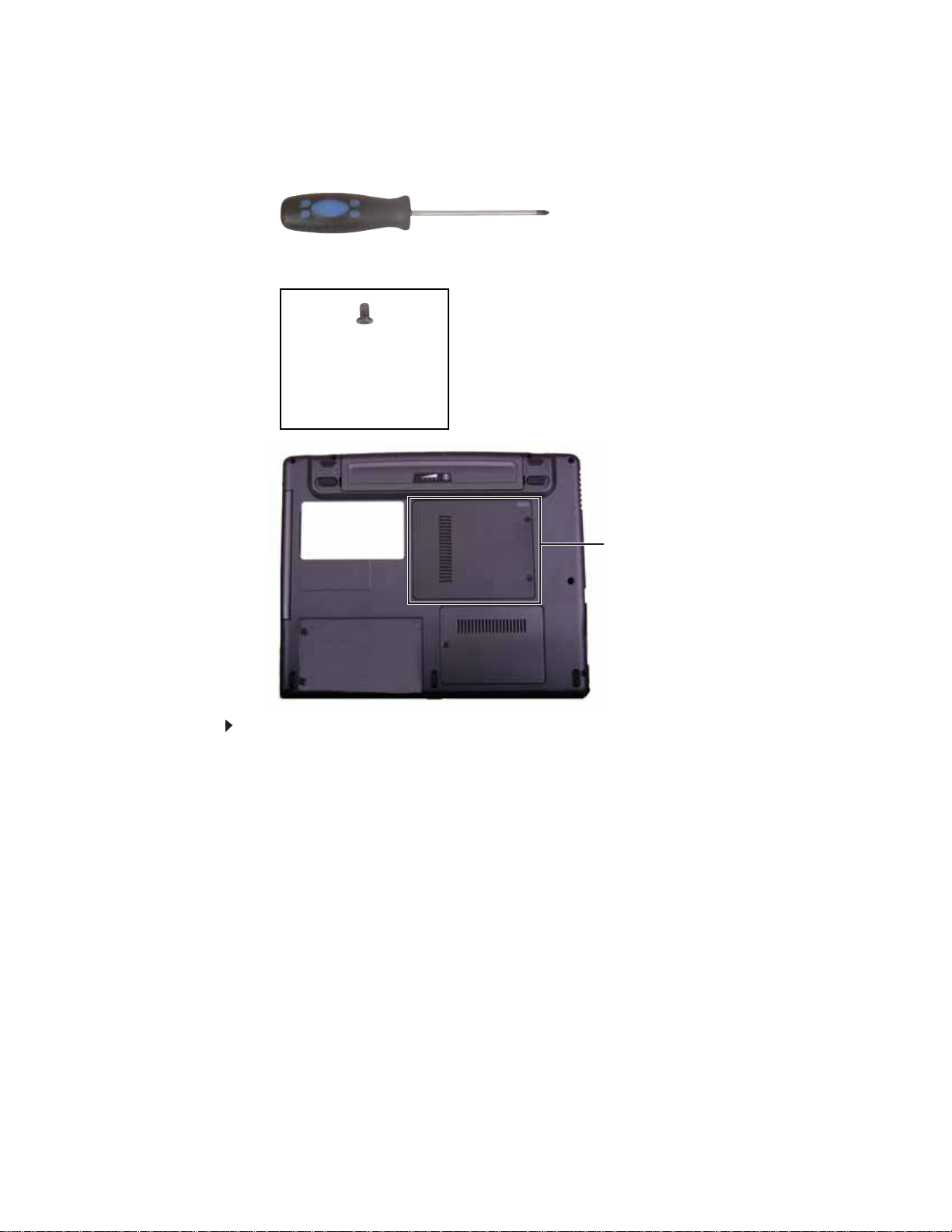
www.gateway.com
2 Loosen the wireless bay cover screw (this screw ca nnot b e removed) , the n remove the
wirel ess b ay c over.
Screw
3 Unplug the two antenna cables.
4 Move the antenna cables out of the way.
11
Replacing Convertible Notebook Compon ents
5 Remove the two screws holding the wireless module.
Screw
Screw
6 Pull the module out of the slot.
12
7 Insert the new module into the empty slot. This module is keyed so it can only be inserted
in one direction. If the module does not fit, make sure that the notch in the modul e lines
up with the tab in the mo dule s lot.
8 Move the antenna wires out of the way.
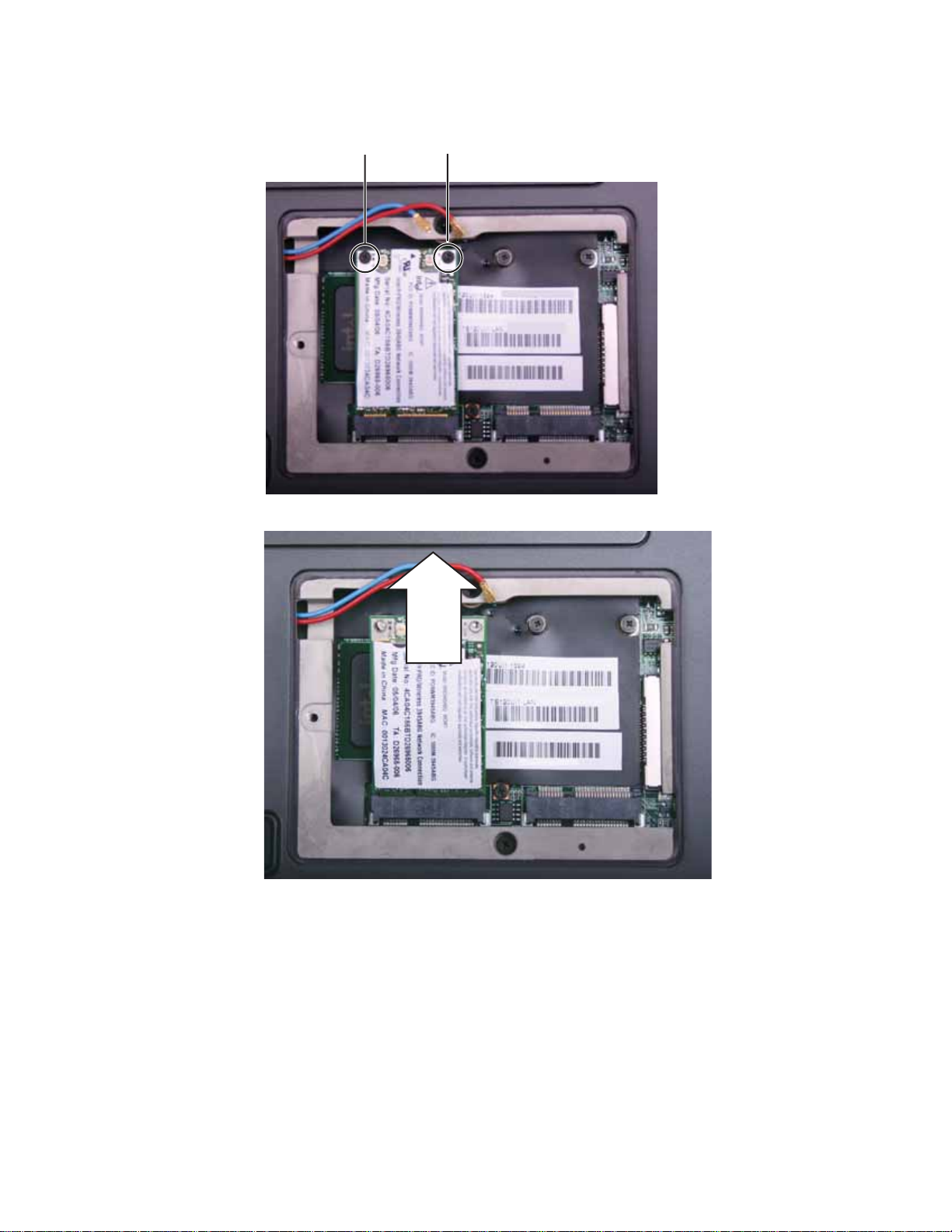
9 Press the module down, then replace the two screws remove in Step 5.

www.gateway.com
10 Reattach the blue antenna cable to the connector labelled MAIN or M, then reattach the
red antenna cable to the connector labelled AUX or A.
11 Replace the wireless bay c over, then tighten the cover screw.
13
Replacing Convertible Notebook Compon ents
Re placing the D VD dri ve
Tools you need to co mpl ete th is t ask:
Phillips #0 screwdriver
Screws removed during this task:
1 black 2.5*3.0 (DVD
drive)
Memory
bay
To replace the DVD drive:
1 Complete the steps in “Preparing the convertible notebook” on page 5.
14

www.gateway.com
2 Loosen the two memory bay cover screws that secure the memory cover. (These screws
cannot be removed.)
Screw
Screw
3 Remove the memor y bay cover. Be careful not to break off the tabs located on the bottom
of the cover. If the cover does not remove easily, wiggle the cover to loosen it.
4 Remove the screw that secures the DVD drive to your convertible notebook.
Screw
5 Carefully slide the drive out of the drive bay.
15

Replacing Convertible Notebook Compon ents
6 Slide the new DVD drive into the drive bay. Make sure that the drive fits securely in the bay.
7 Secure the DVD drive with the screw removed in Step4.
8 Replace the memory bay cover, then tighten the cover screws.
16

www.gateway.com
Re placing the har d driv e
Tools you need to co mpl ete th is t ask:
Phillips #0 screwdriver
Screws removed during this task:
2 black 2.5*3.0 (hard
drive)
Hard drive bay
To replace the hard drive:
4 black 3.0*3. 0 (hard
drive bracket)
1 Complete the steps in “Preparing the convertible notebook” on page 5.
2 Loosen the two hard dri v e ba y cov er scr ew s (thes e sc re ws cannot be remov ed), then remove
the hard drive bay cover.
Screw
Screw
17

Replacing Convertible Notebook Compon ents
3 Remove the two hard drive screws.
Screw
Screw
4 Pull on the plastic strip to slide the old h ard drive out of the convertible notebook.
18
5 Remove the four screws that secure the hard drive to the hard drive bracket.
Screw
Screw
Screw
Screw

www.gateway.com
6 Remove th e b rac ket fro m th e o ld dr ive.
7 Insert the new drive into the bracket, label side up, so the screw holes line up.
8 Replace the four screws that were rem oved in Step 5.
9 Slide the new hard drive into your convertible notebook, then replace the screws that were
remove d i n Step3.
10 Replace the hard drive bay cover, then tighten the cover screws.
19

Replacing Convertible Notebook Compon ents
Re placing the k e yboard
v
Tools you need to co mpl ete th is t ask:
Flat-blade driver Scribe or non-marring tool- OR -
To replace the keyboard:
1 Complete the steps in “Preparing the convertible notebook” on page 5.
2 Carefully open the LCD panel to the fully opened position.
3 Locate the three sprin g-clips se curing th e top of the keyboard. They are lo cated a bove the
SC, F9, and DEL keys.
E
Clip
Clip
Clip
20
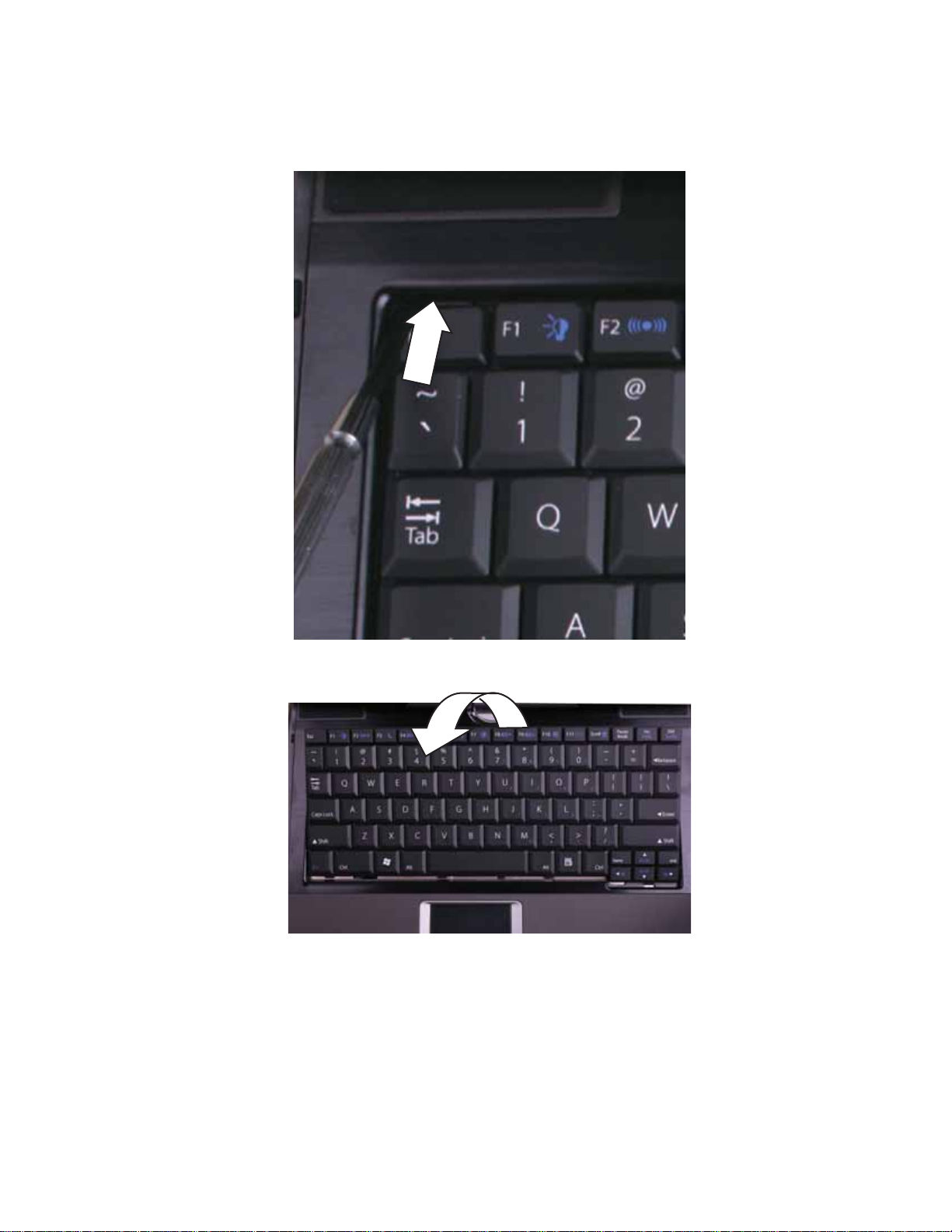
www.gateway.com
4 Insert the small flat-blade screwdriver or non-marring tool and gently slide each clip back.
As you do so, lift up on the keyboard so the clip will slide behind the keyboard when you
release the clip.
5 Lift the back edge of the keyboard and rotate the keyboard toward you so it lies keys-down
on top of your convertible notebook.
21

Replacing Convertible Notebook Compon ents
6 Slide the brown connector clips to the back of your convertible notebook, then remove the
cable. Be careful not to touch or damage any other components.
Clip
Clip
7 Lift th e o ld keyboa rd away from you r co nver ti ble no tebo ok .
8 Place the new keyboard keys-down on your convertible notebook with the space bar away
from you .
9 Make sure the brown keyboard connector clips are slid to the back of your convertible
notebook, insert the cable into the connector, then slide the brown connector clips forward
to lock the connector in place.
Important
The keyboard cable is correctly oriented if it is not twisted.
10 Rotate the keyboard toward the LCD panel until the keyboard is almostface-up.
11 Insert the tabs on the front edge of the keyboard into the slots under the palm rest. You
may need to pres s down on the keyboard keys along the front edge of the keyboard to seat
the retaining tabs into their corresponding slots.
12 Gently press the keyboard down until it is flat all the way across and the spring-clips are
securing the top of the keyboard. Be care ful n ot to dam age the LCD panel .
22
www.gateway.com
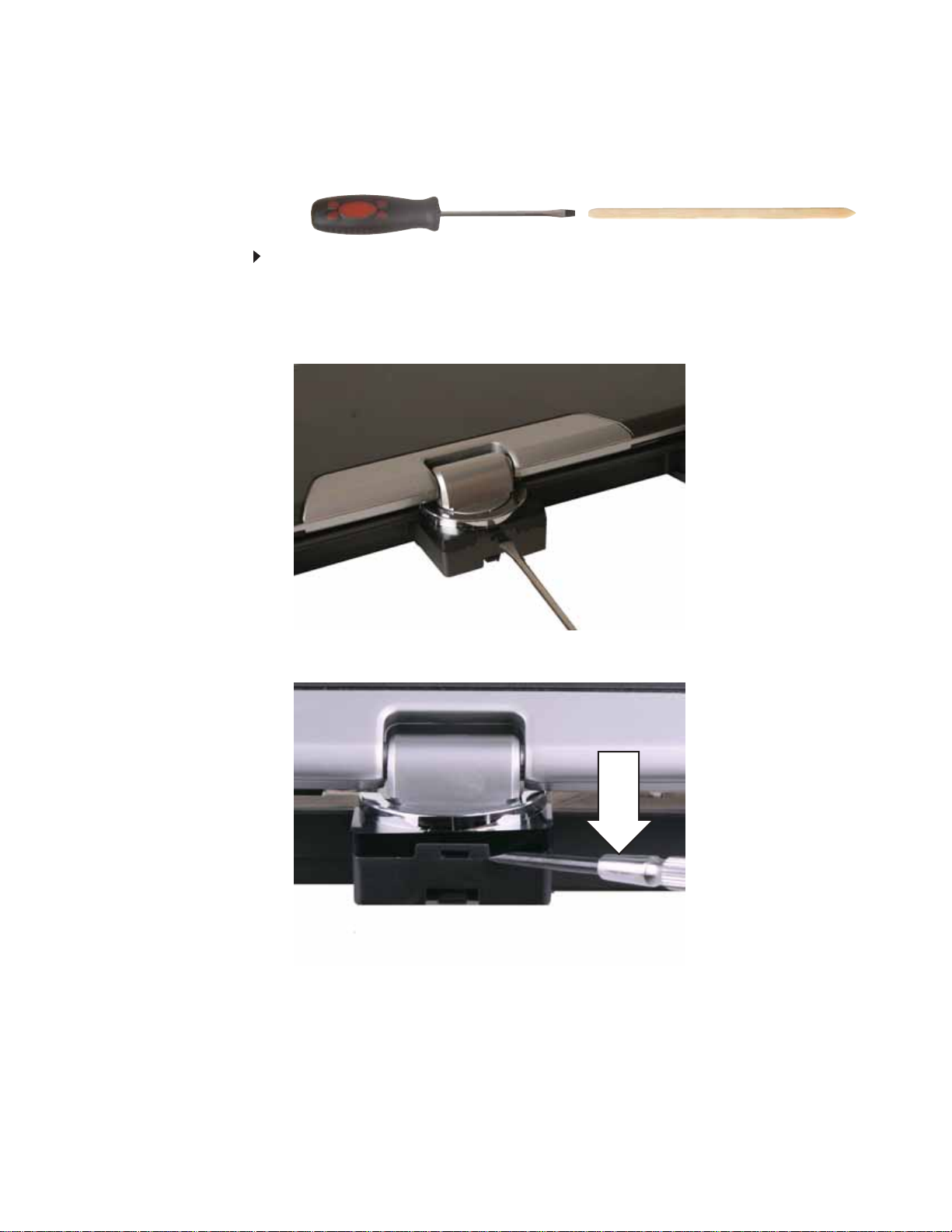
Re placing the hinge co ver
v
Tools you need to co mpl ete th is t ask:
Flat-blade driver Scribe or non-marring tool- OR -
To replace the hinge cover:
1 Complete the steps in “Preparing the convertible notebook” on page 5.
2 Close the LCD panel.
3 Insert a flat-blade screwdriver or non-marring tool into the slot on the hinge and press the
tab. The hinge cover should pop up.
4 Use the flat-blade screwdri v er or non-marr ing t ool to pry the hinge cover off the con vertible
notebook.
23

Replacing Convertible Notebook Compon ents
5 Slide the old hinge cover to the back and off of the convertible notebook.
6 Slide the new hinge cover over the hinge and snap it into place.
24

www.gateway.com
Re placing the palm r est
v
Tools you need to co mpl ete th is t ask:
Flat-blade driver Scribe or non-marring tool- OR -
Phillips #0 screwdriver
Screws removed during this task:
1 black 2.5*3.0 (DVD
drive)
3 black 2.5*3.0 (Palm
rest-DVD drive bay)
2 black 2.5*3.0 (hard
drive)
3 black 2.5*2.2 (Palm
rest-hard drive bay)
2 black 2.0*6.0 (Palm
rest-bottom)
7 black 2.5*4.5 (Palm
rest-bottom)
3 black 2.5*6.0 (Palm
rest-top)
To replace the palm rest:
1 Complete the steps in “Preparing the convertible notebook” on page 5.
2 Remove the mem ory bay cover by following the steps in “Adding or replacing memory
modules” on page 6.
3 Remove the wireless bay cover by following the steps in “Replacing the IEEE 802.11 wireless
card” on page10.
4 Remove the DVD drive by following the steps in “Replacing the DVD drive” on page 14.
5 Remove the hard drive by following the steps in “Replacing the hard drive” on page 17.
25

Replacing Convertible Notebook Compon ents
6 Remove the 15 screws shown in the following picture. Note the location of the screw types
and sizes.
Long screw
Screw
Short screw
Short screw
Screw
Screw
Screw
Short screw
Long screw
Large head
screw
Large
head
screw
Large head
screw
Screw
Screw
Screw
7 Turn the convertible notebook over so the top i s facing up.
8 Remove the keyboard by following the steps in “Replacing the keyboard” on page 20.
9 Slide the brown touchpad connector clips to the front, then remove the cable. Be careful not
to touch or damage any other components.
26
Clip
Clip

www.gateway.com
10 Remove the three screws shown in the following pi cture.
Screw
Screw
Screw
11 Disconnect the speaker cable.
12 Li ft t he pa lm r est asse mb ly c om ple tely fr om the co nvert ib le no tebo ok .
13 If the new palm rest does not include the touchpad cable, transfer the cable t o the new palm
rest. Go to Step 14.
-ORIf the new palm rest includes the touchpad cable, go to Step 17.
14 Turn the palm rest over so the back side is facing up .
27
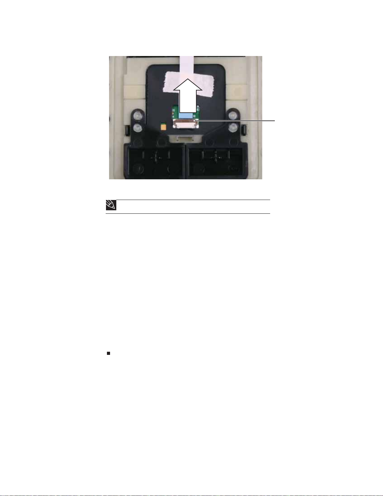
Replacing Convertible Notebook Compon ents
15 Flip the brown connector clip up, then remove the touchpad cable.
Clip
16 Make sure that the brown connector clip on the new palm rest is in the raised position, lay
the cable into the connector, then flip the con nector down onto the cable.
Tip
The cable is correctly oriented if the blue side is showing.
17 Place the new palm rest assembly onto the conve rtible notebook, then snap the assembly
into place.
18 Reconnect the speaker cable.
19 M ake sur e th e b rown tou chp ad con ne ctor cli ps are sli d to th e fro nt of t he co nvert ib le
notebook, insert the cable into the connector, then slide the brown connector clips back to
lock the cable in place.
20 Replace the three top palm rest screws removed in Step10.
21 Replace the keyboard by following the instructions in “Replacing the keyboard” on page20.
22 Turn th e c onve rti bl e n ote boo k ove r s o th e b otto m i s fa cing up .
23 Replace the 15 bottom pal m rest screws removed in Step 6.
24 Replace the hard drive by following the steps in “Replacing the hard drive” on page 17.
25 Replace the DVD drive by following the steps in “Replacing the DVD drive” on page 14.
26 Replace the wireless bay cover by following the steps in “Replacing the IEEE 802.11 wireless
card” on page10.
27 Replace the memory bay cover by following the steps in “Adding or replacing memory
modules” on page 6.
28
www.gateway.com
Re placing the Blue tooth module
v
Tools you need to co mpl ete th is t ask:
Flat-blade driver Scribe or non-marring tool- OR -
Phillips #0 screwdriver
Screws removed during this task:
1 black 2.5*3.0 (DVD
drive)
3 black 2.5*3.0 (Palm
rest-DVD drive bay)
2 black 2.5*3.0 (hard
drive)
3 black 2.5*2.2 (Palm
rest-hard drive bay)
2 black 2.0*6.0 (Palm
rest-bottom)
7 black 2.5*4.5 (Palm
rest-bottom)
3 black 2.5*6.0 (Palm
rest-top)
To replace the Bluetooth module:
1 Complete the steps in “Preparing the convertible notebook” on page 5.
2 Remove the mem ory bay cover by following the steps in “Adding or replacing memory
modules” on page 6.
3 Remove the wireless bay cover by following the steps in “Replacing the IEEE 802.11 wireless
card” on page10.
4 Remove the DVD drive by following the steps in “Replacing the DVD drive” on page 14.
5 Remove the hard drive by following the steps in “Replacing the hard drive” on page 17.
6 Remove the palm rest by following the steps in “Replacing the palm rest” on page 25.
29
Replacing Convertible Notebook Compon ents
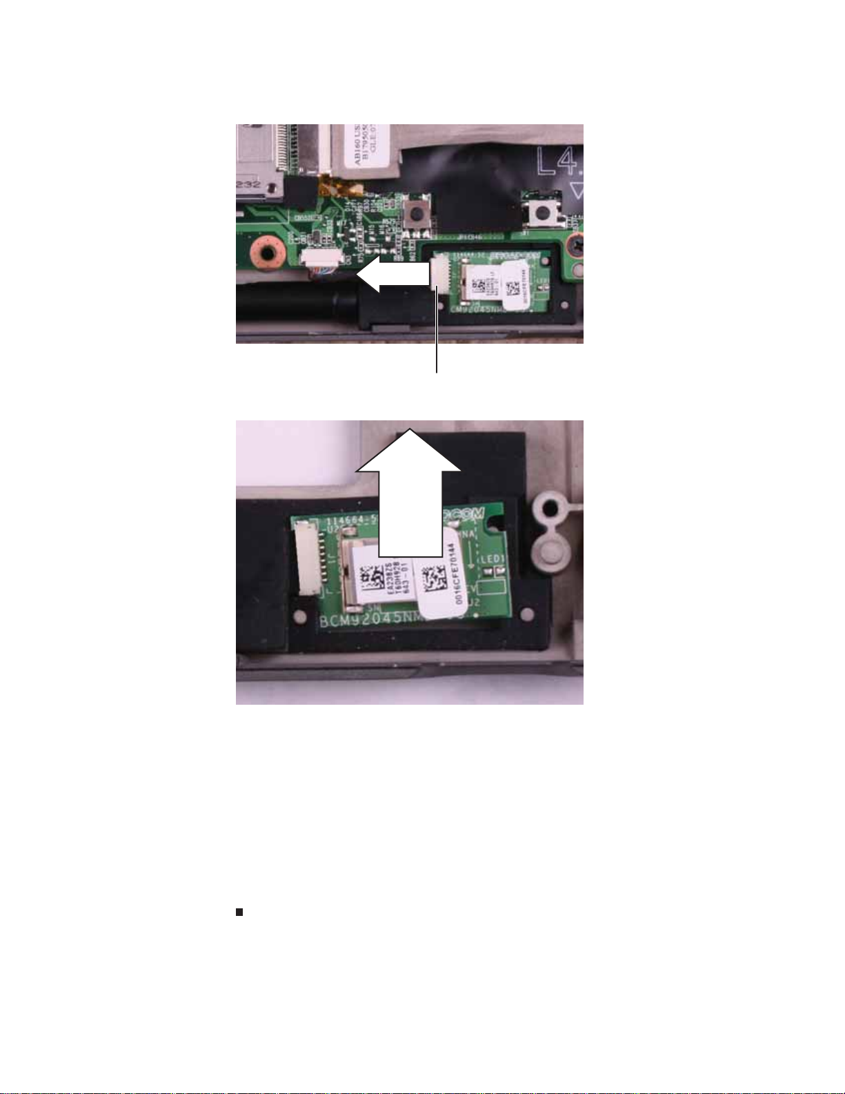
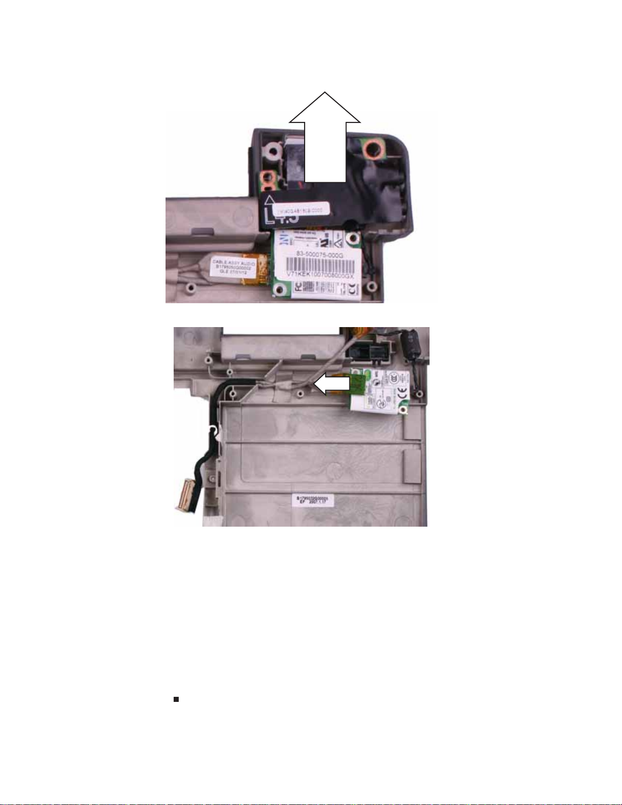
7 Disconnect the Bluetooth cable from the Bluetooth module.
Connector
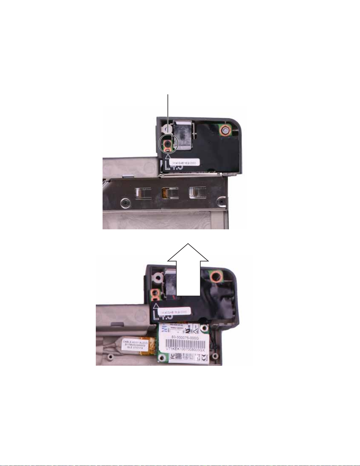
8 Lift the right end of the old Bluetooth module , then slide the module out of the rubber holder.
30
9 Insert the left end of the new Bluetooth module under the flap in the rubber holder, then
press the right end down. The notch in the right end of the modul e should fit around the
pin located in the holder.
10 Connect the Bluetooth cable to the Bluetooth module.
11 Replace the palm rest by following the steps in “Replacing the palm rest” on page25.
12 Replace the hard drive by following the steps in “Replacing the hard drive” on page 17.
13 Replace the DVD drive by following the steps i n “Replacing the DVD drive” on page 14.
14 Replace the wireless bay cover by following the steps i n “Replacing the IEEE 802.11 wireless
card” on page10.
15 Replace the memory b ay cover by following the steps in “Adding or replacing memory
modules” on page 6.

www.gateway.com
Re placing the U SB/Fire wire boar d
v
Tools you need to co mpl ete th is t ask:
Flat-blade driver Scribe or non-marring tool- OR -
Phillips #0 screwdriver
Screws removed during this task:
1 black 2.5*3.0 (DVD
drive)
3 black 2.5*3.0 (Palm
rest-DVD drive bay)
2 black 2.5*3.0 (hard
drive)
3 black 2.5*2.2 (Palm
rest-hard drive bay)
2 black 2.0*6.0 (Palm
rest-bottom)
7 black 2.5*4.5 (Palm
rest-bottom)
3 black 2.5*6.0 (Palm
rest-top)
To replace the USB/Firewire board :
1 black 2.5*4.5
(Reinforcement bracket)
1 Complete the steps in “Preparing the convertible notebook” on page 5.
2 Remove the mem ory bay cover by following the steps in “Adding or replacing memory
modules” on page 6.
3 Remove the wireless bay cover by following the steps in “Replacing the IEEE 802.11 wireless
card” on page10.
4 Remove the DVD drive by following the steps in “Replacing the DVD drive” on page 14.
5 Remove the hard drive by following the steps in “Replacing the hard drive” on page 17.
6 Remove the palm rest by following the steps in “Replacing the palm rest” on page 25.
31
Replacing Convertible Notebook Compon ents
7 Remove the screw holding the reinforcement bracket, then lift the bracket off of the
convertible notebook.
Screw
32
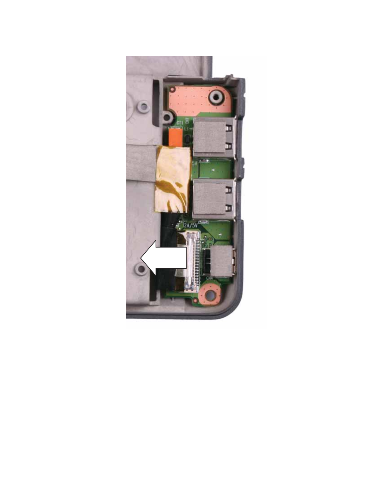
www.gateway.com
8 Disconnect the USB/Firewire cable from the USB/Firewire board.
33
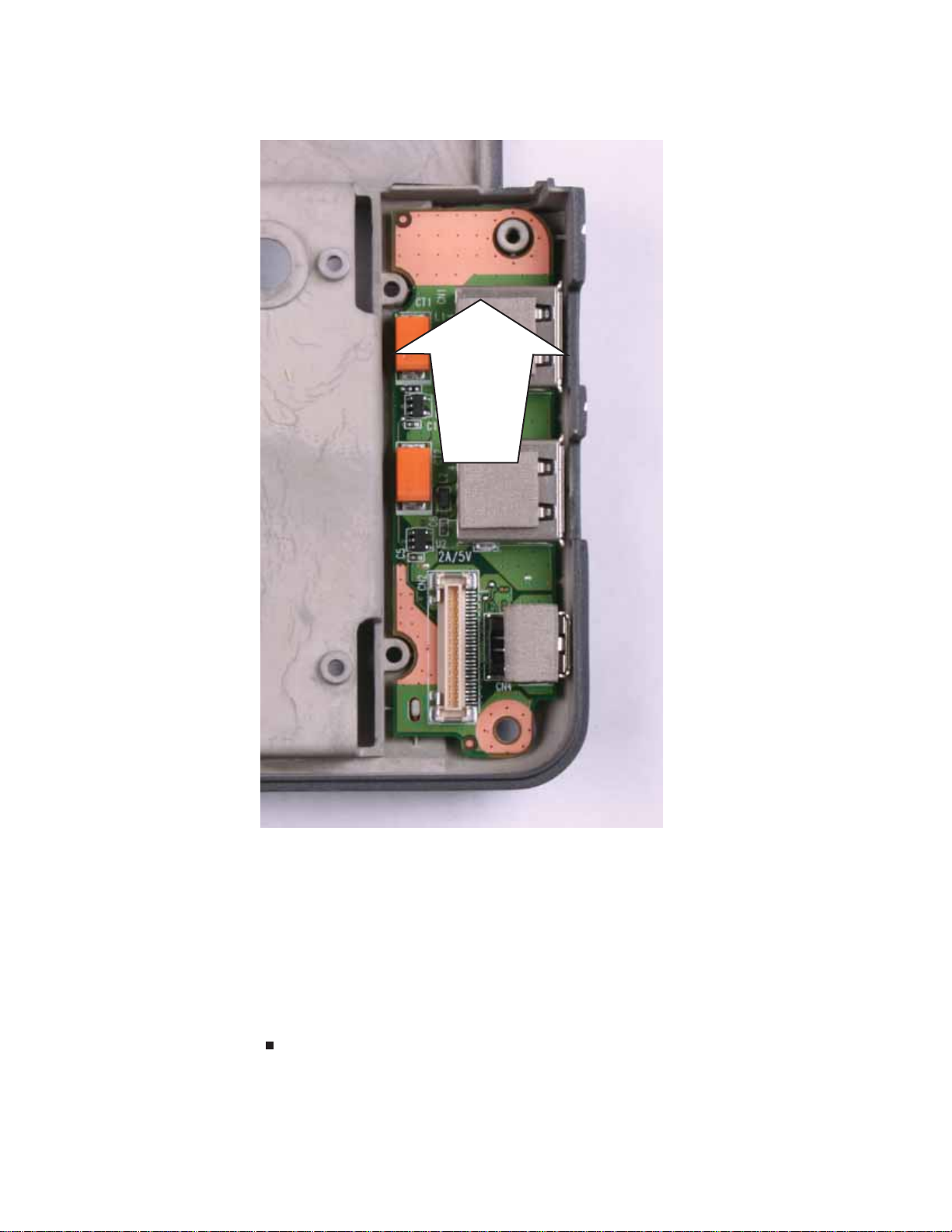
Replacing Convertible Notebook Compon ents
9 Remove the old USB/Firewire board from the convertible notebook.
34
10 Place the new USB/Firewire board into the convertible notebook. The holes in the board
should fit around the posts in the bay.
11 Connect the USB/Firewire cable to the USB/Firewire board.
12 Replac e the palm rest by following the steps in “Replacing the palm rest” on page25.
13 Replace the hard drive by following the steps in “Replacing the hard drive” on page 17.
14 Replace the DVD drive by following the steps in “Replacing the DVD drive” on page14.
15 Replace the wireless bay cover by following the steps in “Replacing the IEEE 802.11 wireless
card” on page10.
16 Replace the mem ory bay cover by following the steps in “Adding or replacing memor y
modules” on page 6.
www.gateway.com
Re placing the s yst em board
v
Tools you need to co mpl ete th is t ask:
Flat-blade driver Scribe or non-marring tool- OR -
Phillips #0 screwdriver
Screws removed during this task:
2 black 2.0*3.0 (IEE E
802.11 wireless card)
2 black 2.0*6.0 (Palm
rest-bottom)
1 black 2.5*3.0 (DVD
drive)
3 black 2.5*3.0 (Palm
rest-DVD drive bay)
2 black 2.5*3.0 (hard
drive)
3 black 2.5*2.2 (Palm
rest-h ard drive bay )
7 black 2.5*4.5 (Palm
rest-bottom)
To replace the system board:
3 black 2.5*6.0 (Palm
rest-top)
3 black 2.5*4.5 (System
board)
1 Complete the steps in “Preparing the convertible notebook” on page 5.
2 Remove the memor y by following the steps in “Adding or replacing memory modules” on
page 6.
35
Replacing Convertible Notebook Compon ents
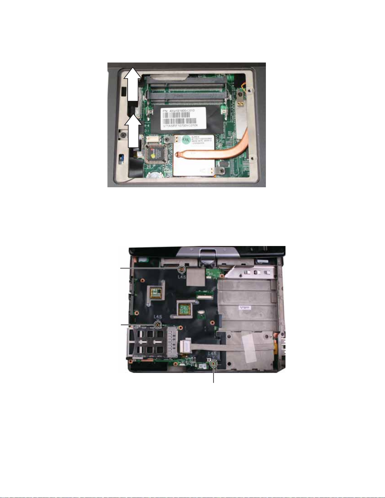
3 Carefully unplug the LCD video cable and the mod em/audio cable from the system board.
Make sure you pull the plastic tabs, not the cables.
4 Remove the wireless card by following the steps in “Replacing the IEEE 80 2.11 wireless card”
on page 10.
5 Remove the DVD drive by following the steps in “Replacing the DVD drive” on page 14.
6 Remove the hard drive by following the steps in “Replacing the hard drive” on page 17.
7 Remove the palm rest by following the steps in “Replacing the palm rest” on page 25.
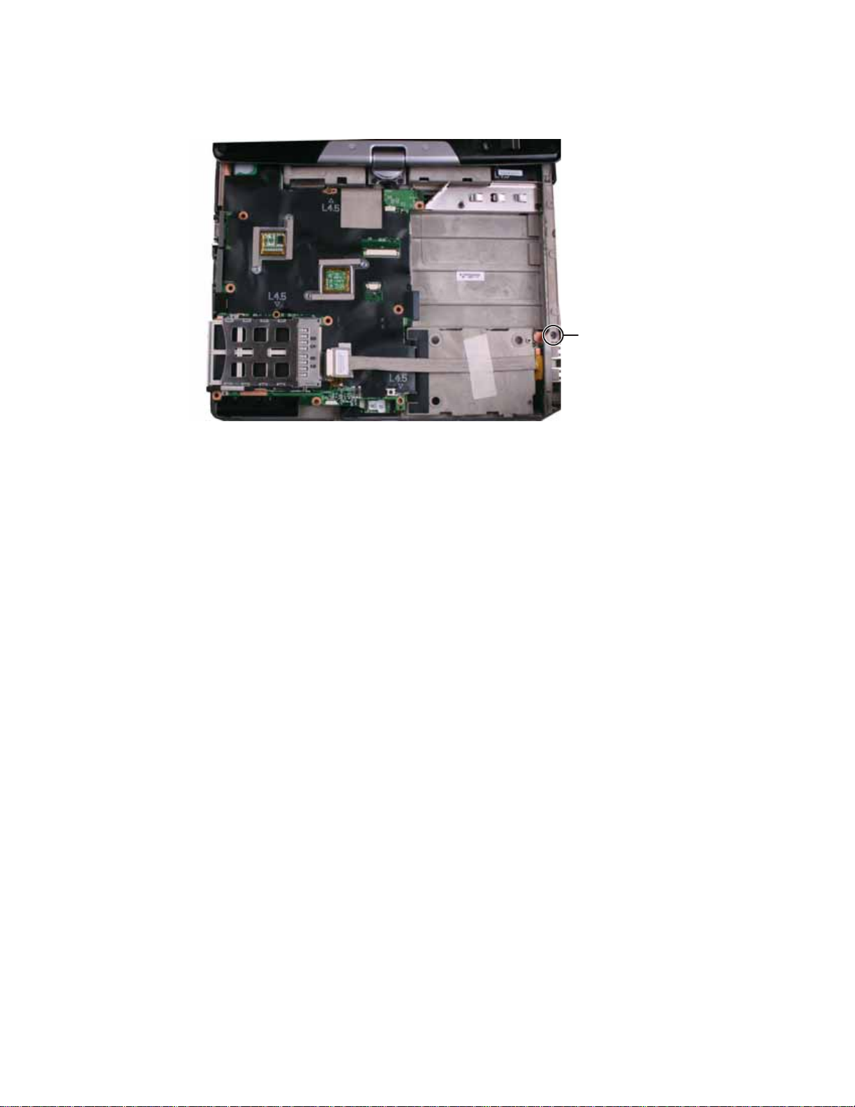
8 Remove the three screws shown in the following picture.
Screw
Screw
Screw
36
www.gateway.com
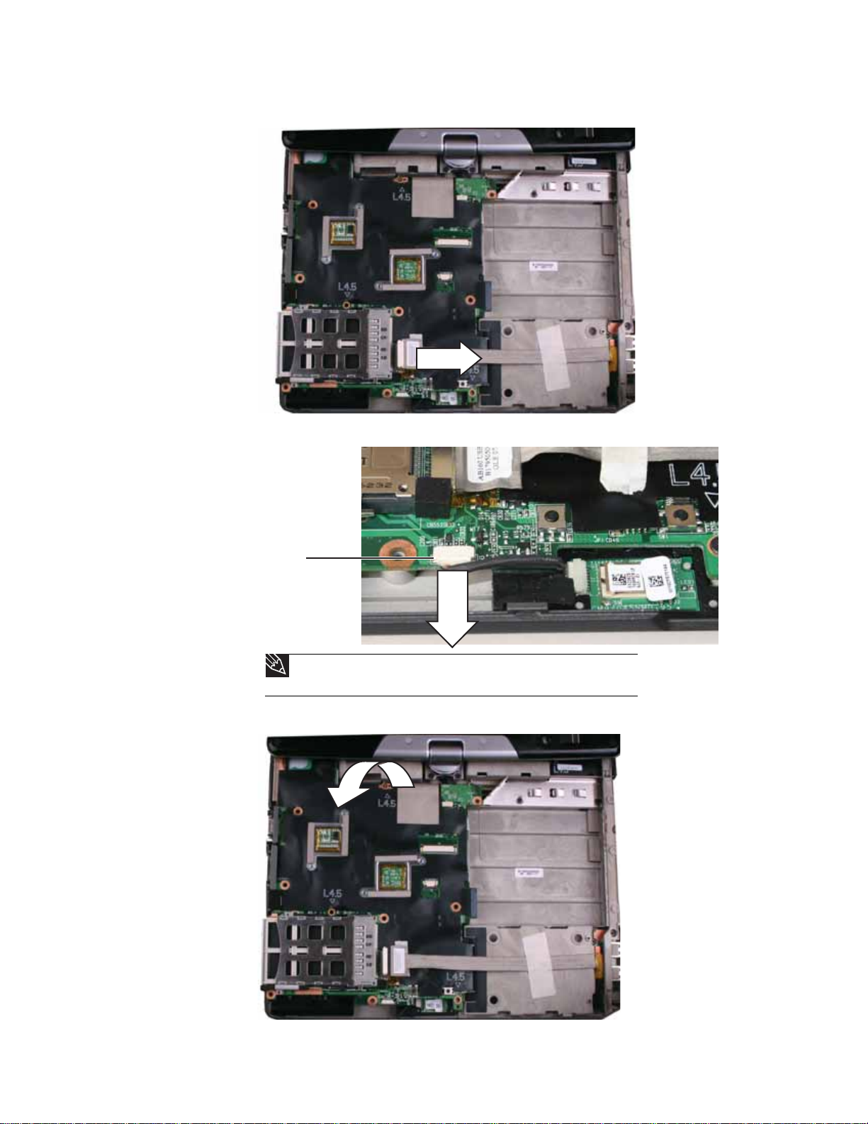
9 Disconnect the USB/Firewire cable from the system board.
10 Disconnect the Bluetooth cable from the system board.
Connector
Tip
Remove the digital pen before disconnecting the Bluetooth cable from the
system board.
11 Remove the old system board from the convertible notebook.
37

Replacing Convertible Notebook Compon ents
12 Place the new system board into the convertible notebook.
13 Connect the Bluetooth cable to the system board.
14 Connect the USB cable to the system board.
15 Replace the three screws removed in Step 8.
16 Replac e the palm rest by following the steps in “Replacing the palm rest” on page25.
17 Replace the hard drive by following the steps in “Replacing the hard drive” on page17.
18 Replace the DVD drive by following the steps in “Replacing the DVD drive” on page 14.
19 Reinstall the wirele s s card by follow ing th e st e p s in “Replacing the IEEE 802. 11 wireless card”
on page 10.
20 Plug the LCD video cable and the modem/audio cable into the system board.
21 Reinstall the memory by following the steps in “Adding or replacing memory modules” on
page 6.
38

www.gateway.com
Re placing the cooling f an
v
Tools you need to co mpl ete th is t ask:
Flat-blade driver Scribe or non-marring tool- OR -
Phillips #0 screwdriver
Screws removed during this task:
1 black 2.5*3.0 (DVD
drive)
3 black 2.5*3.0 (Palm
rest-DVD drive bay)
2 black 2.5*3.0 (hard
drive)
3 black 2.5*2.2 (Palm
rest-hard drive bay)
2 black 2.0*6.0 (Palm
rest-bottom)
7 black 2.5*4.5 (Palm
rest-bottom)
3 black 2.5*6.0 (Palm
rest-top)
To replace the cooling fan:
3 black 2.5*4.5 (System
board)
2 black 2.0*3.0 (cooling
fan)
1 Complete the steps in “Preparing the convertible notebook” on page 5.
2 Remove the mem ory bay cover by following the steps in “Adding or replacing memory
modules” on page 6.
3 Disconnect the wireless antenna wires by following the steps in “Replacing the IEEE 802.11
wireless card” on pag e 10.
4 Remove the DVD drive by following the steps in “Replacing the DVD drive” on page 14.
5 Remove the hard drive by following the steps in “Replacing the hard drive” on page 17.
6 Remove the palm rest by following the steps in “Replacing the palm rest” on page 25.
7 Remove the s ystem board b y f ollowing the steps in “Replacing the sy stem boar d” on page 35.
8 Turn the syste m b oar d ove r so the bo ttom is facin g u p.
39

Replacing Convertible Notebook Compon ents
9 Disc on ne ct th e fan from th e sys tem boa rd.
10 Remove the two screws that secure the c oolin g fan to the system boa rd.
Screw
Screw
40

www.gateway.com
11 Remove the old fan from the system b oard.
12 Ins tall the new fan on the system board, then replace the screws removed in Step 10.
13 Connect the fan to the system board.
14 Replace the syst em board by following the steps in “Replac ing the s y st em board” on page35.
15 Replace the palm rest by following the steps in “Replacing the palm rest” on page 25.
16 Replace the hard drive by following the steps in “Replacing the hard drive” on page 17.
17 Replace the DVD drive by following the steps in “Replacing the DVD drive” on page14.
18 Re co nne ct th e a nte nna wir es to the wir ele ss c ard by fol lowi ng the ste ps i n “Replacing the
IEEE 802.11 wireless card” on page10.
19 Replace the mem ory bay cover by following the steps in “Adding or replacing memory
modules” on page 6.
41

Replacing Convertible Notebook Compon ents
Re placing the modem
v
Tools you need to co mpl ete th is t ask:
Flat-blade driver Scribe or non-marring tool- OR -
Phillips #0 screwdriver
Screws removed during this task:
1 black 2.5*3.0 (DVD
drive)
3 black 2.5*3.0 (Palm
rest-DVD drive bay)
2 black 2.5*3.0 (hard
drive)
3 black 2.5*2.2 (Palm
rest-hard drive bay)
2 black 2.0*6.0 (Palm
rest-bottom)
7 black 2.5*4.5 (Palm
rest-bottom)
42
3 black 2.5*6.0 (Palm
rest-top)
2 black 2.0*3.0 (mode m)
To replace the modem:
3 black 2.5*4.5 (System
board)
2 black 2.5*4.5 (modem/
audio cable shield)
1 Complete the steps in “Preparing the convertible notebook” on page 5.
2 Remove the mem ory bay cover by following the steps in “Adding or replacing memory
modules” on page 6.
3 Disc on nect the wire less ante nn a wire s by fol lowi ng th e s teps in “Replacing the IEEE 802.11
wireless card” on pag e 10.

www.gateway.com
4 Remove the DVD drive by following the steps in “Replacing the DVD drive” on page 14.
5 Remove the hard drive by following the steps in “Replacing the hard drive” on page 17.
6 Remove the palm rest by following the steps in “Replacing the palm rest” on page 25.
7 Remove the s ystem board b y f ollowing the steps in “Replacing the sy stem boar d” on page 35.
8 Remove the two screws that secure the modem/audio cable shield to the convertible
notebook.
Screw
Screw
9 Remove the mode m/audio cable shield.
10 Remove the two screws that secure the modem to the convertible notebook.
Screw
Screw
43
Replacing Convertible Notebook Compon ents
11 Lift the modem out of the convertible notebook.
12 Turn the modem over, then disconnect the modem cable from the old modem.
44
13 Connect the modem cable to the new modem.
14 Replace the modem so th at the cable s from both the modem and the audio board go under
the mode m, the n repla ce the screws removed in Step 10.
15 Replace the modem/audio cab le shield, then replace the screws remove d in Step 8.
16 Replace the s ystem board by f ollowing the steps in “Replacing t he sy st em boar d” on page35.
17 Replace the palm rest by following the steps in “Replacing the palm rest” on page 25.
18 Replace the hard drive by following the steps in “Replacing the hard drive” on page 17.
19 Replace the DVD drive by following the steps i n “Replacing the DVD drive” on page 14.
20 Reco nn ect the an ten na wi res to th e wi rel ess car d by follo win g th e s teps in “Replacing the
IEEE 802.11 wireless card” on page10.
21 Replace the mem ory bay cover by following the steps in “Adding or replacing memor y
modules” on page 6.

www.gateway.com
Re placing the a udio board
v
Tools you need to co mpl ete th is t ask:
Flat-blade driver Scribe or non-marring tool- OR -
Phillips #0 screwdriver
Screws removed during this task:
1 black 2.5*3.0 (DVD
drive)
3 black 2.5*3.0 (Palm
rest-DVD drive bay)
2 black 2.5*3.0 (hard
drive)
3 black 2.5*2.2 (Palm
rest-hard drive bay)
2 black 2.0*6.0 (Palm
rest-bottom)
7 black 2.5*4.5 (Palm
rest-bottom)
3 black 2.5*6.0 (Palm
rest-top)
2 black 2.0*3.0 (mode m)
To replace the audio board:
3 black 2.5*4.5 (System
board)
1 black 2.5*4.5 (audio
board)
2 black 2.5*4.5 (modem/
audio cable shield)
1 Complete the steps in “Preparing the convertible notebook” on page 5.
2 Remove the mem ory bay cover by following the steps in “Adding or replacing memory
modules” on page 6.
3 Disconnect the wireless antenna wires by following the steps in “Replacing the IEEE 802.11
wireless card” on pag e 10.
4 Remove the DVD drive by following the steps in “Replacing the DVD drive” on page 14.
45
Replacing Convertible Notebook Compon ents
5 Remove the hard drive by following the steps in “Replacing the hard drive” on page 17.
6 Remove the palm rest by following the steps in “Replacing the palm rest” on page 25.
7 Remove the s ystem board b y f ollowing the steps in “Replacing the sy stem boar d” on page 35.
8 Remove the mode m by following the steps in “Replacing the modem” on page 42.
9 Remove the screw that secures the aud io bo ard to the convertible notebo ok.
Screw
10 Lift bo th the aud io bo ard and th e mod em ou t of the convertibl e noteboo k.
46
www.gateway.com
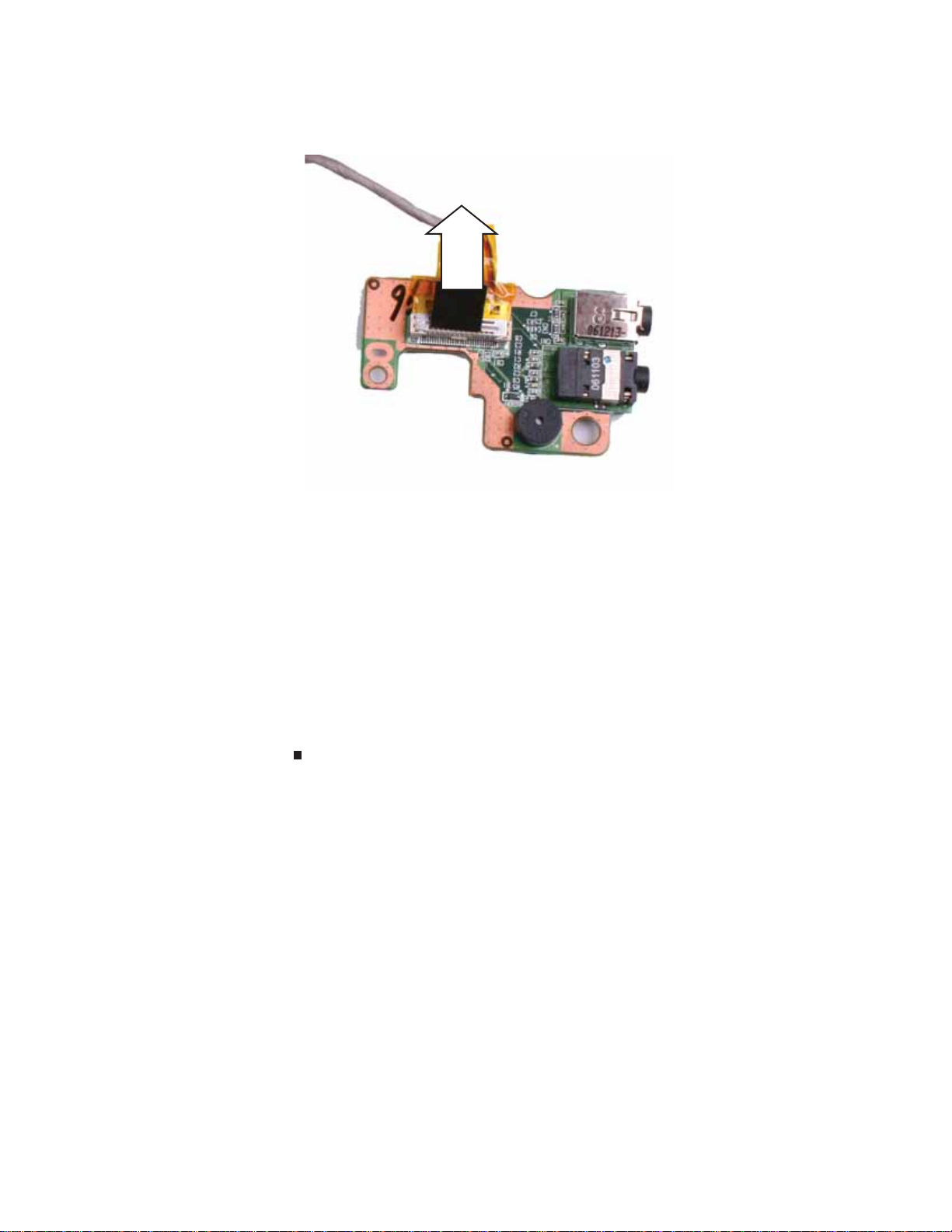
11 Turn the audio board over, then disconnect the audio cable from the old audio board. Make
sure you pull the plastic tab, not the cable.
12 Connect the audio cable to the new audio board.
13 Pla c e the new audio board so that th e l a rge p ost i n th e b ay fit s within th e l a rge ho l e i n the
board, then replace the screw removed in Step 9.
14 Replace the modem by following the steps in “Replacing the modem” on page 42.
15 Replace the system board by following the steps in “Replacing the s y stem boa rd” on page35.
16 Replace the palm rest by following the steps in “Replacing the palm rest” on pag e 25.
17 Replace the hard drive by following the steps in “Replacing the hard drive” on page17.
18 Replace the DVD drive by following the steps in “Replacing the DVD drive” on page 14.
19 Re co nn ect the ante nn a wi res to the wi rel ess car d by fo llo win g th e s teps in “Replacing the
IEEE 802.11 wireless card” on page10.
20 Replace the memory bay cover by following the steps in “Adding or replacing memory
modules” on page 6.
47
Replacing Convertible Notebook Compon ents
Re placing the modem jac k
v
Tools you need to co mpl ete th is t ask:
Flat-blade driver Scribe or non-marring tool- OR -
Phillips #0 screwdriver
Screws removed during this task:
1 black 2.5*3.0 (DVD
drive)
3 black 2.5*3.0 (Palm
rest-DVD drive bay)
2 black 2.5*3.0 (hard
drive)
3 black 2.5*2.2 (Palm
rest-hard drive bay)
2 black 2.0*6.0 (Palm
rest-bottom)
7 black 2.5*4.5 (Palm
rest-bottom)
48
3 black 2.5*6.0 (Palm
rest-top)
2 black 2.0*3.0 (mode m)
To replace the modem jack:
3 black 2.5*4.5 (System
board)
1 black 2.5*4.5 (audio
board)
2 black 2.5*4.5 (modem/
audio cable shield)
1 Complete the steps in “Preparing the convertible notebook” on page 5.
2 Remove the mem ory bay cover by following the steps in “Adding or replacing memory
modules” on page 6.
3 Disc on nect the wire less ante nn a wire s by fol lowi ng th e s teps in “Replacing the IEEE 802.11
wireless card” on pag e 10.
4 Remove the DVD drive by following the steps in “Replacing the DVD drive” on page 14.
www.gateway.com
5 Remove the hard drive by following the steps in “Replacing the hard drive” on page 17.
6 Remove the palm rest by following the steps in “Replacing the palm rest” on page 25.
7 Remove the s ystem board b y f ollowing the steps in “Replacing the sy stem boar d” on page 35.
8 Remove the mode m by following the steps in “Replacing the modem” on page 42.
9 Remove the audio b oard by following the steps in “Replacing the audio board” on page45.
10 D isc onn ect the mo dem ja ck fro m t he m od em.
11 Use th e pl as tic ta b to li ft th e o ld mo de m j ack out of the c onver ti ble no teb oo k.
12 S li de the new mo de m j ack in to th e c onve rti b le n ote bo ok .
13 Reconnect the modem jack to the modem.
14 Replace the audio board by following the steps in “Replacing the audio board” on page 45.
15 Replace the modem by following the steps in “Replacing the mode m” on page 42.
16 Replace the s ystem board by f ollowing the steps in “Replacing t he sy st em board” o n page35.
17 Replace the palm rest by following the steps in “Replacing the palm rest” on page 25.
18 Replace the hard drive by following the steps in “Replacing the hard drive” on page 17.
19 Replace the DVD drive by following the steps i n “Replacing the DVD drive” on page 14.
49

Replacing Convertible Notebook Compon ents
20 Reco nn ect the an ten na wi res to th e wi rel ess car d by follo win g th e s teps in “Replacing the
IEEE 802.11 wireless card” on page10.
21 Replace the mem ory bay cover by following the steps in “Adding or replacing memor y
modules” on page 6.
50
www.gateway.com
Re placing the L CD a ssembl y
v
Tools you need to co mpl ete th is t ask:
Flat-blade driver Scribe or non-marring tool- OR -
Phillips #0 screwdriver
Screws removed during this task:
1 black 2.5*3.0 (DVD
drive)
3 black 2.5*3.0 (Palm
rest-DVD drive bay)
2 black 2.5*3.0 (hard
drive)
3 black 2.5*2.2 (Palm
rest-hard drive bay)
2 black 2.0*6.0 (Palm
rest-bottom)
7 black 2.5*4.5 (Palm
rest-bottom)
3 black 2.5*6.0 (Palm
rest-top)
4 black 2.5*6.0 (LCD
panel hinge)
To replace the LCD assembly:
3 black 2.5*4.5 (System
board)
1 black 2.0*3.0 (LCD
grounding screw)
1 Complete the steps in “Preparing the convertible notebook” on page 5.
2 Remove the mem ory bay cover by following the steps in “Adding or replacing memory
modules” on page 6.
3 Disconnect the wireless antenna wires by following the steps in “Replacing the IEEE 802.11
wireless card” on pag e 10.
4 Remove the DVD drive by following the steps in “Replacing the DVD drive” on page 14.
51
Replacing Convertible Notebook Compon ents
5 Remove the hard drive by following the steps in “Replacing the hard drive” on page 17.
6 Remove the hinge cover by following the steps in “Replacing the hinge cover” on page 23.
7 Remove the palm rest by following the steps in “Replacing the palm rest” on page 25.
8 Remove the s ystem board b y f ollowing the steps in “Replacing the sy stem boar d” on page 35.
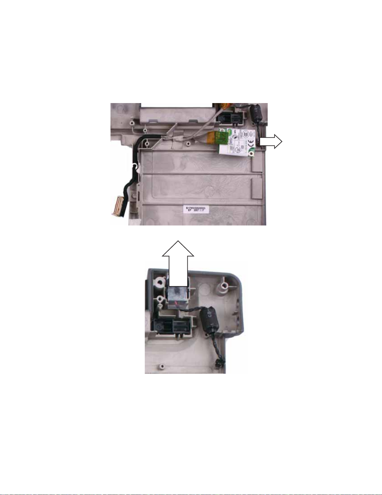
9 Remove any tape holding the antenna wires and LCD cable, then gently pull the antenna
wires out of the wireless bay.
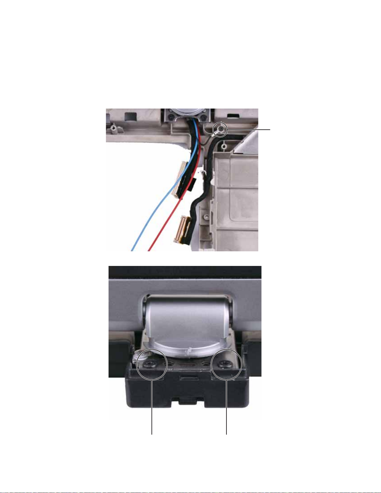
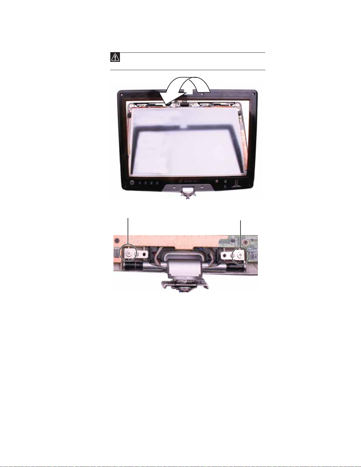
10 Remove the LCD grounding screw.
Screw
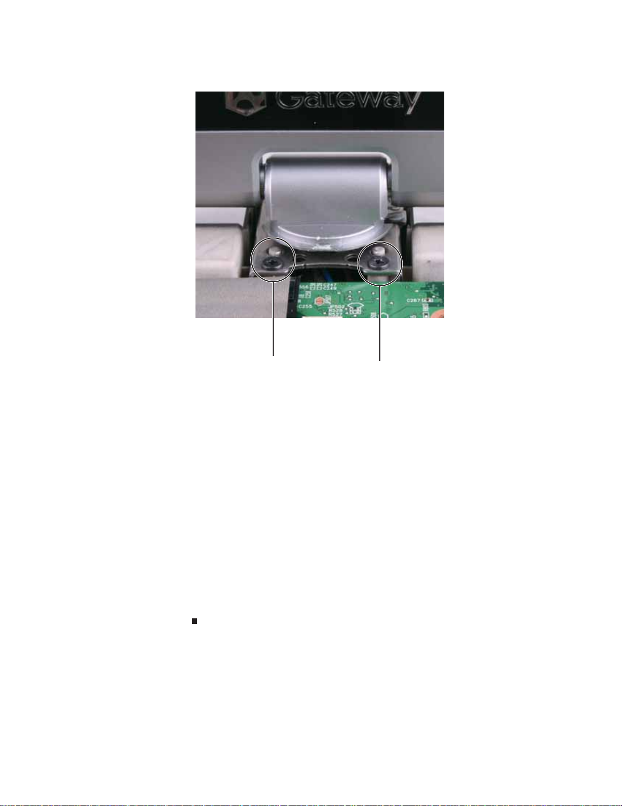
11 Close the LCD panel, then remove the two rear LCD hinge screws.
Screw
Screw
52
www.gateway.com
12 Ca refully open the LCD panel, then remove the two front LCD hinge screws.
Screw Screw
13 Lift the old LCD assembly off of the convertible notebook.
14 Place the new LCD assembly on the conv ertible notebook. Make sure that the antenna wires
and LCD cable are routed betwee n the front hinge screw posts.
15 Replace the screws removed in Step 12.
16 Ca refully close the LCD panel, then replace the screws removed in Step 11.
17 Open the LCD panel, then replace the grounding screw removed in Step10.
18 Fe ed the an ten na wi res into th e wi rel ess bay.
19 Replace any tape that held the antenna wires and LCD ca ble.
20 Replace the system board by following the steps in “Replaci ng the s y stem boar d” on page35.
21 Replace the palm rest by following the steps in “Replacing the palm rest” on pag e 25.
22 Replace the hinge cover by following the steps in “Replacing the hinge cover” on page 23.
23 Replace the hard drive by following the steps in “Replacing the hard drive” on page17.
24 Replace the DVD drive by following the steps in “Replacing the DVD drive” on page 14.
25 Reco nn ect the an ten na wi res to th e wi rel ess car d by follo win g th e s teps in “Replacing the
IEEE 802.11 wireless card” on page10.
26 Replace the memory bay cover by following the steps in “Adding or replacing memory
modules” on page 6.
53

Replacing Convertible Notebook Compon ents
Re placing the finger print reader
v
Tools you need to co mpl ete th is t ask:
Flat-blade driver Scribe or non-marring tool- OR -
Phillips #0 screwdriver
Screws removed during this task:
1 black 2.5*3.0 (DVD
drive)
3 black 2.5*3.0 (Palm
rest-DVD drive bay)
2 black 2.5*3.0 (hard
drive)
3 black 2.5*2.2 (Palm
rest-hard drive bay)
2 black 2.0*6.0 (Palm
rest-bottom)
7 black 2.5*4.5 (Palm
rest-bottom)
54
3 black 2.5*6.0 (Palm
rest-top)
4 black 2.5*6.0 (LCD
panel hinge)
To replace the fingerprint reader:
3 black 2.5*4.5 (System
board)
8 black 2.0*3.0 (LCD
assembly)
1 black 2.0*3.0 (LCD
grounding screw)
2 black 2.0*2.5
(fingerpri nt read er)
1 Complete the steps in “Preparing the convertible notebook” on page 5.
2 Remove the mem ory bay cover by following the steps in “Adding or replacing memory
modules” on page 6.
3 Disc on nect the wire less ante nn a wire s by fol lowi ng th e s teps in “Replacing the IEEE 802.11
wireless card” on pag e 10.
4 Remove the DVD drive by following the steps in “Replacing the DVD drive” on page 14.

www.gateway.com
5 Remove the hard drive by following the steps in “Replacing the hard drive” on page 17.
6 Remove the hinge cover by following the steps in “Repl acing the hinge cover” on page 23.
7 Remove the palm rest by following the steps in “Replacing the palm rest” on page 25.
8 Remove the s ystem board b y f ollowing the steps in “Replacing the sy stem boar d” on page 35.
9 Remove t he L CD as sembly b y f ollow ing the st eps in “R eplacing the LC D assembly” on page51.
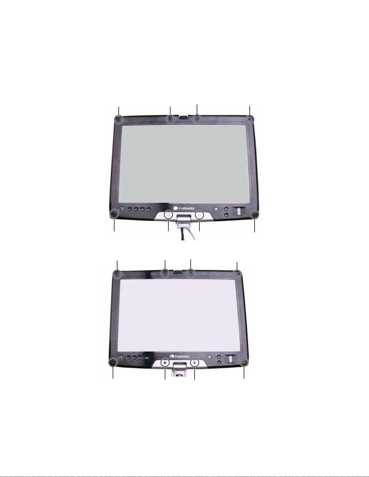
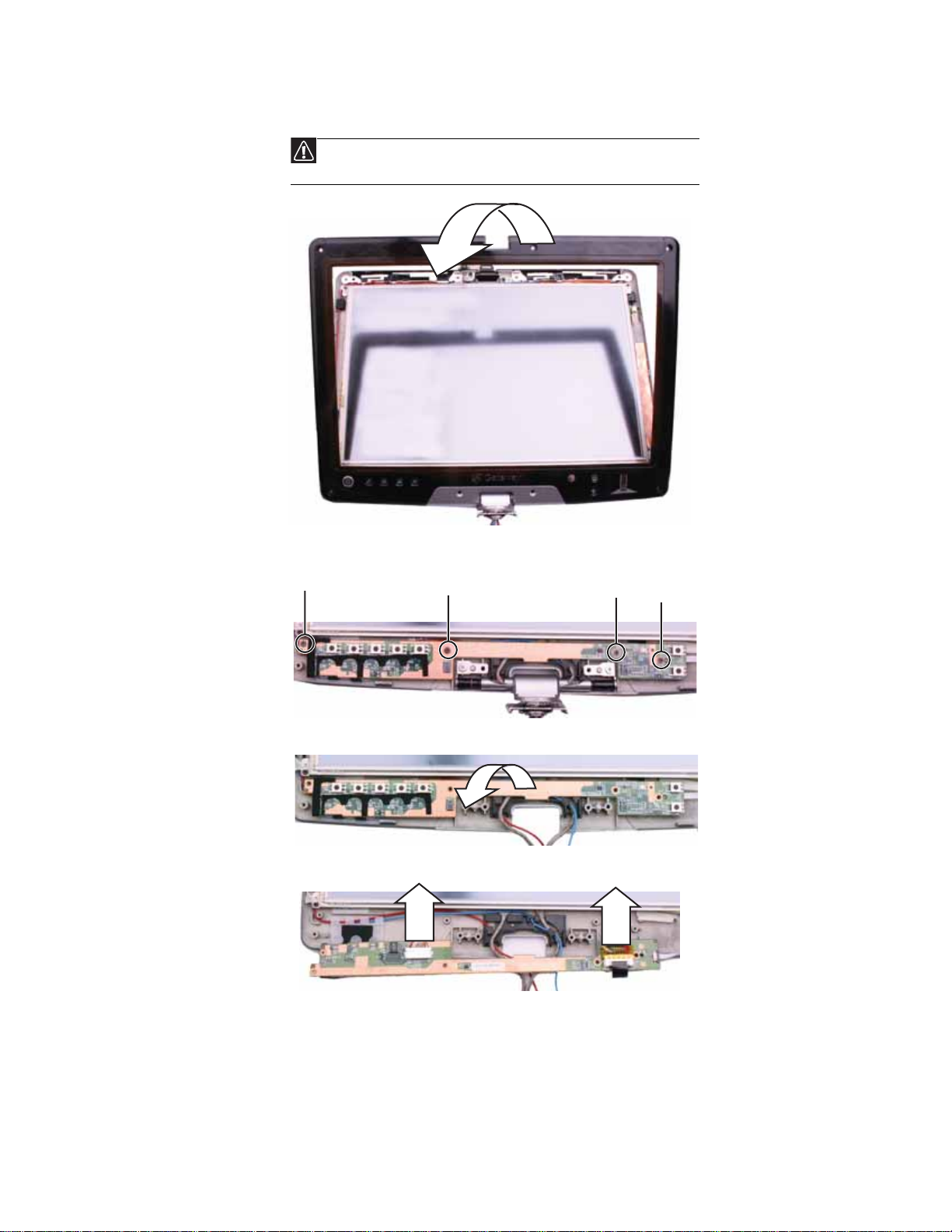
10 Remove the six black and tw o sil v er ru bber inser ts f r om t he f r ont of the LCD panel assembly.
Rubber insert
Rubber insertRubber insert
Rubber insert
Rubber insert Rubber insert Rubber insert Rubber insert
11 Remove the eight screws from the front of the LCD panel assembly.
Screw
Screw
Screw
Screw
Screw
Screw
Screw
Screw
55

Replacing Convertible Notebook Compon ents
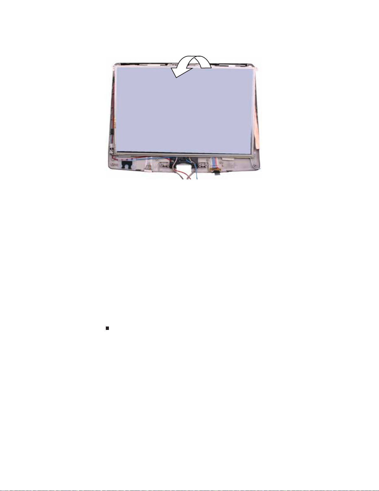
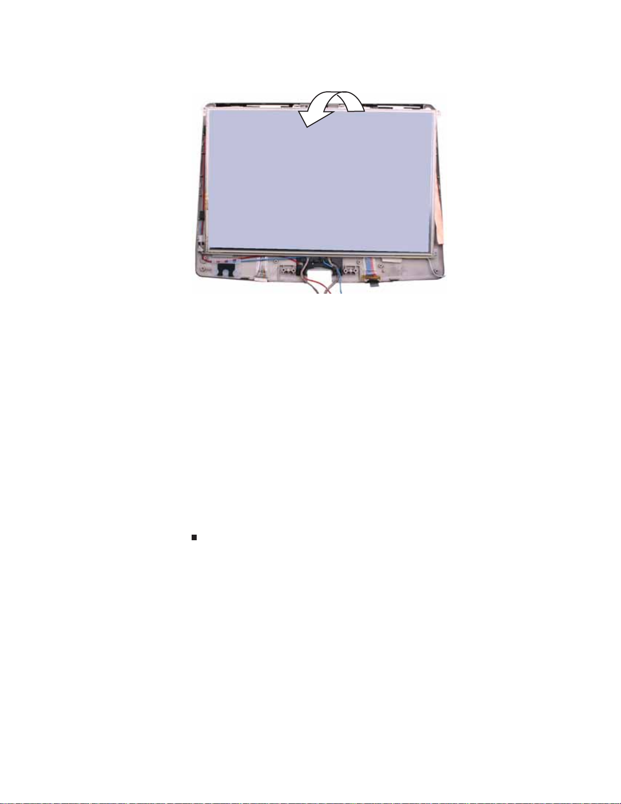
12 Carefully separate the front and back of the LCD panel assembly.
Caution
The fingerprint reader cable connects the two halves. Lay the front of the LCD
panel assembly so you can access the fingerprint cable connector.
13 With a flat-blade screwdriver, scribe, or a fingernail, lift the brown clip off of the fingerprint
cable, then remove the cable. The two halves are now completely separate.
Clip
56

www.gateway.com
14 Remove the two screw s that connect t he f ingerpr int reader to the LCD panel assembly front.
Screw
Screw
15 Lift the b lack bracket off o f the fi ngerpri nt read er.
16 Note the orientation of the old fingerprint reader, then lift it off of the LCD panel assembly
front.
17 Place the new f ingerpr int reader onto the LCD panel assembly front in the same orientation
as the old reader.
57

Replacing Convertible Notebook Compon ents
18 Lay the black bracket on the fingerprint reader, then replace the two screws removed in
Step 14.
19 Make sure the brown fingerprint reader cable connector clip is in the raised position, then
insert the cable into the connector and lower the clip onto the cable.
Important
The cable is correctly oriented if it is not twisted.
20 Press the two halves of the LCD panel front and back together in several places un til they
click in place. You should find no loose spots or spots where the two halves do not meet.
21 Repl ace the eight LCD panel assem bly screws removed in Step 11.
22 Replac e the ei ght rub ber i nserts re moved in Step 10.
23 Replace the LCD assembly by follow ing the steps in “Replacing the L CD a ss embly” on page51.
24 Replace the system board by following the steps in “Replaci ng the s y stem boar d” on page35.
25 Replace the palm rest by following the steps in “Replacing the palm rest” on page25.
26 Replace the hinge cover by following the steps in “Replacing the hinge cover” on page 23.
27 Replace the hard drive by following the steps in “Replacing the hard drive” on page17.
28 Replace the DVD drive by following the steps in “Replacing the DVD drive” on page 14.
29 Reco nn ect the an ten na wi res to th e wi rel ess car d by follo win g th e s teps in “Replacing the
IEEE 802.11 wireless card” on page10.
30 Replace the memory bay cover by following the steps in “Adding or replacing memor y
modules” on page 6.
58

www.gateway.com
Re placing the L CD r otating latc h
v
Tools you need to co mpl ete th is t ask:
Flat-blade driver Scribe or non-marring tool- OR -
Phillips #0 screwdriver
Screws removed during this task:
1 black 2.5*3.0 (DVD
drive)
3 black 2.5*3.0 (Palm
rest-DVD drive bay)
2 black 2.5*3.0 (hard
drive)
3 black 2.5*2.2 (Palm
rest-hard drive bay)
2 black 2.0*6.0 (Palm
rest-bottom)
7 black 2.5*4.5 (Palm
rest-bottom)
3 black 2.5*6.0 (Palm
rest-top)
4 black 2.5*6.0 (LCD
panel hinge)
To replace the LCD rotating latch:
3 black 2.5*4.5 (System
board)
8 black 2.0*3.0 (LCD
assembly)
1 black 2.0*3.0 (LCD
grounding screw)
2 black 2.5*4.5 (LCD
rotating latch)
1 Complete the steps in “Preparing the convertible notebook” on page 5.
2 Remove the mem ory bay cover by following the steps in “Adding or replacing memory
modules” on page 6.
3 Disconnect the wireless antenna wires by following the steps in “Replacing the IEEE 802.11
wireless card” on pag e 10.
4 Remove the DVD drive by following the steps in “Replacing the DVD drive” on page 14.
59

Replacing Convertible Notebook Compon ents
5 Remove the hard drive by following the steps in “Replacing the hard drive” on page 17.
6 Remove the hinge cover by following the steps in “Replacing the hinge cover” on page 23.
7 Remove the palm rest by following the steps in “Replacing the palm rest” on page 25.
8 Remove the s ystem board b y f ollowing the steps in “Replacing the sy stem boar d” on page 35.
9 Remove t he L CD as sembly b y f ollow ing the st eps in “R eplacing the LC D assembly” on page51.
10 Remove the six black and tw o sil v er ru bber inser ts f r om t he f r ont of the LCD panel assembly.
Rubber insert
Rubber insertRubber insert
Rubber insert
Rubber insert Rubber insert Rubber insert Rubber insert
11 Remove the eight screws from the front of the LCD panel assembly.
Screw
Screw
Screw
Screw
Screw
Screw
Screw
Screw
60
www.gateway.com
12 Carefully separate the front and back of the LCD panel assembly.
Caution
The fingerprint reader cable connects the two h alv es. Lay t he fro nt of the L CD
panel assembly beside the back half.
[
Screw
Screw
14 Remove the old LCD rotating latch.
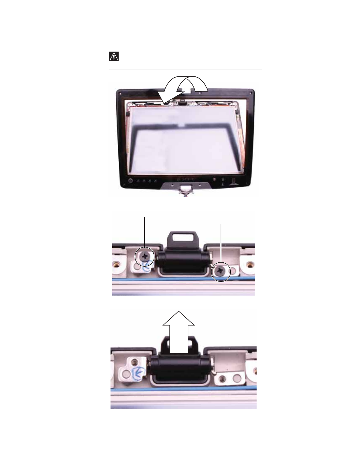
13 Remove the two screws connecting the LCD rotating latch to the LCD lid.
15 Place the new LCD rotating latch into the LCD lid.
61

Replacing Convertible Notebook Compon ents
16 Replace the screws removed in Step13.
17 Press the two halves of the LCD panel front and back together in several places until they
click in place. You should find no loose spots or spots where the two halves do not meet.
18 Repla ce the eight LCD pan el assemb ly screws removed in Step 11.
19 Repl ace th e eigh t rubbe r in serts rem oved in Step 10.
20 Replace the LCD assembly by f ollowing the steps in “Replacing t he L CD a ssembly” on page51 .
21 Replace the s ystem board by f ollowing the steps in “Replacing t he sy st em boar d” on page35.
22 Replace the palm rest by following the steps in “Replacing the palm rest” on page25.
23 Replace the hinge cover by following the steps in “Replacing the hinge cover” on page 23.
24 Replace the hard drive by following the steps in “Replacing the hard drive” on page 17.
25 Replace the DVD drive by following the steps in “Replacing the DVD drive” on page 14.
26 Reco nn ect the an ten na wi res to th e wi rel ess car d by follo win g th e s teps in “Replacing the
IEEE 802.11 wireless card” on page10.
27 Replace the memory bay cover by following the steps in “Adding or replacing memory
modules” on page 6.
62
www.gateway.com
Re placing the L CD hinge
v
Tools you need to co mpl ete th is t ask:
Flat-blade driver Scribe or non-marring tool- OR -
Phillips #0 screwdriver
Screws removed during this task:
1 black 2.5*3.0 (DVD
drive)
3 black 2.5*3.0 (Palm
rest-DVD drive bay)
2 black 2.5*3.0 (hard
drive)
3 black 2.5*2.2 (Palm
rest-hard drive bay)
2 black 2.0*6.0 (Palm
rest-bottom)
7 black 2.5*4.5 (Palm
rest-bottom)
3 black 2.5*6.0 (Palm
rest-top)
4 black 2.5*6.0 (LCD
panel hinge)
To replace the LCD hinge:
3 black 2.5*4.5 (System
board)
8 black 2.0*3.0 (LCD
assembly)
1 black 2.0*3.0 (LCD
grounding screw)
2 chrom e 2. 5*6. 0 (L CD
hinge)
1 Complete the steps in “Preparing the convertible notebook” on page 5.
2 Remove the mem ory bay cover by following the steps in “Adding or replacing memory
modules” on page 6.
3 Disconnect the wireless antenna wires by following the steps in “Replacing the IEEE 802.11
wireless card” on pag e 10.
4 Remove the DVD drive by following the steps in “Replacing the DVD drive” on page 14.
63
Replacing Convertible Notebook Compon ents
5 Remove the hard drive by following the steps in “Replacing the hard drive” on page 17.
6 Remove the hinge cover by following the steps in “Replacing the hinge cover” on page 23.
7 Remove the palm rest by following the steps in “Replacing the palm rest” on page 25.
8 Remove the s ystem board b y f ollowing the steps in “Replacing the sy stem boar d” on page 35.
9 Remove t he L CD as sembly b y f ollow ing the st eps in “R eplacing the LC D assembly” on page51.
10 Remove the six black and tw o sil v er ru bber inser ts f r om t he f r ont of the LCD panel assembly.
Rubber insert
Rubber insertRubber insert
Rubber insert
Rubber insert Rubber insert Rubber insert Rubber insert
11 Remove the eight screws from the front of the LCD panel assembly.
Screw
Screw
Screw
Screw
Screw
Screw
Screw
Screw
64
www.gateway.com
12 Carefully separate the front and back of the LCD panel assembly.
Caution
The fingerprint reader cable connects the two h alv es. Lay t he fro nt of the L CD
panel assembly beside the back half.
[
Screw
Screw
13 Remove the two screws connecting the LCD hinge to the LCD lid.
65
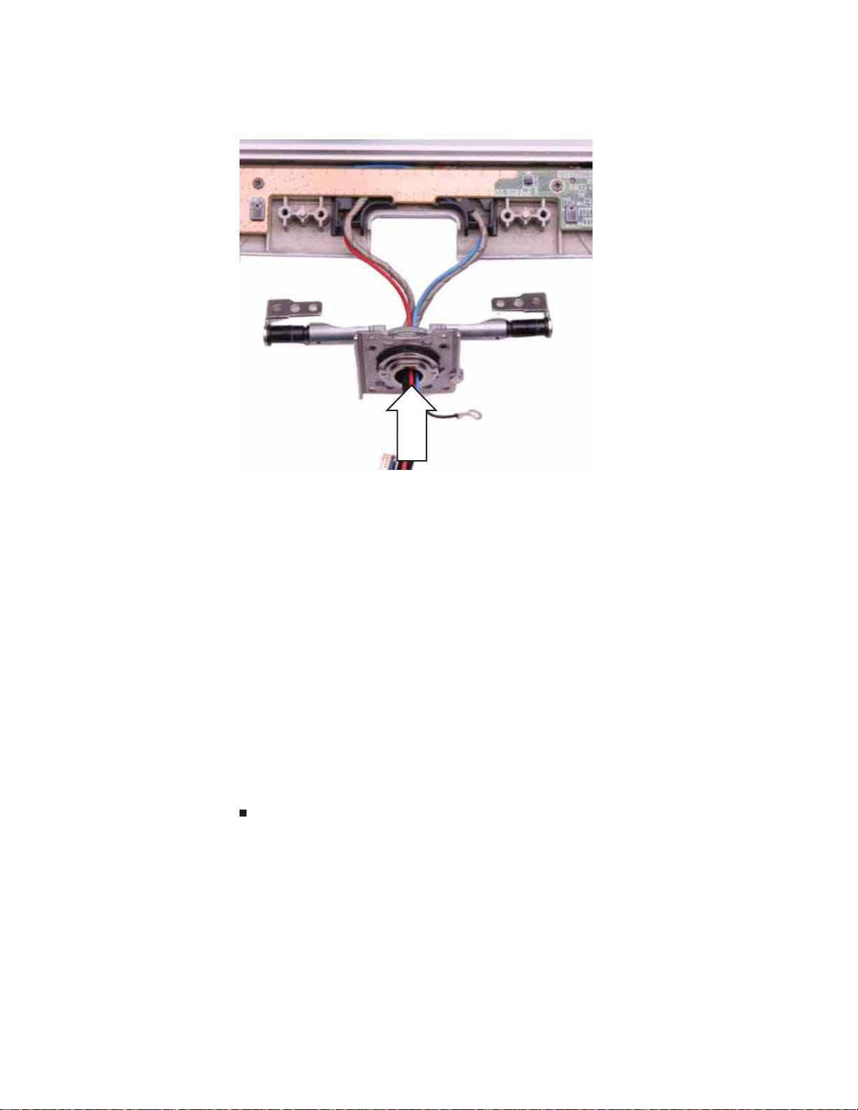
Replacing Convertible Notebook Compon ents
14 Remo v e t he old LCD hinge. Be careful to feed each cable individual l y thr ough the hinge , w ith
the grey LCD cable last.
15 Feed the cables through the new LCD hinge, with the grey LCD cable first.
16 Place the new LCD hinge into the LCD lid.
17 Replace the screws removed in Step 13.
18 Press the two halves of the LCD panel front and back together in several places until they
click in place. You should find no loose spots or spots where the two halves do not meet.
19 Repl ace the eight LCD panel assem bly screws removed in Step 11.
20 Replace the eigh t rubb er in serts rem oved in Step 10.
21 Replace the L CD as sembly by follow ing the steps in “Replacing the LCD assembly” on page51.
22 Replace the system board by following the steps in “Replacing t he sy st em board” o n page35.
23 Replace the palm rest by following the steps in “Replacing the palm rest” on page25.
24 Replace the hinge cover by following the steps in “Replacing the hinge cover” on page 23.
25 Replace the hard drive by following the steps in “Replacing the hard drive” on page 17.
26 Replace the DVD drive by following the steps in “Replacing the DVD drive” on page 14.
27 Rec onn ect th e an ten na w ires to th e w ire less ca rd by foll owin g t he step s i n “Replacing the
IEEE 802.11 wireless card” on page10.
28 Replace the memory bay cover by following the steps in “Adding or replacing memor y
modules” on page 6.
66
www.gateway.com
Re placing the indicat or/butt on board
v
Tools you need to co mpl ete th is t ask:
Flat-blade driver Scribe or non-marring tool- OR -
Phillips #0 screwdriver
Screws removed during this task:
1 black 2.5*3.0 (DVD
drive)
3 black 2.5*3.0 (Palm
rest-DVD drive bay)
2 black 2.5*3.0 (hard
drive)
3 black 2.5*2.2 (Palm
rest-hard drive bay)
2 black 2.0*6.0 (Palm
rest-bottom)
7 black 2.5*4.5 (Palm
rest-bottom)
3 black 2.5*6.0 (Palm
rest-top)
4 black 2.5*6.0 (LCD
panel hinge)
To replace the indicator/button board:
3 black 2.5*4.5 (System
board)
8 black 2.0*3.0 (LCD
assembly)
1 black 2.0*3.0 (LCD
grounding screw)
4 black 2.0*3.0
(indicator/button board)
1 Complete the steps in “Preparing the convertible notebook” on page 5.
2 Remove the mem ory bay cover by following the steps in “Adding or replacing memory
modules” on page 6.
3 Disconnect the wireless antenna wires by following the steps in “Replacing the IEEE 802.11
wireless card” on pag e 10.
4 Remove the DVD drive by following the steps in “Replacing the DVD drive” on page 14.
67

Replacing Convertible Notebook Compon ents
5 Remove the hard drive by following the steps in “Replacing the hard drive” on page 17.
6 Remove the hinge cover by following the steps in “Replacing the hinge cover” on page 23.
7 Remove the palm rest by following the steps in “Replacing the palm rest” on page 25.
8 Remove the s ystem board b y f ollowing the steps in “Replacing the sy stem boar d” on page 35.
9 Remove t he L CD as sembly b y f ollow ing the st eps in “R eplacing the LC D assembly” on page51.
10 Remove the six black and tw o sil v er ru bber inser ts f r om t he f r ont of the LCD panel assembly.
Rubber insert
Rubber insertRubber insert
Rubber insert
Rubber insert Rubber insert Rubber insert Rubber insert
11 Remove the eight screws from the front of the LCD panel assembly.
Screw
Screw
Screw
Screw
Screw
Screw
Screw
Screw
68
www.gateway.com
12 Carefully separate the front and back of the LCD panel assembly.
Caution
The fingerprint reader cable connects the two h alv es. Lay t he fro nt of the L CD
panel assembly beside the back half.
13 Remove the four screws that connect the indicator/button board to the LCD panel assembly
back.
Screw
Screw
Screw
Screw
14 Lift the indicator/button board off of the LCD panel assembly back, then turn it over.
15 Disconnect the two cables from the old indicator/button board.
16 Connect the two cables to the new indicator/button board.
17 Replace the indicator/button board, then replace the four screws removed in Step13.
18 Press the two halves of the LCD panel front and back together in several places until they
click in place. You should find no loose spots or spots where the two halves do not meet.
19 Repl ace the eight LCD panel assem bly screws removed in Step 11.
20 Replace the eigh t rubb er in serts rem oved in Step 10.
69

Replacing Convertible Notebook Compon ents
21 Replace the L CD as sembly by follow ing the steps in “Replacing the LCD assembly” on page51.
22 Replace the system board by following the steps in “Replacing t he sy st em board” o n page35.
23 Replace the palm rest by following the steps in “Replacing the palm rest” on page25.
24 Replace the hinge cover by following the steps in “Replacing the hinge cover” on page 23.
25 Replace the hard drive by following the steps in “Replacing the hard drive” on page 17.
26 Replace the DVD drive by following the steps in “Replacing the DVD drive” on page 14.
27 Rec onn ect th e an ten na w ires to th e w ire less ca rd by foll owin g t he step s i n “Replacing the
IEEE 802.11 wireless card” on page10.
28 Replace the memory bay cover by following the steps in “Adding or replacing memor y
modules” on page 6.
70

Re placing the in ver ter
www.gateway.com
v
Tools you need to co mpl ete th is t ask:
Flat-blade driver Scribe or non-marring tool- OR -
Phillips #0 screwdriver
Screws removed during this task:
1 black 2.5*3.0 (DVD
drive)
3 black 2.5*3.0 (Palm
rest-DVD drive bay)
2 black 2.5*3.0 (hard
drive)
3 black 2.5*2.2 (Palm
rest-hard drive bay)
2 black 2.0*6.0 (Palm
rest-bottom)
7 black 2.5*4.5 (Palm
rest-bottom)
3 black 2.5*6.0 (Palm
rest-top)
4 black 2.5*6.0 (LCD
panel hinge)
To replace the inverter:
3 black 2.5*4.5 (System
board)
8 black 2.0*3.0 (LCD
assembly)
1 black 2.0*3.0 (LCD
grounding screw)
1 Complete the steps in “Preparing the convertible notebook” on page 5.
2 Remove the mem ory bay cover by following the steps in “Adding or replacing memory
modules” on page 6.
3 Disconnect the wireless antenna wires by following the steps in “Replacing the IEEE 802.11
wireless card” on pag e 10.
4 Remove the DVD drive by following the steps in “Replacing the DVD drive” on page 14.
71

Replacing Convertible Notebook Compon ents
5 Remove the hard drive by following the steps in “Replacing the hard drive” on page 17.
6 Remove the hinge cover by following the steps in “Replacing the hinge cover” on page 23.
7 Remove the palm rest by following the steps in “Replacing the palm rest” on page 25.
8 Remove the s ystem board b y f ollowing the steps in “Replacing the sy stem boar d” on page 35.
9 Remove t he L CD as sembly b y f ollow ing the st eps in “R eplacing the LC D assembly” on page51.
10 Remove the six black and tw o sil v er ru bber inser ts f r om t he f r ont of the LCD panel assembly.
Rubber insert
Rubber insertRubber insert
Rubber insert
Rubber insert Rubber insert Rubber insert Rubber insert
11 Remove the eight screws from the front of the LCD panel assembly.
Screw
Screw
Screw
Screw
Screw
Screw
Screw
Screw
72

www.gateway.com
12 Carefully separate the front and back of the LCD panel assembly.
Caution
The fingerprint reader cable connects the two h alv es. Lay t he fro nt of the L CD
panel assembly beside the back half.
13 Disconnect the two cables from the old inverter.
14 Remove the old inverter from the LCD assembly back.
15 Conne ct the two ca bles to th e new inverter.
16 Replace the inverter.
17 Press the two halves of the LCD panel front and back together in several places until they
click in place. You should find no loose spots or spots where the two halves do not meet.
18 Repla ce the eight LCD pan el assemb ly screws removed in Step 11.
19 Repl ace th e eigh t rubbe r in serts rem oved in Step 10.
20 Replace the LCD assembly by f ollowing the steps in “Replacing t he L CD a ssembly” on page51 .
21 Replace the s ystem board by f ollowing the steps in “Replacing t he sy st em board” o n page35.
22 Replace the palm rest by following the steps in “Replacing the palm rest” on page25.
23 Replace the hinge cover by following the steps in “Replacing the hinge cover” on page 23.
24 Replace the hard drive by following the steps in “Replacing the hard drive” on page 17.
25 Replace the DVD drive by following the steps in “Replacing the DVD drive” on page 14.
26 Reco nn ect the an ten na wi res to th e wi rel ess car d by follo win g th e s teps in “Replacing the
IEEE 802.11 wireless card” on page10.
27 Replace the memory b ay cover by foll owing the steps in “Adding or replacing memor y
modules” on page 6.
73

Replacing Convertible Notebook Compon ents
Re placing the L CD panel
v
Tools you need to co mpl ete th is t ask:
Flat-blade driver Scribe or non-marring tool- OR -
Phillips #0 screwdriver
Screws removed during this task:
1 black 2.5*3.0 (DVD
drive)
3 black 2.5*3.0 (Palm
rest-DVD drive bay)
2 black 2.5*3.0 (hard
drive)
3 black 2.5*2.2 (Palm
rest-hard drive bay)
2 black 2.0*6.0 (Palm
rest-bottom)
7 black 2.5*4.5 (Palm
rest-bottom)
74
3 black 2.5*6.0 (Palm
rest-top)
4 black 2.5*6.0 (LCD
panel hinge)
4 black 2.0*3.0 (LCD
panel)
3 black 2.5*4.5 (System
board)
8 black 2.0*3.0 (LCD
assembly)
1 black 2.0*3.0 (LCD
grounding screw)
4 black 2.0*3.0
(indicator/button board)

www.gateway.com
To replace the LCD panel:
1 Complete the steps in “Preparing the convertible notebook” on page 5.
2 Remove the mem ory bay cover by following the steps in “Adding or replacing memory
modules” on page 6.
3 Disconnect the wireless antenna wires by following the steps in “Replacing the IEEE 802.11
wireless card” on pag e 10.
4 Remove the DVD drive by following the steps in “Replacing the DVD drive” on page 14.
5 Remove the hard drive by following the steps in “Replacing the hard drive” on page 17.
6 Remove the hinge cover by following the steps in “Repl acing the hinge cover” on page 23.
7 Remove the palm rest by following the steps in “Replacing the palm rest” on page 25.
8 Remove the s ystem board b y f ollowing the steps in “Replacing the sy stem boar d” on page 35.
9 Remove t he L CD as sembly b y f ollow ing the st eps in “R eplacing the LC D assembly” on page51.
10 Disconnect the fingerprint cable by following the instructions in “Replacing the fingerprint
read er ” o n pag e 5 4.
11 Remove the indicator/button board by following the instructions in “Replacin g the
indicator/button board” on page 67.
12 Remove the inverter by following the instructions in “Replacing the inverter” on page71.
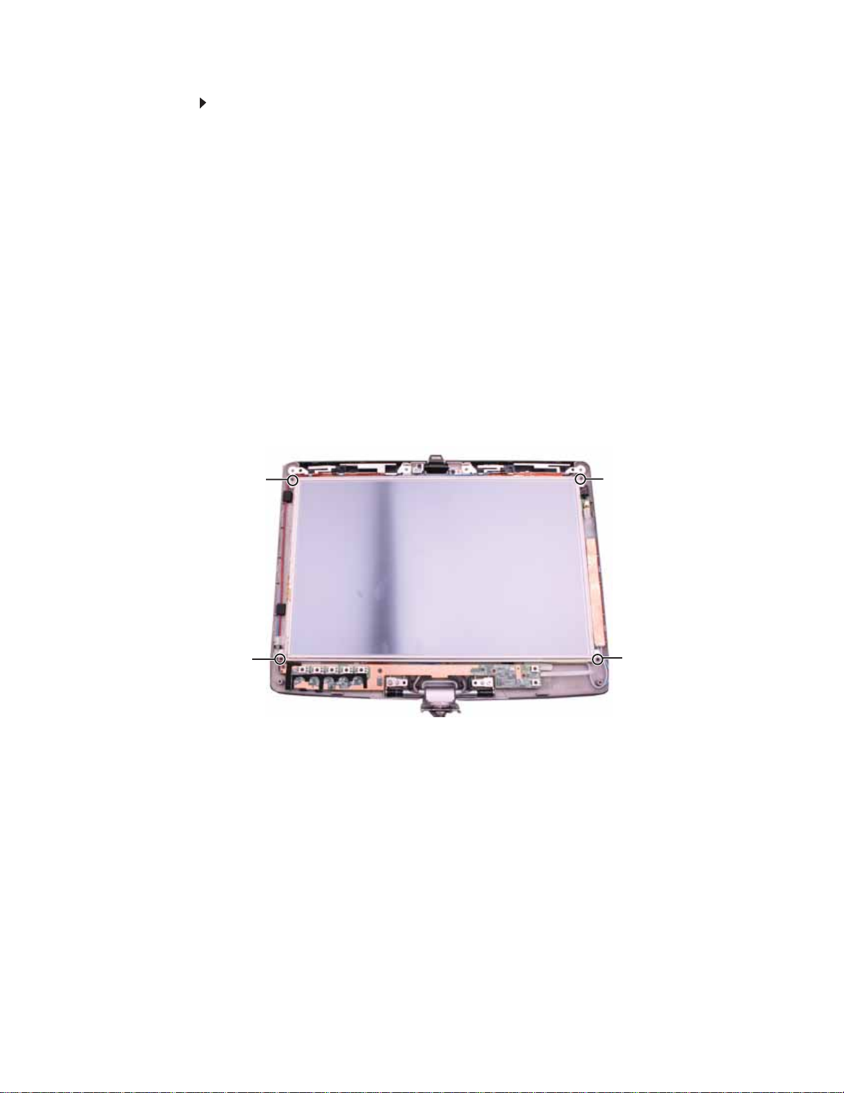
13 Remove the four screws connecting the LCD panel to the LCD lid.
Screw
Screw
Screw
Screw
75
Replacing Convertible Notebook Compon ents
14 Remove the old LCD panel from the LCD lid.
15 Place the new LCD panel into the LCD lid.
16 Replace the screws removed in Step13.
17 Replace the inverter by following the inst ructions in “Replacing the inverter” on page71.
18 Repla ce the ind icator/button b oard by following the i nstruction s in “Replacing the
indicator/button board” on page 67.
19 Connect the fingerprint cable by following the instructions in “Replacing the fingerprint
read er ” o n pag e 5 4.
20 Replace the LCD assembly by f ollowing the steps in “Replacing t he L CD a ssembly” on page51 .
21 Replace the s ystem board by f ollowing the steps in “Replacing t he sy st em boar d” on page35.
22 Replace the palm rest by following the steps in “Replacing the palm rest” on page25.
23 Replace the hinge cover by following the steps in “Replacing the hinge cover” on page 23.
24 Replace the hard drive by following the steps in “Replacing the hard drive” on page 17.
25 Replace the DVD drive by following the steps in “Replacing the DVD drive” on page 14.
26 Reco nn ect the an ten na wi res to th e wi rel ess car d by follo win g th e s teps in “Replacing the
IEEE 802.11 wireless card” on page10.
27 Replace the memory bay cover by following the steps in “Adding or replacing memory
modules” on page 6.
76
www.gateway.com
Re placing the L CD a ssembl y lid
v
Tools you need to co mpl ete th is t ask:
Flat-blade driver Scribe or non-marring tool- OR -
Phillips #0 screwdriver
Screws removed during this task:
1 black 2.5*3.0 (DVD
drive)
3 black 2.5*3.0 (Palm
rest-DVD drive bay)
2 black 2.5*3.0 (hard
drive)
3 black 2.5*2.2 (Palm
rest-hard drive bay)
2 black 2.0*6.0 (Palm
rest-bottom)
7 black 2.5*4.5 (Palm
rest-bottom)
3 black 2.5*6.0 (Palm
rest-top)
4 black 2.5*6.0 (LCD
panel hinge)
4 black 2.0*3.0 (LCD
panel)
3 black 2.5*4.5 (System
board)
8 black 2.0*3.0 (LCD
assembly)
1 black 2.0*3.0 (LCD
grounding screw)
4 black 2.0*3.0
(indicator/button board)
77
Replacing Convertible Notebook Compon ents
To replace the LCD assembly lid:
1 Complete the steps in “Preparing the convertible notebook” on page 5.
2 Remove the mem ory bay cover by following the steps in “Adding or replacing memory
modules” on page 6.
3 Disc on nect the wire less ante nn a wire s by fol lowi ng th e s teps in “Replacing the IEEE 802.11
wireless card” on pag e 10.
4 Remove the DVD drive by following the steps in “Replacing the DVD drive” on page 14.
5 Remove the hard drive by following the steps in “Replacing the hard drive” on page 17.
6 Remove the hinge cover by following the steps in “Replacing the hinge cover” on page 23.
7 Remove the palm rest by following the steps in “Replacing the palm rest” on page 25.
8 Remove the s ystem board b y f ollowing the steps in “Replacing the sy stem boar d” on page 35.
9 Remove t he L CD as sembly b y f ollow ing the st eps in “R eplacing the LC D assembly” on page51.
10 Disconnect the fingerprint cable by following the instructions in “Replacing the fingerprint
read er ” o n pag e 5 4.
11 Remove the indicator/button board by following the instructions in “Replacin g the
indicator/button board” on page 67.
12 Remove the inverter by following the instructions in “Replacing the inverter” on page71.
13 Remove the four screws connecting the LCD panel to the LCD lid.
Screw
Screw
Screw
Screw
78
www.gateway.com
14 Remove the LCD panel from the old LCD lid.
15 Place the LCD panel into the new LCD lid.
16 Replace the screws removed in Step13.
17 Replace the inverter by following the inst ructions in “Replacing the inverter” on page71.
18 Replac e the indi cator/button b oard by following the i nstruction s in “Replacing the
indicator/button board” on page 67.
19 Connect the fingerprint cable by following the instructions in “Replacing the fingerprint
read er ” o n pag e 5 4.
20 Replace the LCD assembly by f ollowing the steps in “Replacing t he L CD a ssembly” on page51 .
21 Replace the s ystem board by f ollowing the steps in “Replacing t he sy st em board” o n page35.
22 Replace the palm rest by following the steps in “Replacing the palm rest” on page25.
23 Replace the hinge cover by following the steps in “Replacing the hinge cover” on page 23.
24 Replace the hard drive by following the steps in “Replacing the hard drive” on page 17.
25 Replace the DVD drive by following the steps in “Replacing the DVD drive” on page 14.
26 Reco nn ect the an ten na wi res to th e wi rel ess car d by follo win g th e s teps in “Replacing the
IEEE 802.11 wireless card” on page10.
27 Replace the memory b ay cover by foll owing the steps in “Adding or replacing memor y
modules” on page 6.
Copyright
© 2007 Gateway, Inc. All rights reserved. Gateway, Gateway Country, the Gateway stylized logo,
and the black-and-white spot design are trademarks or registered trademarks of Gateway, Inc. in
the United States and other countries. All other brands and product names are trademarks or
registered trademarks of their respective companies.
79

Replacing Convertible Notebook Compon ents
80


MAN PHOENIX SVC GDE R0 4/07
 Loading...