

Page 1

Gateway® Server Baseboard Management
Controller (BMC)
USERGUIDE
®
Page 2

Page 3

Contents
Introduction . . . . . . . . . . . . . . . . . . . . . . . . . . . . . . . . . . . . . . . . . . . . . . . . . . . . . . . . 1
Features and operation of the BMC server . . . . . . . . . . . . . . . . . . . . . . . . . . . . . . . 1
Using virtual storage . . . . . . . . . . . . . . . . . . . . . . . . . . . . . . . . . . . . . . . . . . . . . . . . 21
Notices . . . . . . . . . . . . . . . . . . . . . . . . . . . . . . . . . . . . . . . . . . . . . . . . . . . . . . . . . . . 31
Starting the BMC Web interface . . . . . . . . . . . . . . . . . . . . . . . . . . . . . . . . . . 1
Connecting to the BMC Web interface through a Web browser . . . . . 1
Viewing the hardware inventory . . . . . . . . . . . . . . . . . . . . . . . . . . . . . . 2
Setting power control options . . . . . . . . . . . . . . . . . . . . . . . . . . . . . . . . 3
Monitoring sensors and setting PEFs (platform event flags) . . . . . . . . 4
Managing the system event log . . . . . . . . . . . . . . . . . . . . . . . . . . . . . . . 5
Setting the Watchdog Timer . . . . . . . . . . . . . . . . . . . . . . . . . . . . . . . . . . 6
Managing network settings . . . . . . . . . . . . . . . . . . . . . . . . . . . . . . . . . . 7
Configuring platform event traps . . . . . . . . . . . . . . . . . . . . . . . . . . . . . 8
Configuring for multiple users . . . . . . . . . . . . . . . . . . . . . . . . . . . . . . . 10
Connecting to the Remote KVMS Java Client . . . . . . . . . . . . . . . . . . . . . . . 11
Optimizing the mouse settings . . . . . . . . . . . . . . . . . . . . . . . . . . . . . . 12
Reentering your application license key (optional) . . . . . . . . . . . . . . . 16
Using the Remote KVMS Java Client window controls . . . . . . . . . . . . . . . 17
Menu Options . . . . . . . . . . . . . . . . . . . . . . . . . . . . . . . . . . . . . . . . . . . . 17
System buttons . . . . . . . . . . . . . . . . . . . . . . . . . . . . . . . . . . . . . . . . . . . . . . 21
Connecting a local storage device . . . . . . . . . . . . . . . . . . . . . . . . . . . . . . . 22
Remote Storage Server . . . . . . . . . . . . . . . . . . . . . . . . . . . . . . . . . . . . . . . . 25
Booting the BMC host server from a connected Virtual Storage device . 29
i
Page 4

Contents
ii
Page 5

www.gateway.com
Introduction
The following information will help you connect with the BMC and understand and utilize its
features, including the Remote KVMS.
Features and operation of the BMC server
Starting the BMC Web interface
You can connect to the BMC Web interface through a Web browser.
Connecting to the BMC Web interface through a Web browser
To connect to the BMC Web interface:
1 Open a Web browser and go to the current IP address of the BMC Web interface (default
http://192.168.2.100).
2 When you are prompted to enter Username and Password, enter the following values:
Username: admin and Password: admin
1
Page 6
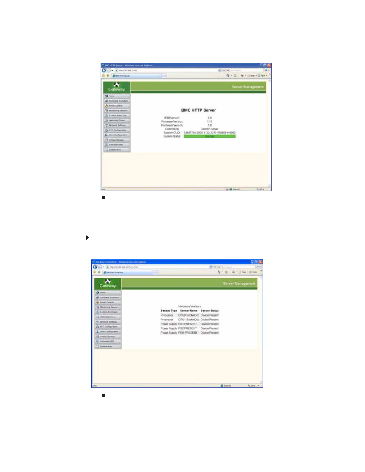
3 After entering the username and password, click OK. The BMC HTTP Server interface screen
opens.
Viewing the hardware inventory
The hardware inventory provides you with information on the CPU and power supply
configuration of the BMC host server.
To access the hardware inventory:
• From the BMC Web server main screen, click Hardware Inventory on the left side of the
screen. The Hardware Inventory screen opens.
2
Page 7

www.gateway.com
Setting power control options
The power control options screen provides you with information on the system power status.
It also provides several power control options and lets you set a power restore policy.
The power-on counter indicates the length of time that the BMC (only) has been receiving power
(that is, plugged in) and not how long the server has been turned on. This count takes place
even when the system is powered off. Everything else shown on the screen applies to the BMC
host server and not the BMC itself.
To access the power control options:
1 From the BMC Web server main screen, click Power Control on the left side of the screen.
The Power Control Options screen opens.
2 To change the power control options, open the Power Control Options list and click the
option you prefer. Choose from:
• Power Up - The system is started from powered off status.
• Power Cycle - The system is shut down, then powered up again after a brief pause
(a cold reboot).
• Hard Reset - A warm reboot (like pressing the reset button).
• Power Down - The system is turned off.
• Force Dump - This causes the operating system to dump core. Support for this option
depends on the operating system.
To locate the server, turn on the UID (chassis locator), which turns on the ID LED on the
host chassis.
To set a power restore policy, click the option you prefer.
3
Page 8

Monitoring sensors and setting PEFs (platform event flags)
The monitoring sensors screen provides you with information on the status of the various sensors
in the server being monitored. You can set a particular sensor’s PEF configuration to initiate a
specific action, as you designate.
To access the monitoring sensors and set PEFs:
1 From the BMC Web server main screen, click Monitoring Sensors on the left side of the
screen. The Monitoring Sensors screen opens.
Important
If this screen has been open for any length of time, you must refresh the
screen to get current readings.
The color on the left side of the column indicates the status of the sensor:
• Green—Normal
• Red—Abnormal
2 To change the PEF configuration for an individual sensor, click PEF for the sensor you want
to set. The PEF Configuration screen for that sensor opens.
4
Page 9

www.gateway.com
Each sensor has an operating range. When a sensor changes state (from healthy to
unhealthy, or unhealthy to healthy), you can choose to initiate some type of action. The
PEF configuration screen shows all possible sensor states for that sensor (only states
applicable to this sensor are available). You can choose to have the server take a variety
of actions (from shut-down to a notifying e-mail), depending on the change of state. Only
one action can be enabled for all the events selected.
3 Click the check box of any event that you want to trigger an action, then choose the action
from the drop-down list. Do not select the OEM action, which is reserved for system use.
Global PEF enable must also be turned on for any action to be initiated. Also, the action
must be enabled on the Platform Event Trap (PET) screen (see “Configuring platform event
traps” on page 8).
The Current PEF Entries table shows information for all sensors with PEF configurations
set. It lets you enable, disable, or delete the configuration for any sensor’s PEF.
For notifications to take place, the appropriate Alert Policy must be selected from the list
at the bottom of the page. Alert Policies must be configured on the PET Configuration page
(see “Configuring platform event traps” on page 8)
4 Change the settings as appropriate, then click Monitoring Sensors to return to the
Monitoring Sensors screen.
Managing the system event log
The system event log screen lets you review sensor status change history or clear the system
event log. The system event log provides information such as Event Type, Date, Time, Source,
Description, and Direction (change from last sensor reading).
To access the system event log:
• From the BMC Web server main screen, click System Event Log on the left side of the
screen. The System Event Log screen opens.
To clear the event log (history), click Clear Event Log.
5
Page 10
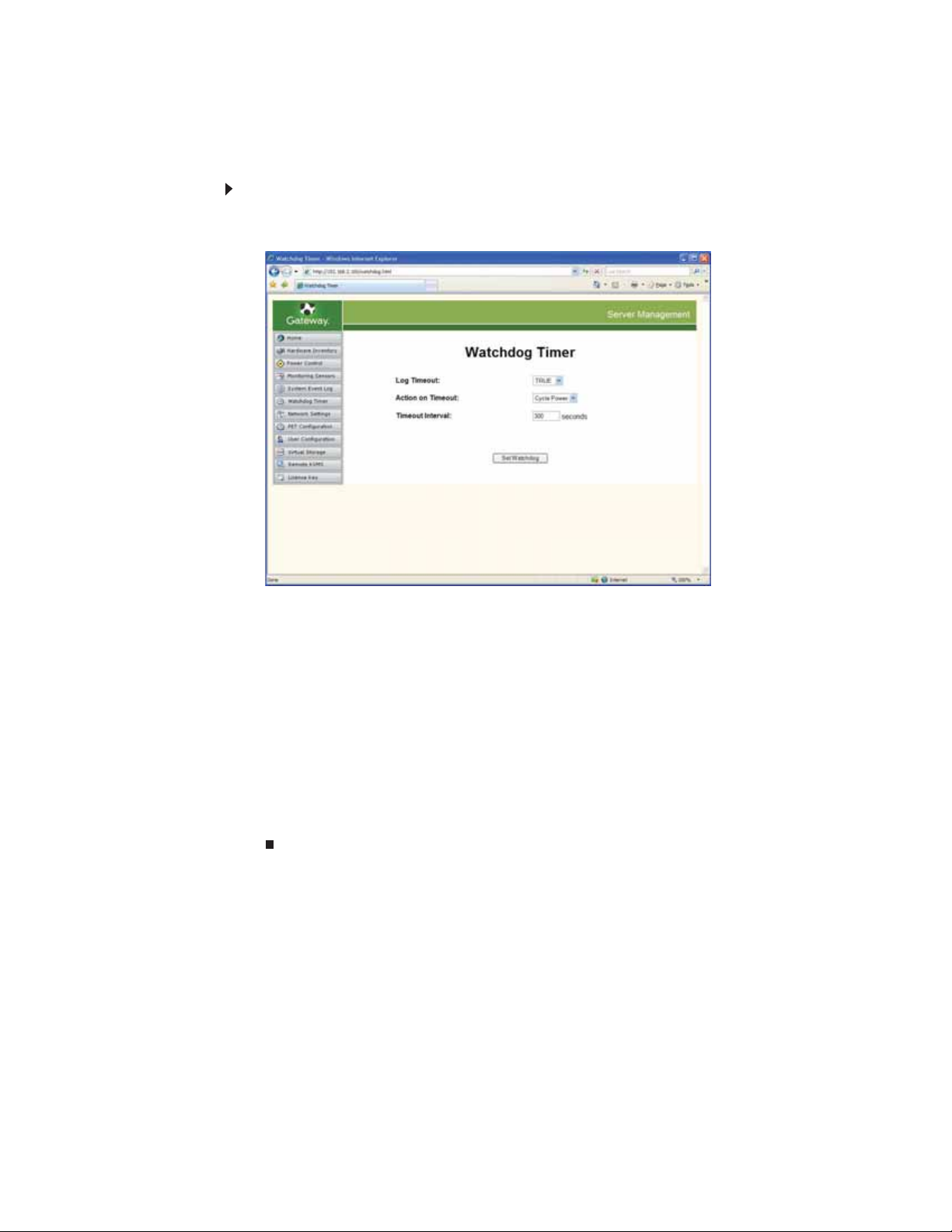
Setting the Watchdog Timer
The Watchdog Timer restarts your server, turns off your server, or cycles power to your server
in your absence. If any event hangs the server, the Watchdog Timer takes the action you set.
To set the Watchdog Timer:
1 From the BMC Web server main screen, click Watchdog Timer on the left side of the screen.
The Watchdog Timer screen opens.
2 Open the Log Timeout list, then select an option.
• True—Logs the timeout.
• False—Does not log the timeout.
3 Open the Action on Timeout list, then set the action on timeout.
• No Action—No action is taken.
• Hard reset—A warm reboot (like pressing the reset button).
• Power down—The system is turned off.
• Cycle power—The system is shut down, then powered up again after a brief pause
(a cold reboot).
4 Click Timeout Interval to set the interval after a hang, before the Action on Timeout is
triggered. The default interval is 300 seconds.
5 Click Set Watchdog to set the Watchdog Timer.
6
Page 11

www.gateway.com
Managing network settings
The network settings screen lets you review or change the current network settings of the BMC
LAN interface to which you are connected. It also provides you with the MAC address of the BMC
LAN.
The BMC can be configured either to use a dynamic IP address through DHCP, or a specified
static IP address (recommended). For DHCP, click the DHCP enable check box. For a static IP
configuration, populate the three IP fields on this page. You may need to check with your LAN
administrator to verify your settings.
To view or change the network settings:
1 From the BMC Web server main screen, click Network Settings on the left side of the
screen. The Network Settings screen opens with the BMC LAN’s current settings shown.
2 Click the DHCP box.
- OR -
Enter the IP Address (default is 192.168.2.100), the Subnet Mask, and the Gateway. For
information, contact your network administrator.
Note: If the IP address has been changed, or DHCP has been enabled, you will immediately
lose your connection when you click Apply. The next time you log in, you must use the
new IP Address.
7
Page 12
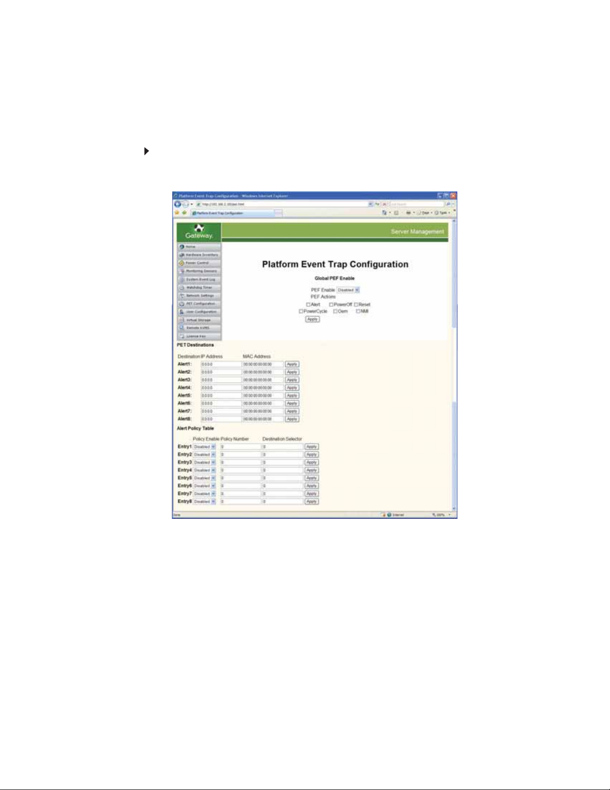
Configuring platform event traps
The Platform Event Trap Configuration screen lets you configure platform event traps and set
up notifications when the policies are triggered. Any PEF action that you want to allow a sensor
to trigger must be checked, then you must click Apply. For information on configuring individual
sensor’s PEFs (platform event flags), see “Monitoring sensors and setting PEFs (platform event
flags)” on page 4.
To configure the platform event trap:
1 From the BMC Web server main screen, click PET Configuration on the left side of the
screen. The Platform Event Trap Configuration screen opens.
8
2 Select Enabled in the PEF Enable list.
3 Click the check box of any action that you want the sensors to trigger. Click Apply. Options
are:
• Alert—To send an alert notification to an alert destination (see below).
• PowerOff—To turn off the power to the server.
• Reset—To do a warm reboot of the server (like pressing the Reset button).
• PowerCycle—To turn off the power to the server, then turn it back on.
• OEM—Do not select (reserved for system use).
• NMI—Causes the operating system to dump core.
4 Under PET Destinations, enter both the Destination IP Address and the MAC Address
for every SNMP management station to which you want notifications sent, then click Apply
for each.
Page 13

www.gateway.com
5 The Alert Policy Table lets you group alert destinations. In this table, alert destinations are
placed into the Destination Selector fields and group numbers are placed into the Policy
Number fields. For example, if group policy 1 is selected, alerts are sent to both alert
destinations 1 and 2. If group policy 2 is selected, an alert is only sent to alert destination
1, and so forth.
After configuring Alert Policy Groups, return to the Monitoring Sensors page (see
“Monitoring sensors and setting PEFs (platform event flags)” on page 4), then:
a Choose a sensor that you want to trigger an SNMP alert (by clicking the sensor’s PEF
button).
b Select Send Alert for the PEF Action.
c Enable the PEF Control by selecting Enabled from the list.
d Choose the appropriate Alert Policy Group from the drop down list, then click Add.
In this illustration you can choose No Alert Policy, Alert Policy 1, Alert Policy 2,
Alert Policy 3, or Alert Policy 4.
9
Page 14

Configuring for multiple users
The user configuration screen lets you configure the server for multiple users, including setting
up passwords and privileges.
We recommend that you delete or change all default passwords and unused user names.
To configure multiple users:
1 From the BMC Web server main screen, click User Configuration on the left side of the
screen. The User Configuration screen opens.
2 Assign a User Name and a Password Size (16- or 20-byte), then enter a Password (IPMI
v1.5 only supports 16 byte passwords).
3 Reenter the password to confirm, then set the User Privilege level from the list. Each
privilege level includes all the privileges from the level below it:
• Administrator–Allowed to activate and configure the BMC, and access the Remote
KVMS features.
• Operator–Allowed to power the system on and off, view logs, and clear logs.
• User–Only allowed to view basic system status.
• OEM—Do not select (reserved for system use).
4 Click Set to enter your settings.
10
Page 15

www.gateway.com
Connecting to the Remote KVMS Java Client
Important
To successfully run the Remote KVMS Java Client, you should have a Java Runtime
Environment (we recommend the latest version) installed in your computer. This is available
at http://www.java.com/en/download/index.jsp
When the Remote KVMS button in the BMC Web interface is clicked, a new Remote KVMS
Viewer window opens.
To connect to the Remote KVMS Java Client:
• From the BMC HTTP Server interface screen, click Remote KVMS. The Remote KVMS Viewer
window opens and you are connected to the BMC Web server.
.
Important
If you change the URL of the Web browser, Remote KVMS Java Client will
be disconnected and window will be closed.
Do not click the Refresh button or navigate away from this page until you are
finished.
To ensure the best experience when using your mouse in the Remote KVMS Viewer window,
you must optimize your mouse settings on the BMC’s host server.
11
Page 16

Optimizing the mouse settings
To synchronize the mouse pointer:
• To synchronize the local mouse pointer and the remote mouse pointer, move the local
mouse pointer to the top left corner as shown. This action attracts the remote mouse
pointer to the top left corner of the Remote KVMS Viewer window as well. Both pointers
become synchronized when they overlap as one pointer.
In order to optimize the mouse synchronization, there are some settings that should be
changed from within the KVMS window. Different operating systems have different setups.
(Perform the following steps in the Remote KVMS Viewer window.)
12
Page 17

www.gateway.com
Optimizing the mouse pointer properties in Windows
To optimize the mouse pointer properties:
1 Go to Start, Control Panel, then click Mouse. The Mouse Properties panel opens.
2 Click the Pointer Options tab. The following panel opens.
3 Make sure that the Select a pointer speed bar is set to the middle and that everything
is unchecked. Click OK to continue.
4 Right-click your Windows desktop screen. A menu opens.
5 Click Properties. The Display Properties window opens.
13
Page 18

6 Click the Settings tab, Advanced, then click the TroubleShoot tab.
7 Under Hardware acceleration, set the pointer on the Hardware acceleration bar to one
setting down from full, then click OK.
Optimizing the mouse pointer properties in Linux
To optimize mouse pointer properties in Linux:
1 Use a text editor to edit the file /etc/x11/xorg.conf.
Find this section in the file:
Section “Device”
<some properties>
Driver “mga”
<some more properties>
EndSection
Change it to the following:
Section “Device”
<some properties>
Driver “mga”
Option “noMTRR”
<some more properties>
EndSection
2 Save the changes.
14
Page 19

www.gateway.com
3 For SUSE Linux users:
a Go to N, Control Center, Peripheral, Mouse, then click the Advanced tab. The Mouse
- Control Center window opens.
b Set the Pointer acceleration to 1.0x (min.), then set the Pointer threshold to 20 pixels
(max).
4 For Fedora Core or Red Hat Linux users:
a Open the Mouse Preferences panel.
b Click the Motion tab, then increase the Sensitivity setting, as shown.
c By experimentation, choose an Acceleration setting. To do this, start with an
acceleration setting, synchronize the mouse pointer (see “To synchronize the mouse
pointer:” on page 12), then move the mouse pointer around to test the settings. Repeat
this process until both the local and remote mouse pointers track at identical rates.
Tip
If Windows is running on the local client computer, an Acceleration setting
just below the midpoint seems to work well.
5 Click Close.
15
Page 20

Reentering your application license key (optional)
Your application license key must be entered before you can use the Remote KVMS Java Client.
If you are operating a new server for the first time, you should refer to the Application License
Key document that accompanied your server.
To reenter your application license key:
1 From the BMC Web server main screen, click License Key on the left side of the screen.
The Application License Key screen opens.
2 Enter your application license key, found in an envelope that was included with your server.
3 Click Apply. The License Agreement appears.
4 Accept the terms of the license agreement by clicking OK. Your license key is entered.
16
Page 21

www.gateway.com
Using the Remote KVMS Java Client window controls
The Remote KVMS Viewer window lets you interface directly with the remote server. The
following information describes the various elements of the Remote KVMS Viewer window.
Menu Options
There are three menus: KVMS, Preferences, and Help.
KVMS
Under the KVMS menu, there are 7 different options, including Storage, Keyboard, Refresh
Screen, Take Full Control, Disconnect Session, Relinquish Full Control, and Exit.
• Storage (see “Using virtual storage” on page 21)
17
Page 22

• Virtual Keyboard–The virtual keyboard gives you precise control of keyboard characters
transmitted to the remote server.
• Selecting the Keyboard option opens a Virtual Keyboard (English by default). You
can change the keyboard language in the Preference panel.
• The Lock button is available on all virtual keyboards. Normally, when you click the
HIFT, ALT, CTRL, APPLICATION, and WINDOWS keys, they will remain depressed until
S
clicked again, or until you click a printable character. If you want these keys to remain
depressed, even after you click a printable character, click the L
OCK key.
• Refresh Screen–Clicking Refresh Screen refreshes the content in the Remote KVMS Viewer
window.
• Take Full Control – This option gives you full control of the remote keyboard and mouse.
If there is another user connected, they will be forced to View-only mode.
• Disconnect Session – Lets you disconnect another user who has opened their own Remote
KVMS session. This does not let you disconnect your own session (use Exit).
18
• Relinquish Full Control – Lets you switch from Full Control mode to View-only mode.
• Exit–Clicking Exit closes the Remote KVMS Viewer window and disconnects the active
session.
Page 23

www.gateway.com
Preferences control panel
Accessed by choosing Preferences in the Preferences Menu.
Mouse tab
Clicking the Mouse tab makes the Mouse Mode list available.
The following modes are available on the Mouse Mode list:
• Absolute Mode – Recommended for all sessions, especially when you are connected to
high-latency networks (overlaps local and remote mouse pointers. Mouse tracking is
generally most accurate in this mode.
• Relative Mode (default) – Recommended when Absolute Mode does not operate in a
satisfactory manner (overlaps local and remote mouse pointers).
• Hide Mode (Relative) – Recommended in all other cases (uses Relative Mode tracking and
hides the local mouse pointer to help prevent confusion).
19
Page 24

Keyboard tab
Lets you change the keyboard language to one of 12 available choices. For the virtual keyboard
to function correctly, make sure that the language for both the remote server and local client
computer are set the same. See your operating system documentation for details on changing
your local computer’s keyboard language.
Logging tab
20
There are two fields in this dialog box, including Global Logging and Console Log File, and an
Overwrite Native Library checkbox (do not uncheck this box).
• Global Logging – If you select this option, you can get log messages in a Java Console
or a log file will be generated.
• None – No log messages are generated.
• Console – Log messages are generated in a Java Console window. (See “To view a
log message in a Java Console:” on page 20).
• Log File – Log messages are written to a log file that you create. (See “To specify a
path for the log file:” on page 20)
• Console and Log File – Log messages can either be viewed from a Java Console or
from the existing log file. (See “To view a log message in a Java Console:” on page 20
and “To specify a path for the log file:” on page 20.)
Caution
Only use the Java Console when necessary, and for as short a time as possible. If
you keep the console open too long, it will take up all available memory, and the Remote
KVMS Java Client and your Internet browser will crash.
To view a log message in a Java Console:
• Find the Sun Java Console within your browser’s menus.
You can check log messages in the Java Console window.
To specify a path for the log file:
• Click Browse, then specify a path where the log file should be placed.
Page 25

Help menu
Choosing the help menu opens an About box, which specifies the current version of the Remote
KVMS Java Client, as well as the current date and time.
System buttons
There are eight different system buttons available in the Remote KVMS Viewer window, including
L Ctrl, L Win, L Alt, R Alt, R Win, R Ctrl, Context, and [Lock]. These buttons are shortcuts to
keys in the virtual keyboard.
www.gateway.com
• The L Ctrl and R Ctrl, L Alt and R Alt, L Win and R Win buttons operate the CTRL key,
LT key, and the WINDOWS key on a standard US keyboard, respectively. The right and
the A
left keys are the same on the English keyboard, but might function differently on keyboards
for another language.
• The Context button operates the APPLICATION key, typically located next to the right CTRL
key on a standard US keyboard.
• Clicking the Lock button locks any key that you press, which remain in pressed status until
you click the Lock button and that key again.
To send the command sequence “Ctrl, Alt, Delete” to the remote server:
1 Select the L Ctrl and L Alt buttons (those buttons will be highlighted and stay on).
2 Point your mouse at the middle of the Remote KVMS Viewer window and click.
3 Press the DELETE key on your keyboard or click the DELETE key on the virtual keyboard.
The remote server responds appropriately.
Using virtual storage
The following types of storage are supported:
• ISO image
• CD/DVD
• Floppy Disk
• Personal storage device (such as USB memory stick)
Important
Virtual Storage requires that the Java Run-time Environment (JRE) for
Windows has been installed on your local computer. Do not exchange CD-ROM or
DVD-ROM discs with a device that is connected through the Remote KVMS Java
client. Instead, disconnect the device using the Storage Devices panel, exchange
discs, then reconnect the device through the Storage Devices panel.
21
Page 26

Connecting a local storage device
You can simultaneously connect as many as two unique local storage devices to the BMC host
server using the Remote KVMS Java Client’s Virtual Storage feature.
To add a storage device:
1 From the KVMS window click KVMS, then click Storage from the list. The Storage Devices
panel opens.
22
2 Click Add. The Add Storage Device panel opens.
Page 27

www.gateway.com
The following options are available:
• Look In list – Use to browse to the drive or folder you want.
• Storage Type list – Select the storage device type (including ISO files). You must
indicate a storage type in order for the Remote KVMS Java Client to recognize what
kind of device it is sharing. The Storage Type specified needs to correspond to the
actual media, not just the drive. For example, in you want to use virtual storage to
connect to the contents of a CD placed in a DVD drive, you must indicate CD-ROM as
the storage type.
• File Name text box –If you are sharing a device, you enter the device letter and a
colon (:) (adding the colon distinguishes a device from a file). If you are sharing an
ISO file, you need to type in the entire path, including the file name, or click on the
file in the Look In list (if it is listed).
• Files of Type list – To specify a file type.
3 Return to Step 1 if you want to add another storage device.
4 To remove a device, click the device, then click Remove.
The Remote KVMS Java Client removes, then rescans, the current devices on your computer.
To connect storage devices:
1 From the KVMS window click KVMS, then click Storage from the list. The Storage Devices
panel opens.
Tip
To connect to multiple storage devices, press Ctrl on your local keyboard
while clicking the storage devices listed on the Storage Devices panel.
23
Page 28

2 Click Connect.
For example, to initiate a Virtual Storage connection to a personal USB storage device:
a Plug your personal USB storage device into your computer and wait for Windows to
enable it as a drive letter (Drive J: in this example).
b Choose the Storage option from the KVMS menu. The Storage Devices panel opens.
24
Page 29

www.gateway.com
c From the Storage Devices panel, click Add to open the Add Storage Device dialog box.
The Add Storage Device dialog box opens.
d Click My Computer from the Look In list, then click Removable Disk (J:).
e Click USB Memory Disk on the Storage Type list.
f In the File Name box, type J:, then click Select. You are returned to the Storage Devices
panel.
g If you want to share this device, select J:, then click Connect.
Remote Storage Server
As previously described, by using the Remote KVMS Java Client running on your local computer,
you can fully access the physical console of the remote BMC host server. A third element can
also be brought into this working set: the Remote Storage Server, which is a separate computer
that provides shared access to ISO files. The benefit of a Remote Storage Server is that multiple
client computers - each running the Remote KVMS Java Client - can connect to the Remote Storage
Server simultaneously.
Connecting to the Remote Storage Server can be done manually by using the Storage Devices
panel in the Remote KVMS Java Client (see “To connect a KVMS session to the Remote Storage
Server manually:” on page 27), or automatically in the BMC Web interface (see “To configure
automatic Storage Server connections:” on page 26.)
Important
When you try to run a Remote Storage Server, only one device can be shared, and
this device can only be an ISO image.
25
Page 30

To enable a Remote Storage Server:
• On the computer that you want to configure as a Remote Storage Server, access the
command prompt and go to the directory where MSS40Srv.exe is located. To specify
the device to share and make it available, enter:
MSS40Srv -ISO (Filename).iso
• -iso [path to iso file]
When the executable prints an IP address (10.120.165.233) and Port number (5901), the
computer has been successfully configured as a Remote Storage Server.
s
To configure automatic Storage Server connections:
1 Access the Virtual Storage page in the BMC Web interface and enter the following:
• IP Address: The IP address of the Storage Server
• Port: The Port number of the Storage Server (port is always 5901)
• Share Index: Since only one device can be shared by running the Remote Storage
Server, the share index is always “0”.
26
2 Click the Valid box, then click Apply and Connect.
The Virtual Storage Status display is not always updated immediately. To verify that the
connection was successful, refresh the page.
From this point forward, all Remote KVMS Java Clients that are initiated from the BMC Web
interface will automatically receive a remote storage connection.
Page 31

www.gateway.com
To connect a KVMS session to the Remote Storage Server manually:
1 Open the Remote KMVS Java Client window (see “Starting the BMC Web interface” on
page 1).
2 Click Storage on the KVMS menu. The Storage Devices panel opens.
3 Click Remote Storage. The Connect Remote Storage Server dialog box opens.
27
Page 32

4 Enter the following:
• IP Address: The IP address of the Storage Server
• Port: The Port number of the Storage Server (always 5901)
• Share Index: Since only one device can be shared by running the Remote Storage
Server, the share index is always “0”.
5 Highlight the remote storage server entry, then click Connect. The connection is made.
28
Page 33

www.gateway.com
Booting the BMC host server from a connected Virtual Storage device
To boot the BMC host server using remote storage (for example, a CD):
1 After successfully initiating a Virtual Storage connection, reboot the BMC host server.
2 Enter the server’s BIOS and edit the Boot section’s CD/DVD boot order. The first entry should
be “USB:VENDORID Remote” (the name for the remote storage connection).
The reason for this is that the server will only boot from the first CD/DVD drive that appears
in the CD/DVD boot order. Even though two CD devices are present on this system (the
connected Virtual Storage device and the host server’s local device), only the first device
listed here will appear in the boot devices menu.
29
Page 34

3 During the POST process, click F10 on the virtual keyboard to open the boot devices menu.
The boot devices menu opens.
4 Select the connected Virtual Storage device as the boot device.
30
Page 35

www.gateway.com
Notices
© 2007 Gateway, Inc.
7565 Irvine Center Drive
Irvine, CA 92618-2930 USA
All Rights Reserved
This publication is protected by copyright and all rights are reserved. No part of it may be reproduced or transmitted by any means or in any form, without prior consent in writing from
Gateway.
The information in this manual has been carefully checked and is believed to be accurate. However, changes are made periodically. These changes are incorporated in newer publication
editions. Gateway may improve and/or change products described in this publication at any time. Due to continuing system improvements, Gateway is not responsible for inaccurate
information which may appear in this manual. For the latest product updates, consult the Gateway Web site at www.gateway.com
special, exemplary, incidental, or consequential damages resulting from any defect or omission in this manual, even if advised of the possibility of such damages.
In the interest of continued product development, Gateway reserves the right to make improvements in this manual and the products it describes at any time, without notices or obligation.
Trademark Acknowledgments
Trademarks used herein are trademarks or registered trademarks of Gateway, Inc. in the United States and other countries. All other brands and product names are trademarks or registered
trademarks of their respective companies.
. In no event will Gateway be liable for direct, indirect,
31
Page 36

32
Page 37

Page 38

MAN REMOTE KVM SETUP GDE R0 03/07
 Loading...