

Page 1

Gateway E-842R SAS RAID
USERGUIDE
®
Page 2

Page 3

Contents
Chapter 1: Introduction. . . . . . . . . . . . . . . . . . . . . . . . . . . . . . . . . . . . . . . . . . . 1
Overview . . . . . . . . . . . . . . . . . . . . . . . . . . . . . . . . . . . . . . . . . . . . . . . . . . . . . . . . . . . . . . . . . 2
Expansion enclosure . . . . . . . . . . . . . . . . . . . . . . . . . . . . . . . . . . . . . . . . . . . . . . . . . 2
The enclosure . . . . . . . . . . . . . . . . . . . . . . . . . . . . . . . . . . . . . . . . . . . . . . . . . . . . . . . . . . . . . 2
Enclosure chassis . . . . . . . . . . . . . . . . . . . . . . . . . . . . . . . . . . . . . . . . . . . . . . . . . . . . 3
Operator’s panel . . . . . . . . . . . . . . . . . . . . . . . . . . . . . . . . . . . . . . . . . . . . . . . . . . . . 4
Alarms . . . . . . . . . . . . . . . . . . . . . . . . . . . . . . . . . . . . . . . . . . . . . . . . . . . . . . . . . . . . . 4
The plug-in modules . . . . . . . . . . . . . . . . . . . . . . . . . . . . . . . . . . . . . . . . . . . . . . . . . . . . . . . 5
AC power supply module . . . . . . . . . . . . . . . . . . . . . . . . . . . . . . . . . . . . . . . . . . . . 5
Cooling module . . . . . . . . . . . . . . . . . . . . . . . . . . . . . . . . . . . . . . . . . . . . . . . . . . . . . 6
Controller module . . . . . . . . . . . . . . . . . . . . . . . . . . . . . . . . . . . . . . . . . . . . . . . . . . . 8
Battery module . . . . . . . . . . . . . . . . . . . . . . . . . . . . . . . . . . . . . . . . . . . . . . . . . . . . 10
Disk I/O module . . . . . . . . . . . . . . . . . . . . . . . . . . . . . . . . . . . . . . . . . . . . . . . . . . . 11
Drive carrier module . . . . . . . . . . . . . . . . . . . . . . . . . . . . . . . . . . . . . . . . . . . . . . . 12
Dummy carrier modules . . . . . . . . . . . . . . . . . . . . . . . . . . . . . . . . . . . . . . . . . . . .13
Blank modules . . . . . . . . . . . . . . . . . . . . . . . . . . . . . . . . . . . . . . . . . . . . . . . . . . . . . 13
Chapter 2: Getting Started . . . . . . . . . . . . . . . . . . . . . . . . . . . . . . . . . . . . . . . 15
Introduction . . . . . . . . . . . . . . . . . . . . . . . . . . . . . . . . . . . . . . . . . . . . . . . . . . . . . . . . . . . . . .16
Planning your installation . . . . . . . . . . . . . . . . . . . . . . . . . . . . . . . . . . . . . . . . . . . . . . . . . . 16
Enclosure drive bay numbering convention . . . . . . . . . . . . . . . . . . . . . . . . . . . 17
Drive carrier configuration . . . . . . . . . . . . . . . . . . . . . . . . . . . . . . . . . . . . . . . . . . 18
Enclosure installation procedures . . . . . . . . . . . . . . . . . . . . . . . . . . . . . . . . . . . . . . . . . . .18
Preparing the site and host server . . . . . . . . . . . . . . . . . . . . . . . . . . . . . . . . . . .18
Unpacking the enclosure system . . . . . . . . . . . . . . . . . . . . . . . . . . . . . . . . . . . .18
Rack installation prerequisites . . . . . . . . . . . . . . . . . . . . . . . . . . . . . . . . . . . . . . . 19
Rack installation procedure . . . . . . . . . . . . . . . . . . . . . . . . . . . . . . . . . . . . . . . . . 20
Module installation . . . . . . . . . . . . . . . . . . . . . . . . . . . . . . . . . . . . . . . . . . . . . . . . . . . . . . . .2 2
Enclosure configuration . . . . . . . . . . . . . . . . . . . . . . . . . . . . . . . . . . . . . . . . . . . . . . . . . . .22
Enclosure cabling - single enclosure . . . . . . . . . . . . . . . . . . . . . . . . . . . . . . . . . . . . . . . .22
Ethernet connection . . . . . . . . . . . . . . . . . . . . . . . . . . . . . . . . . . . . . . . . . . . . . . . . . . . . . . .24
Enclosure cabling - multiple enclosures . . . . . . . . . . . . . . . . . . . . . . . . . . . . . . . . . . . . . 25
Drive slot arrangement . . . . . . . . . . . . . . . . . . . . . . . . . . . . . . . . . . . . . . . . . . . . . . . . . . . .25
Drive location rules . . . . . . . . . . . . . . . . . . . . . . . . . . . . . . . . . . . . . . . . . . . . . . . . .26
Power cord connection . . . . . . . . . . . . . . . . . . . . . . . . . . . . . . . . . . . . . . . . . . . . . . . . . . . .28
Grounding checks . . . . . . . . . . . . . . . . . . . . . . . . . . . . . . . . . . . . . . . . . . . . . . . . . . . . . . . . .28
Management interfaces . . . . . . . . . . . . . . . . . . . . . . . . . . . . . . . . . . . . . . . . . . . . . . . . . . .29
StorView Storage Management software . . . . . . . . . . . . . . . . . . . . . . . . . . . . .29
VDS . . . . . . . . . . . . . . . . . . . . . . . . . . . . . . . . . . . . . . . . . . . . . . . . . . . . . . . . . . . . . . .29
Chapter 3: Operation. . . . . . . . . . . . . . . . . . . . . . . . . . . . . . . . . . . . . . . . . . . . 35
Before you begin . . . . . . . . . . . . . . . . . . . . . . . . . . . . . . . . . . . . . . . . . . . . . . . . . . . . . . . . . 36
Power on . . . . . . . . . . . . . . . . . . . . . . . . . . . . . . . . . . . . . . . . . . . . . . . . . . . . . . . . . . . . . . . . 36
Power supply module LEDs . . . . . . . . . . . . . . . . . . . . . . . . . . . . . . . . . . . . . . . . . 36
Ops panel LEDs . . . . . . . . . . . . . . . . . . . . . . . . . . . . . . . . . . . . . . . . . . . . . . . . . . . . 36
Controller module LEDs . . . . . . . . . . . . . . . . . . . . . . . . . . . . . . . . . . . . . . . . . . . . . 36
Cooling module LEDs . . . . . . . . . . . . . . . . . . . . . . . . . . . . . . . . . . . . . . . . . . . . . . . 36
iii
Page 4

Contents
Disk I/O module LEDs . . . . . . . . . . . . . . . . . . . . . . . . . . . . . . . . . . . . . . . . . . . . . . .37
Starting the drives . . . . . . . . . . . . . . . . . . . . . . . . . . . . . . . . . . . . . . . . . . . . . . . . . . . . . . . .37
Disk drive LEDs . . . . . . . . . . . . . . . . . . . . . . . . . . . . . . . . . . . . . . . . . . . . . . . . . . . . .37
Starting StorView . . . . . . . . . . . . . . . . . . . . . . . . . . . . . . . . . . . . . . . . . . . . . . . . . . . . . . . . .37
Power down . . . . . . . . . . . . . . . . . . . . . . . . . . . . . . . . . . . . . . . . . . . . . . . . . . . . . . . . . . . . . .37
Chapter 4: Troubleshooting . . . . . . . . . . . . . . . . . . . . . . . . . . . . . . . . . . . . . . .39
Overview . . . . . . . . . . . . . . . . . . . . . . . . . . . . . . . . . . . . . . . . . . . . . . . . . . . . . . . . . . . . . . . . .40
Initial start-up problems . . . . . . . . . . . . . . . . . . . . . . . . . . . . . . . . . . . . . . . . . . . .40
Status indicator LEDs . . . . . . . . . . . . . . . . . . . . . . . . . . . . . . . . . . . . . . . . . . . . . . . . . . . . . .41
Power supply module LEDs . . . . . . . . . . . . . . . . . . . . . . . . . . . . . . . . . . . . . . . . . .41
Cooling Module LED . . . . . . . . . . . . . . . . . . . . . . . . . . . . . . . . . . . . . . . . . . . . . . . .41
Ops panel LEDs . . . . . . . . . . . . . . . . . . . . . . . . . . . . . . . . . . . . . . . . . . . . . . . . . . . . .42
Controller module LEDs . . . . . . . . . . . . . . . . . . . . . . . . . . . . . . . . . . . . . . . . . . . . .43
Disk I/O module LEDs . . . . . . . . . . . . . . . . . . . . . . . . . . . . . . . . . . . . . . . . . . . . . . .43
Drive carrier LEDs . . . . . . . . . . . . . . . . . . . . . . . . . . . . . . . . . . . . . . . . . . . . . . . . . .43
Audible alarm . . . . . . . . . . . . . . . . . . . . . . . . . . . . . . . . . . . . . . . . . . . . . . . . . . . . . . . . . . . . . 4 3
Audible alarm mute . . . . . . . . . . . . . . . . . . . . . . . . . . . . . . . . . . . . . . . . . . . . . . . .44
Drive carrier module faults . . . . . . . . . . . . . . . . . . . . . . . . . . . . . . . . . . . . . . . . . . . . . . . . .44
Auto start failure . . . . . . . . . . . . . . . . . . . . . . . . . . . . . . . . . . . . . . . . . . . . . . . . . . .44
Troubleshooting . . . . . . . . . . . . . . . . . . . . . . . . . . . . . . . . . . . . . . . . . . . . . . . . . . . . . . . . . .45
System faults . . . . . . . . . . . . . . . . . . . . . . . . . . . . . . . . . . . . . . . . . . . . . . . . . . . . . .45
Power supply faults . . . . . . . . . . . . . . . . . . . . . . . . . . . . . . . . . . . . . . . . . . . . . . . .45
Thermal control . . . . . . . . . . . . . . . . . . . . . . . . . . . . . . . . . . . . . . . . . . . . . . . . . . . .45
Thermal alarm . . . . . . . . . . . . . . . . . . . . . . . . . . . . . . . . . . . . . . . . . . . . . . . . . . . . .46
Thermal warnings . . . . . . . . . . . . . . . . . . . . . . . . . . . . . . . . . . . . . . . . . . . . . . . . . .46
Hardware faults . . . . . . . . . . . . . . . . . . . . . . . . . . . . . . . . . . . . . . . . . . . . . . . . . . . . . . . . . . .46
Continuous operation during replacement . . . . . . . . . . . . . . . . . . . . . . . . . . . . . . . . . . .47
Ops panel . . . . . . . . . . . . . . . . . . . . . . . . . . . . . . . . . . . . . . . . . . . . . . . . . . . . . . . . . .47
Replacing a module . . . . . . . . . . . . . . . . . . . . . . . . . . . . . . . . . . . . . . . . . . . . . . . . . . . . . . .47
Power supply modules . . . . . . . . . . . . . . . . . . . . . . . . . . . . . . . . . . . . . . . . . . . . . . . . . . . .47
AC Power supply module . . . . . . . . . . . . . . . . . . . . . . . . . . . . . . . . . . . . . . . . . . . .47
Cooling module . . . . . . . . . . . . . . . . . . . . . . . . . . . . . . . . . . . . . . . . . . . . . . . . . . . .49
Controller module . . . . . . . . . . . . . . . . . . . . . . . . . . . . . . . . . . . . . . . . . . . . . . . . . .50
Battery module . . . . . . . . . . . . . . . . . . . . . . . . . . . . . . . . . . . . . . . . . . . . . . . . . . . .52
Removing a battery module . . . . . . . . . . . . . . . . . . . . . . . . . . . . . . . . . . . . . . . . .53
Installing a battery module . . . . . . . . . . . . . . . . . . . . . . . . . . . . . . . . . . . . . . . . . .53
Removing and replacing a disk I/O module . . . . . . . . . . . . . . . . . . . . . . . . . . .53
Drive carrier module . . . . . . . . . . . . . . . . . . . . . . . . . . . . . . . . . . . . . . . . . . . . . . . . . . . . . .54
Removing a drive carrier module . . . . . . . . . . . . . . . . . . . . . . . . . . . . . . . . . . . .54
Installing a drive carrier module . . . . . . . . . . . . . . . . . . . . . . . . . . . . . . . . . . . . .55
Dummy drive carrier module removal and replacement . . . . . . . . . . . . . . . .56
Telephone support . . . . . . . . . . . . . . . . . . . . . . . . . . . . . . . . . . . . . . . . . . . . . . . . . . . . . . . .56
Appendix A: Specifications . . . . . . . . . . . . . . . . . . . . . . . . . . . . . . . . . . . . . . 57
Dimensions . . . . . . . . . . . . . . . . . . . . . . . . . . . . . . . . . . . . . . . . . . . . . . . . . . . . . . . . . . . . . . .58
Weight . . . . . . . . . . . . . . . . . . . . . . . . . . . . . . . . . . . . . . . . . . . . . . . . . . . . . . . . . . . . . . . . . . .58
iv
Page 5

www.gateway.com
AC power (350 W power supply module) . . . . . . . . . . . . . . . . . . . . . . . . . . . . . . . . . . . . 58
Power consumption . . . . . . . . . . . . . . . . . . . . . . . . . . . . . . . . . . . . . . . . . . . . . . . . . . . . . . .59
Power supply module safety and EMC compliance . . . . . . . . . . . . . . . . . . . . . . . . . . .59
Environment . . . . . . . . . . . . . . . . . . . . . . . . . . . . . . . . . . . . . . . . . . . . . . . . . . . . . . . . . . . . .59
Interfaces . . . . . . . . . . . . . . . . . . . . . . . . . . . . . . . . . . . . . . . . . . . . . . . . . . . . . . . . . . . . . . . . 60
Controller module specification . . . . . . . . . . . . . . . . . . . . . . . . . . . . . . . . . . . . . . . . . . . . 60
Disk I/O module specification . . . . . . . . . . . . . . . . . . . . . . . . . . . . . . . . . . . . . . . . . . . . . .61
Drive carrier module specification . . . . . . . . . . . . . . . . . . . . . . . . . . . . . . . . . . . . . . . . . . 62
Appendix B: Legal Information. . . . . . . . . . . . . . . . . . . . . . . . . . . . . . . . . . . 63
Appendix C: Safety Information. . . . . . . . . . . . . . . . . . . . . . . . . . . . . . . . . . 67
v
Page 6

Contents
vi
Page 7

• Overview
• The enclosure
• The plug-in modules
CHAPTER 1
Introduction
1
Page 8
Overview
CHAPTER 1: Introduction
Important
Mixing of SAS and SATA drives in the same enclosure is only supported in columns,
for example, column 1 is all SAS and column 2 is all SATA. Also, mixing of drives of different
capacities in the same column is not supported.
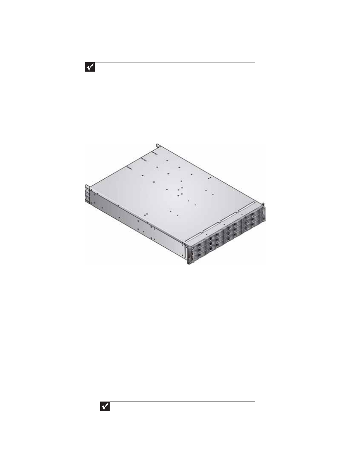
The Gateway E-842R SAS Enclosure Platform is a 2U (rack space) disk drive enclosure, housing
twelve low profile (1-inch high), 3.5-inch form factor hard drives, which can be either:
• 3 GB direct dock SAS disk drives,
• 3 GB direct dock SATA disk drives, or
• 3 GB dual path SATA disk drives through an active/active SATA mux transition card.
The system provides as much as 6TB of data storage per enclosure when 500 GB drives are
installed.
Expansion enclo sure
RAID enclosure expansion is achiev ed b y connecting expansion enclo sures. Multiple enclosur es are
connected together using SAS pat ch cables. You can connect as many as five enclosures. For more
information, see “Enclosure cabling - multiple enclosures” on page 25.
The enc losure
The Gateway E-842R design concept is based on an enclosure subsystem together with a set of
plug-in modules. The enclosure platform, as equipped, includes:
• Chassis and backplane with integrated (front panel mounted) operator’s panel.
• As many as 12 drive carrier modules, containing either:
• 3 GB direct dock SAS disk drives,
• 3 GB direct dock SATA disk drives, or
• 3 GB dual path SATA disk drives through an active/passive SATA mux transition card.
airflow. See “Dummy carrier modules” on page13.
2
Important
Dummy carrier modules must be fitted in all unused drive bays to maintain
Page 9
• Two plug-in power supply modules, 100-240 V AC, 350 W.
• One plug-in cooling fan module.
• Two plug-in controller modules, each incorporating a RAID controller and a StorView
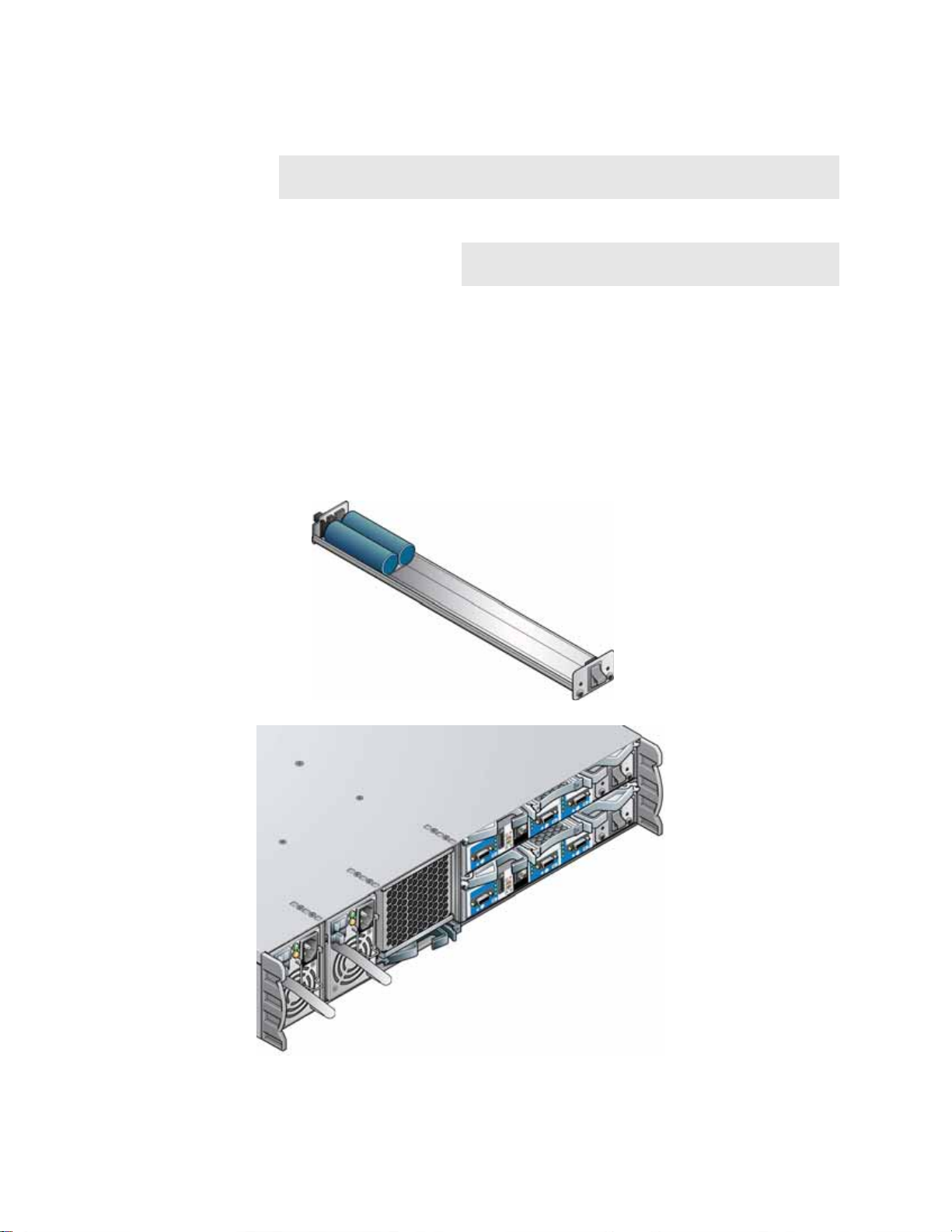
Enclosur e chas sis
The chassis consists of a sheet metal enclosure assembly containing a backplane printed circuit
board (PCB) and m odule runner system.
• The chassis front panel incorporates an integrated operator’s (Ops) panel.
• The backplane PCB provides logic level signal and low voltage power distribution paths.
• The chassis has 19-inch rack mounting features so it fits into a standard 19-inch rack and
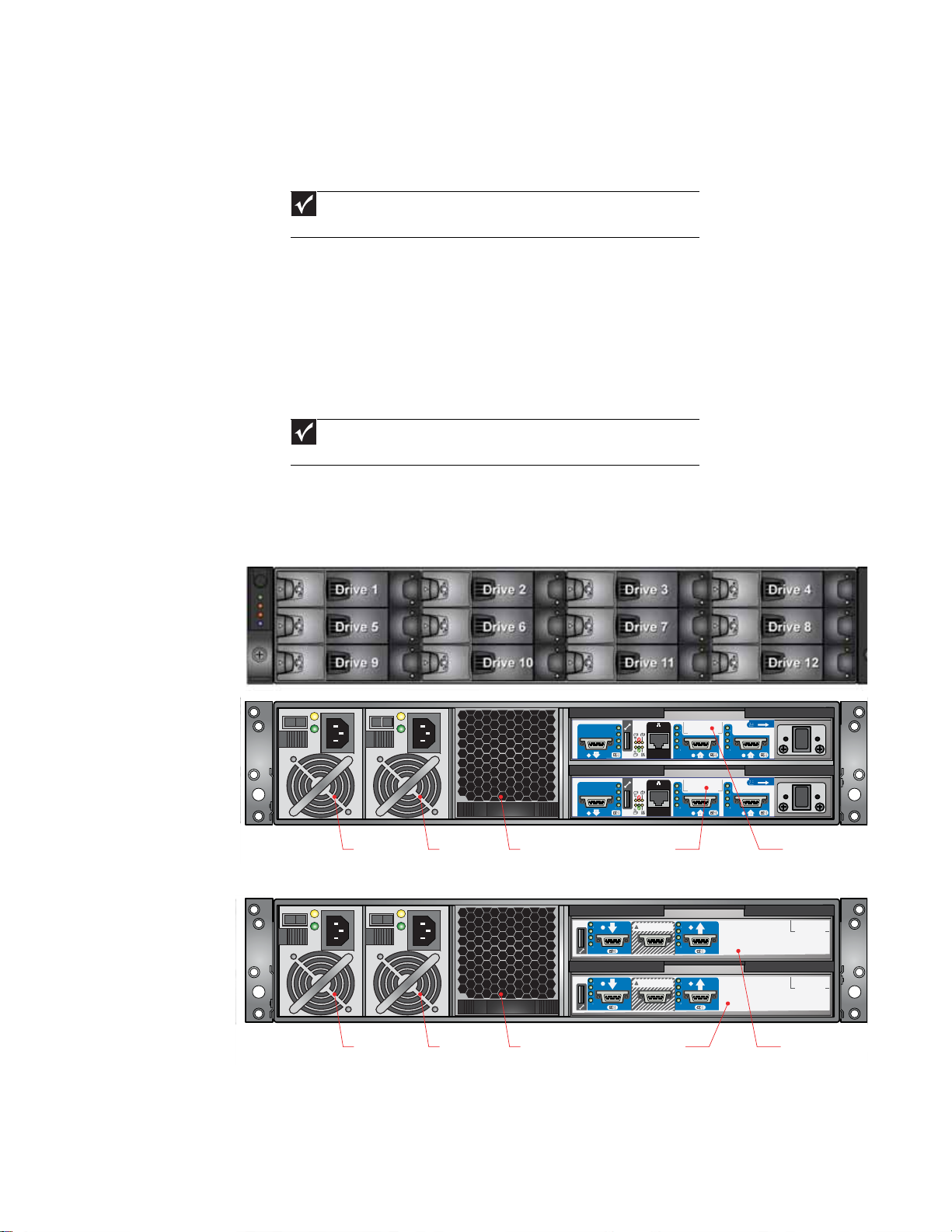
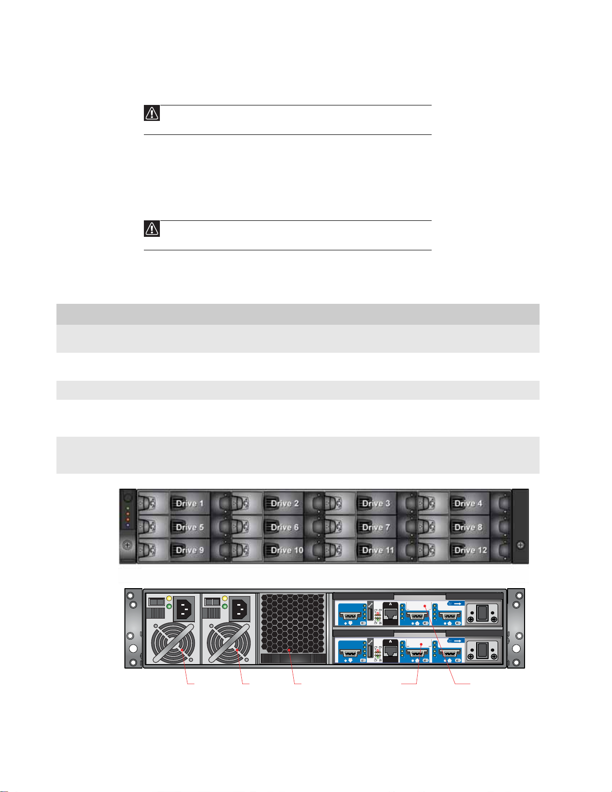
The chassis assembly contains 12 drive bays at the front, each of which accommodates the
appropriate plug-in drive carrier module. The 12 drive bays are arranged in 3 rows of 4 drives per
row . In t he back , the ch assi s ass embly contain s fiv e plug-i n module ba ys t o hou se tw o powe r supply
modules (PSUs), a cooling fan module, and two c ontroller modules, whic h are installed hori z ontally
(one above the other) in the right bay.
www.gateway.com
Management Module.
Important
If only one controller module is installed, a blank module must be installed
in the unused slot.
uses 2 EIA units of rack space (3.5” high).
Important
A drive bay is defined as the space required to house a single 1.0" high, 3.5-
inch disk drive in its carrier module.
0
1
0
1
PSU 1 PSU 2 Cooling Module
RAID en closure (ba ck)
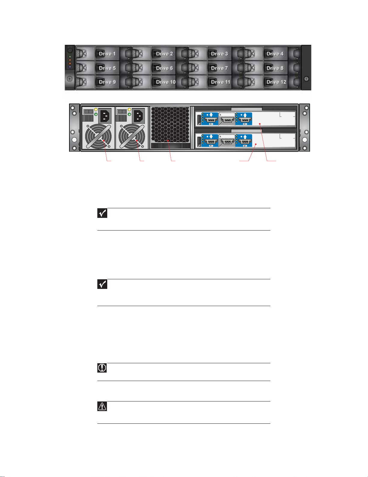
PSU 1 PSU 2 Cooling Module Disk I/O Module 1Disk I/O Module 0
Expansion enclosure (back)
RAID Controller 0
FACTORYUSE ONLY
FACTORYUSE ONLY
RAID Controller 1
3
Page 10
Operator’s panel
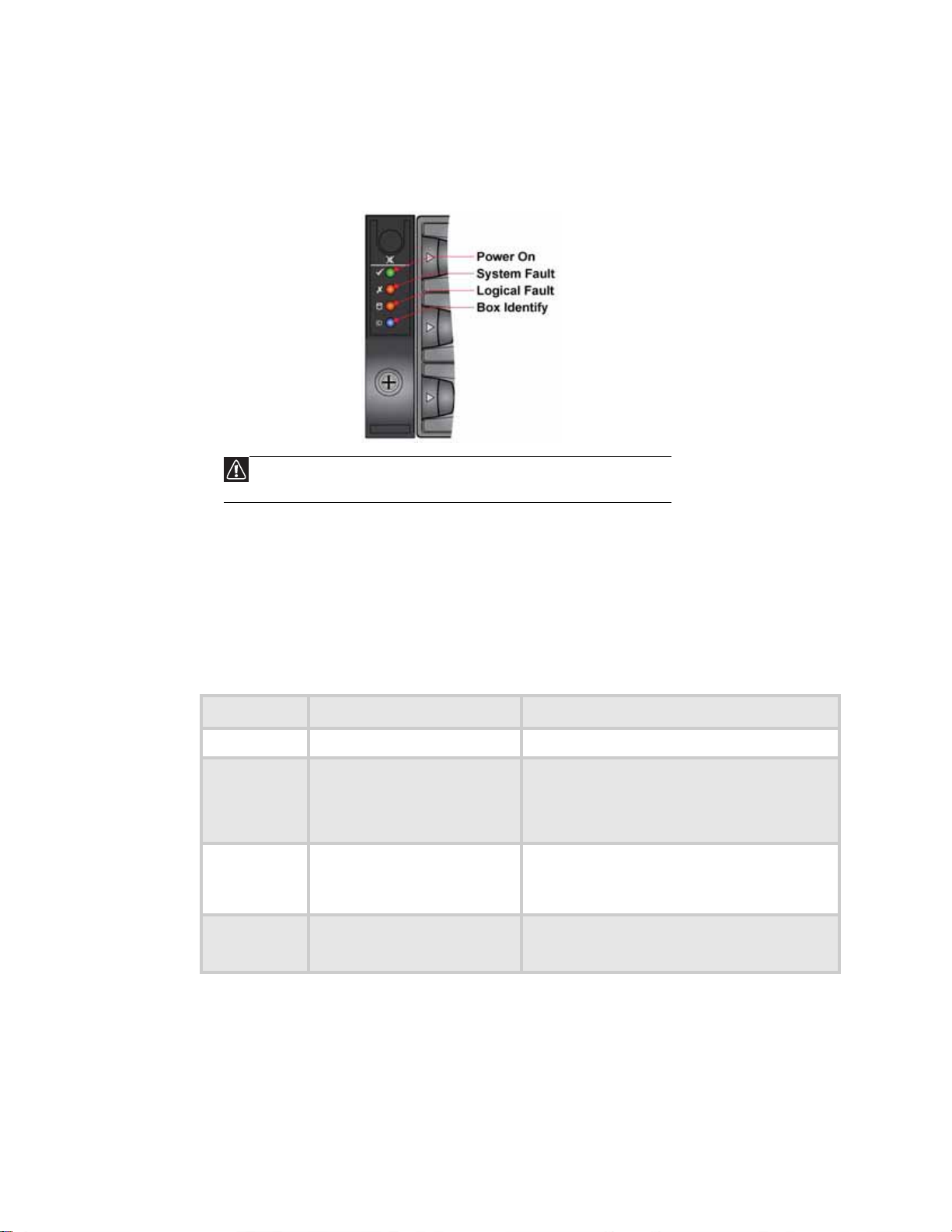
The enclosure’ s f ront panel has an integrated operat or’ s (Ops) panel w ith four LEDs. The Ops panel
provides you with a high level indication of the operation of the enclosure. See “Ops panel LEDs”
on page 8 for details of the LED status conditions.
separately. To replace the Ops panel, you must replace the entire enclosure.
CHAPTER 1: Introduction
Caution
The Ops panel is an integral part of the enclosure assembly and cannot be replaced
Alarms
Enclosure replacement should only be performed by trained personnel.
Visible alarms
The functional modules have associated status LEDs. The Ops panel shows a consolidated status
for all modules. LEDs show constant green or blue to indicate good or positive status. Constant
or flashing orange LEDs indicate the presence of a fault within that module.
LED State Description
Power On Co nstant green Good or posit ive status
System Fa ult Constant orange: fault present Indicates a problem with a power supply, cooling, or
controller module. For more information, see the
tables in “Power supply module LEDs” on page 13,
“Cooling Module LED” on page13, and “Controller
module LEDs” on page15.
Logical Fault C onstant orange: fault present Indicates f ailure of a dr iv e module. Th e failing module
is indicated by the Fault LED. For more information,
see the table in “Drive carrier m odul e faults” o n
page 16.
Box Identity Constant bl ue: en closure ident ity You can light this LED through the management
interfaces to indicate which enclosure requires
servi ce act ion s.
4
See “Ops panel LEDs” on page8 for a description of the Ops panel LED states.
Page 11
Audible alarms
The Gateway E-842R enclosure includes an audible alarm which indicates when a fault state is
present. The following conditions activate the audible alarm:
• Fan fau lt
• Voltage out of range
• Over temperature
• Thermal overrun
• Syste m fau l t
• Logi ca l Fa ul t
• Power supply module fault
When the audible alarm sounds, you can mute it b y pressing the Alarm Mute button on the front
panel. For more information, see “Audible alarm mute” on page 16.
The plug-in module s
A Gateway E-842R enclosure requires the following modules for normal operation:
• Two 350 W AC power supply modules.
• One cooling module.
• One or two controller modules.
• As many as 12 drive carrier modules.
• Dummy drive carrier modules, as required.
www.gateway.com
Important
No drive bays should be left comple tely empty. Dummy carriers or bl ank modul es
must be installed in all unused bays.
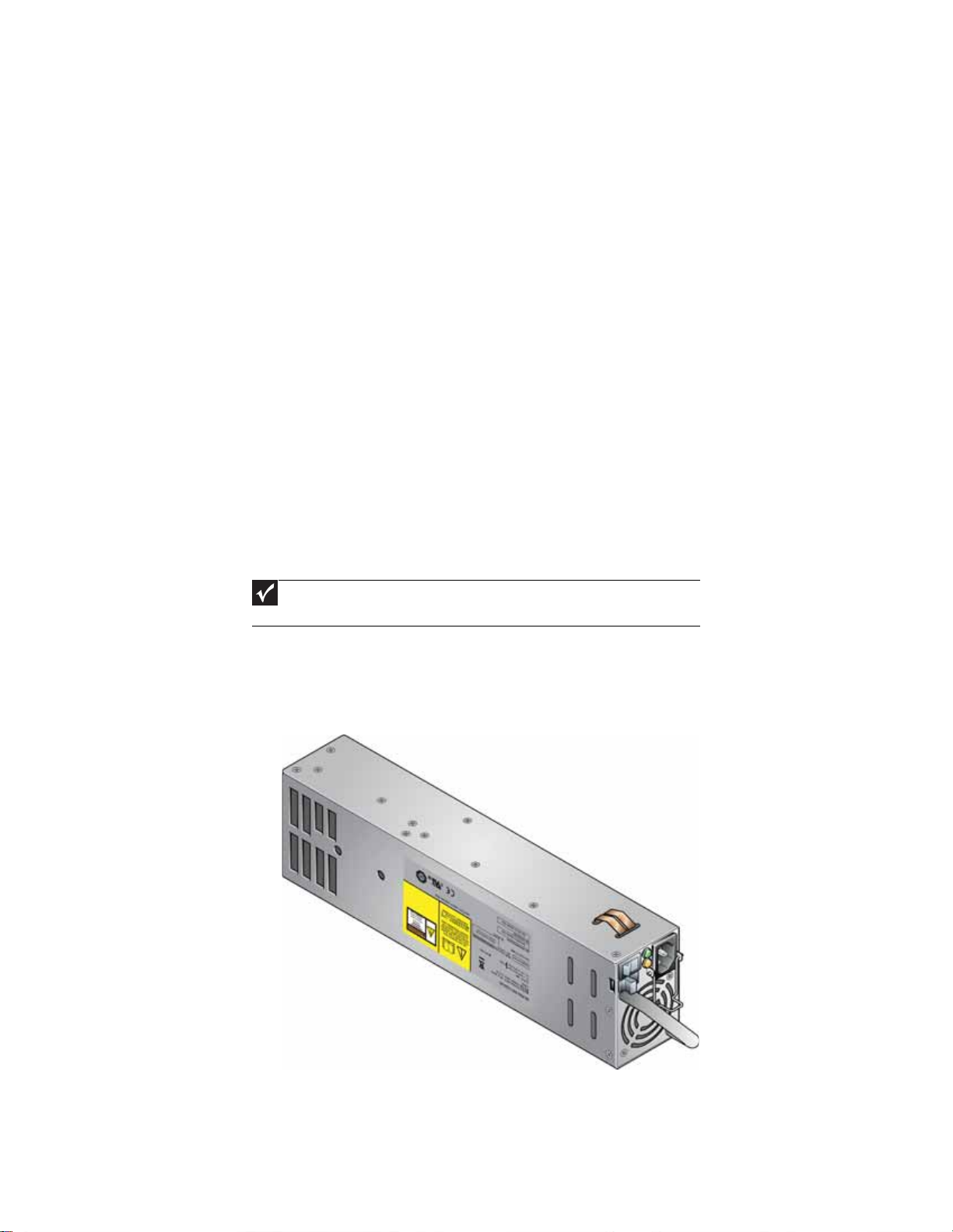
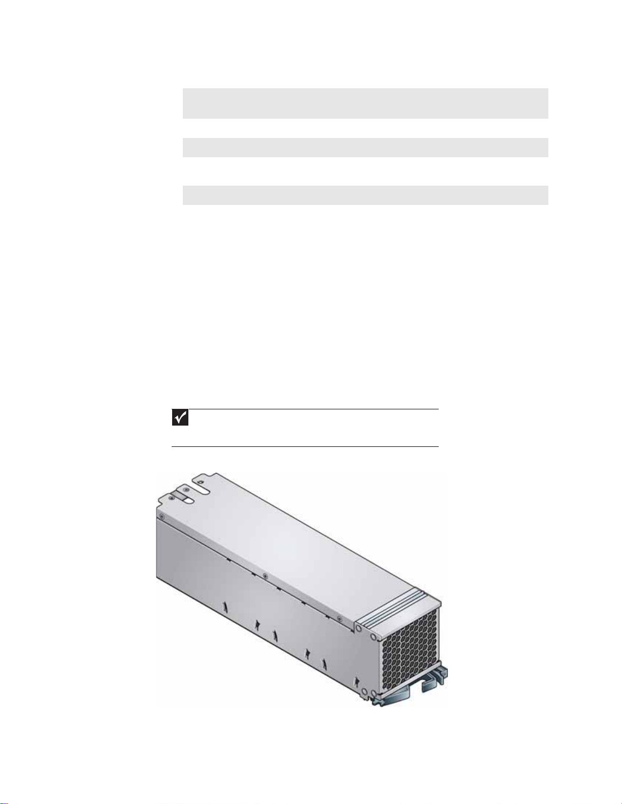
AC po wer suppl y module
Two, 100V-260 VAC 350 W power supply modules are supplied and mounted in the back of the
enclosure as part of the enclosure’s core product.
Power supply module input voltage operating ranges are nominally 115V or 230V AC, selected
automatically.
5
Page 12
CHAPTER 1: Introduction
T wo LEDs mount ed on the r ear panel of the pow er supply module indicate the status of th e module:
Multiple power supply modules
In order to maintain the appropriate airflow, you must always operate the Gateway E-842R with
two power supply modules installed. The two power supply modules operate together so if one
fails, the other maintains the power supply and cooling while you replace the faulty module.
Module replacement should only take a few minutes to perform but must be completed within
10 minutes from removal of the failed module.
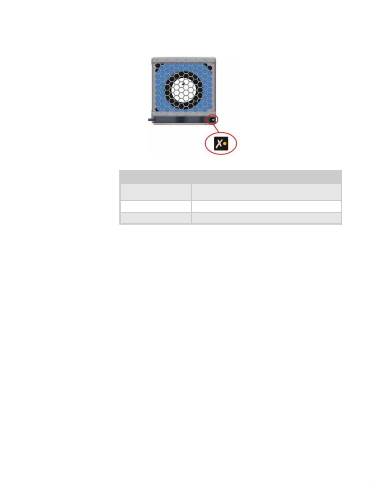
Cooling module
The cooling module provides system cooling, thermal monitoring, and control functions.
System airflow is from the front to the back of the enclosure:
Power On & OK
(Green)
Off Off No AC power (either power supply module)
Off On No AC power (this power supply module only)
On Off AC present, power supply module on and OK
On On Power supply module fan fault
Module Fault
(Orange)
Status
Power supply module fault (over temperature, over
voltage, over cur r e nt, or power supply module fan fail)
• Cooling air passes over drives and through the midplane to a central air passage.
• The cooling module pulls air from the air passage and from the controller modules.
Important
The system must be operated with a low pressure rear exhaust installation
(back pressure created by rack doors and obstacles not to exceed 5 pascals (0.5mm
water g au ge) ) .
• The power supply modules pull cooling air fr om t he air pass age at the back of the enc lo sure .
6
Page 13
www.gateway.com
The module has an orange Cooling Module Fault LED.
LED status is described in the following table:
Module Fault (Orange) Status
Off Enclosure Off - Indic ate d by pow er supp ly module and contr oller
Off Enclosure On - Fan OK
On Cooling module fan failure
module OK lights
7
Page 14
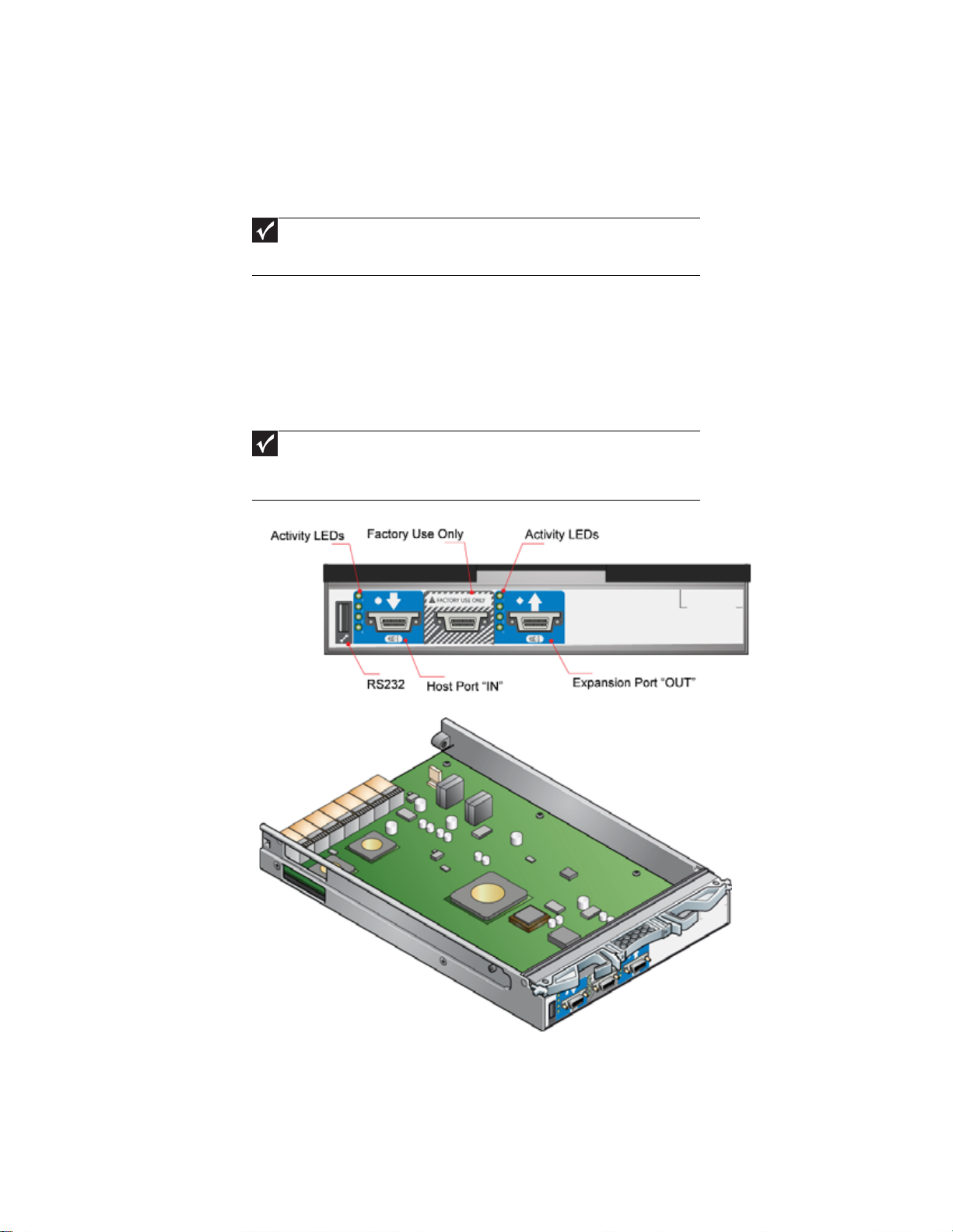
Contr oller module
CHAPTER 1: Introduction
Caution
Operation of the enclosure with any modules missing disrupts the airflow and the
drives do not receive sufficient cooling. All openings must be filled before operating the
enclosure.
When only one controller module is installed, a blank m odule mu st b e ins talled in the vacant
controller module slot at the rear of the enclosure to maintain airflow and ensure correct
operation.
Important
Do not mix Disk I/O modules and RAID Controller modules in the same enclosure. Disk
I/O modules are only installed in the expansion enclosure and RAID Controllers are only
installed in the RAID enclosure.
One or two controller modules (depending on your configuration) are supplied and mounted in
the back of the enclosure as part of the Gateway E-842R enclosure core product.
The plug-in controller modules have been designed for integration into the enclosure, providing
external FC cable interfacing with the host computer system.
The backplane incorporates a connection to each of the SAS ports within the controller modules.
The controller module’s internal processor monitors error conditions on each disk drive port.
Processors housed on the controller modules prov ide enclosure management interfac ing to devices
on the backplane, power supply module, controller module, and Ops panel to monitor internal
functions. These processors operate in a dual active configuration to allow failover.
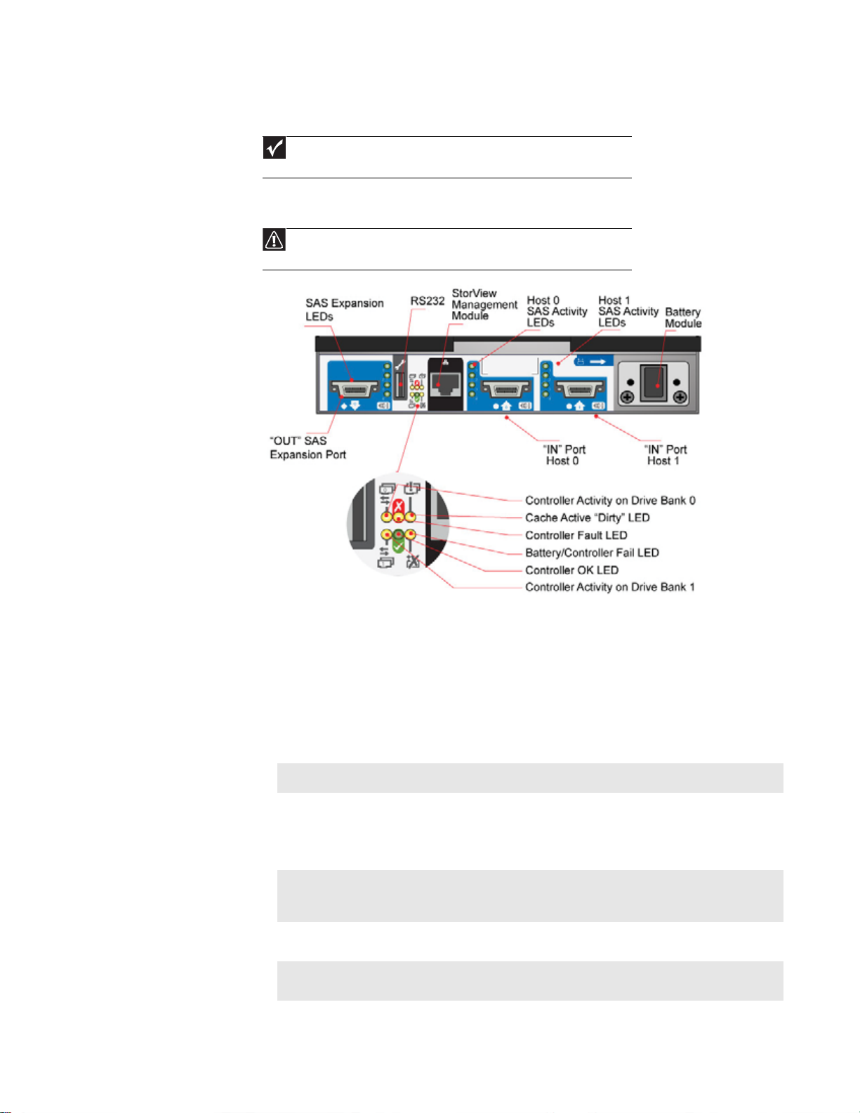
The module incorporates LED indicators. For the location of the LED indicators, see “Controller
module LEDs” on page 8.
External ports
The RAID controller module has the following external ports:
• Two external (host) SAS ports that allow for fitting of Small Form-Factor Pluggable (SFP)
modules, with auto-bypass at the output. Either or both of these SFP ports can be used to
provide connection to the host controllers. Each host port operates at 3 Gb/s, giving an
effective speed of 6 Gb/s. These ports are also backwards compatible with 2 Gb/s hosts.
• An SAS expansion port suppor ts a s man y as four expansion enclosur es t hr ough an SFF-8470
connector.
8
Page 15
www.gateway.com
• An RJ45 10/100BaseT Ethernet port lets you connect the controller to a network to enable
out-of-band management and monitoring using the embedded StorView GUI software.
Important
Only shielded, Cat 5 (or better) cables should be used for connection to the
Ehternet port for EMC performance.
• There is also an RS232 socket which provides an alternative user interface to the RJ45
connector.
Caution
Although the RS232 port is similar in appearance to a USB port, it requires a
special cable and you should not attach a USB cable to it.
The recommended configurations are shown in “Ethernet connection” on page 24 and “Enclosure
cabling - multiple enclosures” on page25.
StorView Management software
The StorView Storage Management software which is embedded in the controller module is a
full-featured, graphical, HTML-based software suite designed to configure, manage, and monitor
the controller module storage solution. T he module is configured w i th a base IP address t o l et you
connect to it. See “StorView Storage Management software” on page29 or the Gateway E -842R
StorVi ew Sto rag e Ma nag emen t Soft wa re User Gui de for further information.
LED functions LED state Definition
Battery fault Orange When lit, this LED indicates that the backup
Cache active Orange When lit, this LED indicates that the RAID
Controller a ctivity on drive
bank 0
Controller a ctivity on drive
bank 1
Orange When lit, this LED indicate s ac ti vity on the Bank
Orange When lit, this LED indicate s ac ti v i ty on the Bank
battery unit is missing, has low voltage, has
experienced a time-out on charge indicating a
faulty bat t ery, or has exper ience d a fa u lt in the
chargin g circuitr y.
controller cac he has data s a ved in me mory but
not written to the disk array.
0 disk drives.
1 disk drives.
9
Page 16
CHAPTER 1: Introduction
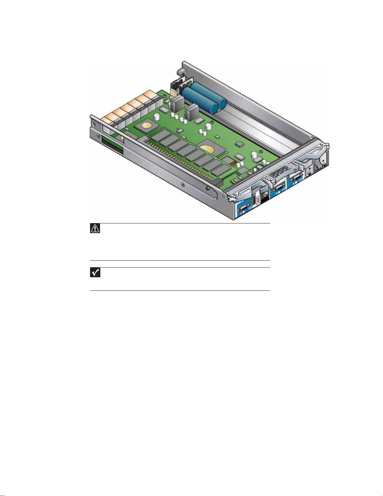
Batt ery module
Each controller module assembly includes a removable battery module (for the location, see
“Controller module” on page8). The battery module contains a replaceable Li-Ion battery pack,
as shown i n the f ol low ing illu str ation. T he bat t ery pack pr ot ec ts the cach e cont ents if th e A C pow er
fails. You can check the amount of battery time available through the Management Interface. The
amount of time available is dependent on the amount of cache in the system.
See “Battery mo dule” on pag e 24 for removal and replacement procedures.
Controller OK Green When lit, this LED indic at e s tha t RAID contr oller
activity is normal.
Controller fault Orange When lit, this LED indicates that a RAID
controller fault has occurred.
Ethernet status Green When lit, this LED indicates that the Ethernet
port has a valid connection.
Orange When lit, this LED indicates that the Ethernet
port has activity.
SAS activity Green When lit, these LEDs show I/O activity on the
specific port lane indicated.
10
Page 17
Disk I/O module
The expansion enclosure houses one or two Disk I/O modules. They provide the drive expansion
for the RAID enclosure . When expanding the sy stem, y ou may add up to f our expansion enclos ures.
This will give you a total of five enclosures including the RAID enclosure. A fully loaded system
will provide a total of 60 disk drives.
I/O modules are only installed in the expansion enclosure and RAID Controllers are only
installed in the RAID enclosure.
Processors housed on the Disk I/O modules provide enclosure management and an interface to
the devices on the backplane, PSU, Disk I/O module and Ops panel, which monitor internal
functions. These Disk I/O module processors operate in a master-slave configuration to allow for
failover.
The enclosure may be configured with either one or two modules. If only one Disk I/O module is
installed, a blank module must be installed in the unused bay.
Each SAS connector has four LEDs adjacen t to the connector. The LEDs indica te I/O activity on that
specific SAS port lane where each port has four lanes.
the Disk I/O module in the next E-842R enclosure in a multiple enclosure configuration, See
“Enclosure cabling - multiple enclosures” on page 25 for further information on enclosure
expansion.
www.gateway.com
Important
Do not mix Disk I/O modules and RAID Controller modules in the same enclosure. Disk
Important
The OUT port on the RAID Controller or DIsk I/O module connects to the IN port on
11
Page 18
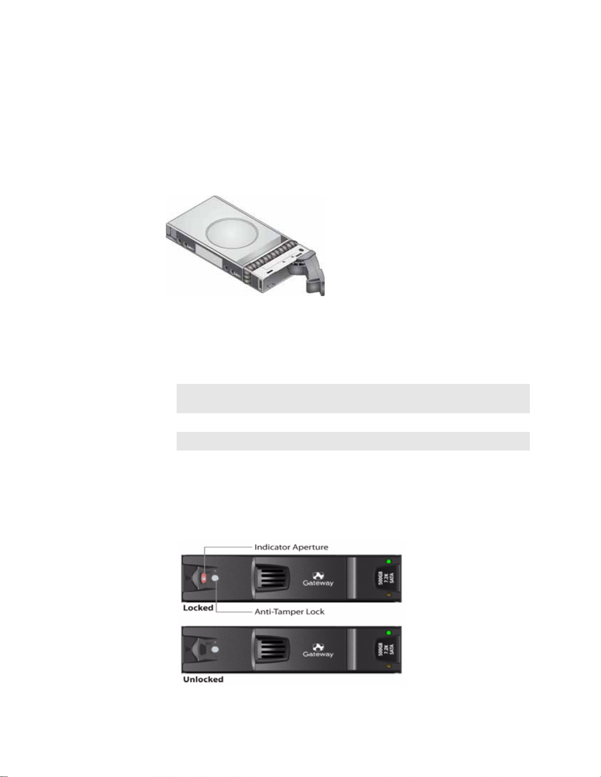
Driv e carr ier module
The drive carri er module comprises a hard disk mounted in a carrier . Each dri ve bay hou ses a single,
low profile, 1.0-inch high, 3.5-inch form-factor disk drive in its carrier. The carrier has mounting
locations for SAS or SATA drives.
The front cap also supports an ergonomic handle which provides the following functions:
• Inserting the carri ers i nto the drive b ays
• Removing the carriers from drive bays
• Positive “spring loading” of the drive/backplane connector
• An anti- tamper lock op erated by a torx-socket type key
CHAPTER 1: Introduction
Drive status indicat ors
Each drive carrier has two LEDs, an upper (green) and lower (orange). In n ormal operation the
green indicator is ON and flickers as the drive operates. The orange indicator is only ON i f there
is a drive fault. If the green LED is OFF when the orange LED is ON, a power control circuit failure
is indicated.
Power On & OK
(Green)
On Off Normal o peration
On On Drive fault
Off On A power co ntrol circuit failure
Module Fault
(Orange)
Status
Anti-tamper locks
Anti-tamper locks are installed in the drive carrier handles and are accessed through the small
cutout in the latch section of the handle. These locks are provided to disable the normal “pinch”
latch action of the carrier handle.
12
Page 19
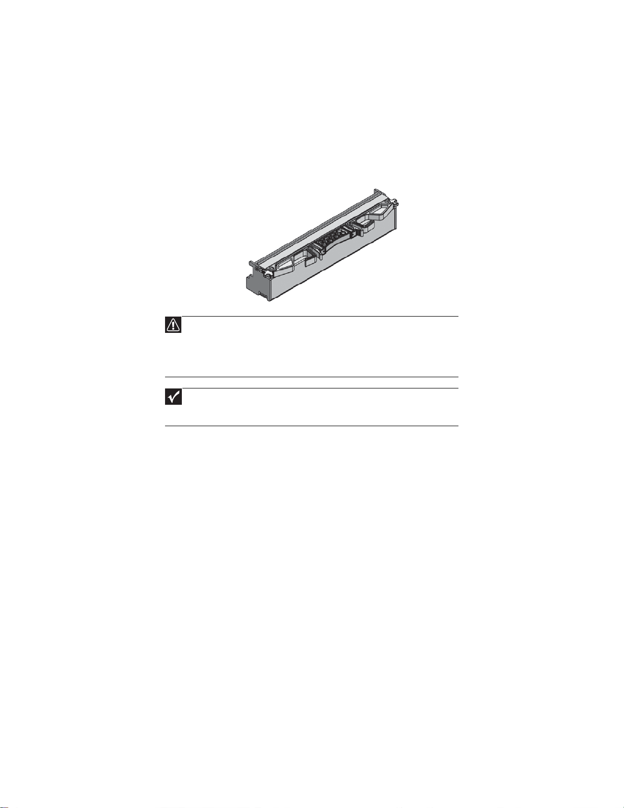
Dummy ca rrier mo dules
Dummy carrier modules are provided for fitting in all unused drive bays. They are designed as
integral drive module front caps and must be installed in all unused drive bays to maintain a
balanced airflow.
Blank modules
Caution
Operation of the enclosure with any modules missing disrupts the airflow and the
drives do not receive sufficient cooling. All openings must be filled before operating the
enclosure.
When only one controller module is installed, a blank m odule mu st b e ins talled in the vacant
controller module slot at the rear of the enclosure to maintain airflow and ensure correct
operation.
www.gateway.com
Important
Do not mix Disk I/O modules and RAID Controller modules in the same enclosure. Disk
I/O modules are only installed in the expansion enclosure and RAID Controllers are only
installed in the RAID enclosure.
13
Page 20

CHAPTER 1: Introduction
14
Page 21

CHAPTER 2
Getting Start ed
• Introduction
• Planning your inst allation
• Enclosure installation pr ocedures
• Module installation
• Enclosure conf iguration
• Enclosure cabling - single enc losur e
• Ethernet connec tion
• Enclosure cabling - multiple enclo sure s
• Driv e slot ar rangeme nt
• Po wer cord conne ction
• Grounding checks
• Management int er fa ces
15
Page 22
CHAPTER 2: G etting Sta rted
Introduction
Caution
When connecting the enclosure, use only the power cords supplied or cords which
match the specification quoted in “Specifications” on page29.
This chapter e xplains ho w to install your enclosure int o a n industry-standard, 19-inch rack cabinet
and configure the enclosure sub-system.
Planning y our installation
Caution
Blank modules or dummy carrier modules MUST be installed in ALL unused bays or
the enclosure may overheat.
Befor e you begin installation, yo u should become familiar with the con f iguration requirements of
your enclosure , detailed in the f ollow ing table. The corr ect posi tions of each of the optional plug-in
modules are shown in the illustration. See “Ethe rnet connec tion ” on p age24 and “Enclosure cabling
- multiple enclosures” on page 25 for details of controller module configurations.
Module Location
Drive bays All drive bay s mu st hav e a driv e carr ier module or dumm y dri ve carr ier module instal led. No bay s should
Power supply (PSU)
modules
Cooling module Install the cooling module in the rear bay, as shown in the following illustration.
Controller module Two RAID controller modules (or one controller module and one blank module) can be installed,
Disk I/O module Two Disk I/O modules (or one Disk I/O module and one blank module) can be installed, depending on
be left empty.
T wo pow e r suppl y mod ule s mu st be installe d. F ull pow er r edun dancy is pr o v ided w hile a f ault y mo dule
is replaced. Install the power s upp ly modules in the left rear bays, as sho wn in the f oll owing illustrat io n.
depending on the configuration you require. The modules are installed horizontally (one above the
other) in the right rear bay.
the configuration you require. The modules are installed horizontally (one above the other) in the right
rear bay.
0
1
16
PSU 1 PSU 2 Cooling Module
Enclosure module
0
1
RAID Controller 0
RAID Controller 1
Page 23
www.gateway.com
PSU 1 PSU 2 Cooling Module Disk I/O Module 1Disk I/O Module 0
Disk I/O module
Enclo sure dr iv e bay numbering con v ention
FACTORYUSE ONLY
FACTORYUSE ONLY
Important
Drive carrier modules must always be installed in drive locations 1 and 12. This is the
minimum configuration required for the system to operate and provide SES Management
Services.
The enclosure driv e bay numbering conv ention is shown in the illustration on page16. A drive bay
is defined as the space required to house a single 1.0-inch high, 3.5-inch disk drive in its carrier
module.
Driv e carrier conf iguration
Important
Before you begin installation, you should become familiar with the configuration
requirements of your enclosure. There must be a drive present in drive locations 1 and 12
to enable SES communications to operate. Installing drives in both of these bays provides
redundant SES communication paths.
When planning your system configuration, remember that all enclosure drive bays must be filled
with either a drive carrier or dummy drive carrier module. No bays should be left empty.
Enclo sure installation procedur es
Warning
An enclosure with all component parts installed is too heavy for a single person to
safely install alone into a rack cabinet.
The following procedures describe the installation of an enclosure and highlight any critical
requirements and good handling practices you should follow to ensure a successful installation.
Caution
Make sure that you wear a suitable anti-static wrist or ankle strap and observe all
conven ti o nal ESD p recautions when han dl ing modules and compone nts. Avoid c on tact with
such things as backplane components and module connectors.
17
Page 24
CHAPTER 2: G etting Sta rted
Preparing the sit e and host s erver
Important
The E-842R system supports most of the widely used operating systems. However
deployment on M ic r osoft Windows requires t he .i nf dri v e r fil e whic h i s found on the Gat eway
External Storage CD (ESCD). (For Windows Servers, insert the ESCD and install the .inf file.)
Before you begin, make sure t hat the site where you intend to set up and us e your storage system
has the following:
• Standard AC power from an independent source or a rack power distribution unit with a
UPS (universal power supply).
• A host computer with a standard Fibre Channel HBA (host bus adapter) with the latest BIOS
and drive rs. Follo w the instr uction s pro vided wit h y our HBA and inst all the HBA an d its dri ver
software, if necessary.
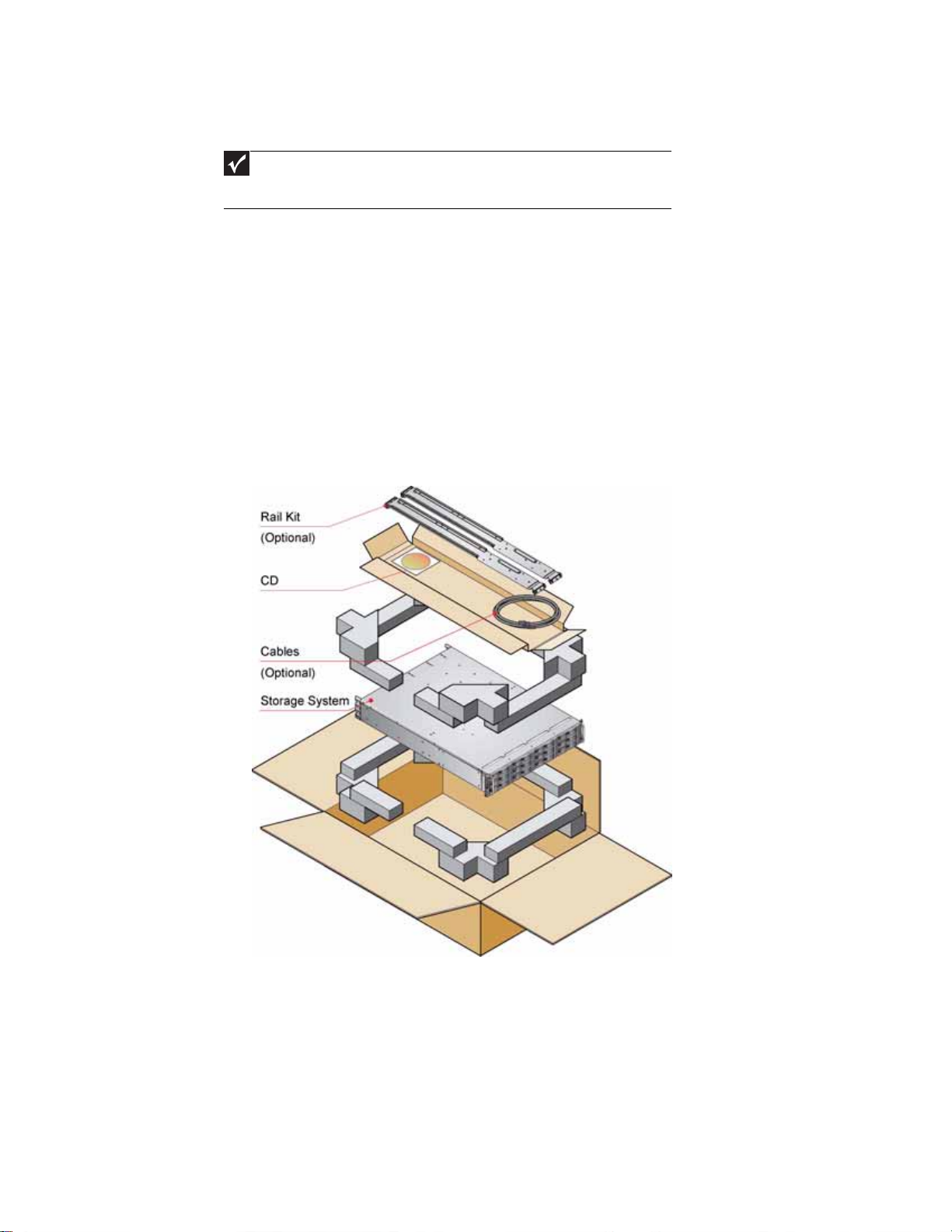
Unpacking t he enclosur e sy stem
The package contents and unpacking procedure are outlined in the following illustration.
The accessory box contains the AC power cord(s), a serial communication cord, and the software
and the Gateway External Storage CD (ESCD). The accessory box insert contains the adjustable rail
slides and hardware parts to rack mount the enclosure.
18
Page 25

Rac k installation prer equisit es
The enclosure is designed for installation into an industry standard, 19-inch cabinet, capable of
holding the unit.
• A minimum depth of 28 inches (700 mm) from the front flange to the back metalwork
(excludes back cabling).
• Up to 70.5 lbs (32 kg) per enclosure, depending on configuration.
• A minimum gap of 1 inch (25 mm) of clearance between the rack cover and the front of the
drawer, and 2 inches (50 mm) of rear clearance between the back of the drawer and the
back of the rack is recommended, in order to maintain the correct airflow around the
enclosure.
• The rack should have a maximum back pressure of 5 pascals (0.5 mm water gauge).
Rack mounting rail kit
A set of mounting rails is a vailable for us e in 19-inch rac k cabi ne ts. T he s e r ails have been designe d
and tested to handle the maximum enclosure weight and to ensure that multiple enclosures may
be installed without loss of space within the rack. Use of other mounting hardware may cause
some loss of rack space.
The rack mounting rail kit also incorporates a rear hold down mechanism to ensure shock and
vibration immunity.
Contact Gateway Customer Care to make sure that suitable mount rails are available for the rack
you are u si ng .
www.gateway.com
Rac k installation procedur e
See the detail drawings supplied with the rack mounting rail kit for additional information.
Installation procedure
To install the rack mounting rail kit:
1 Attach left and right chassis slides to the enclosure sides using 8 M3x4 button head screws.
19
Page 26

CHAPTER 2: G etting Sta rted
2 Assemble the left and right chassis latches using the special chassis latch screws. Make sure
that the la tc h is orientat ed as sh own in th e f ollo w ing illu stra tion, w it h the sp ring ar m locat ed
aga ins t i ts stop (o n the rig ht si de a t t he top, on the le ft s ide at the bo ttom ) .
3 Assem bl e th e ra ck brac kets to th e ra ck p osts as follo ws:
a Fit the location pin at the back of the rail into the rear rail post.
b Extend the rail to fit between the front and rear rack posts.
c Attach the rail to both the front and rear of the rack using the washers and screws
supplied. The screws should be left loose enough to allow for sideways movement of
the rail.
d Tighten the two clamping screws located on the inside of the rear section of the rack
bracket.
Guide pin
Rack bracket
Front rack post
Remove the nut when you use
tapped hole rack posts.
Rea r r ac k p os t
Clamping screws
Slide washer
Square hole rack
Guide pin
Phillips screw
Tapped hole rack
20
Page 27

www.gateway.com
4 Mount the enclosure in the rack as follows:
a Lift the enclosure and align it with the rack rails.
b Carefully insert the chassis slides into the rack rails and push it fully into the cabinet.
c Tighten the re ar screws.
d Withdraw the enclosure until it reaches the hard stops (approximately 15.75 inches
(400 mm)).
e Return the enclosure to the fully installed position and attach to the rack using the
captive thumbscrews on th e front fla nges.
Module installation
The enclosure comes fully populated w ith all plug-in modules i nstalled. For inf ormation on remo val
or replacement of plug-in modules, see “Troubleshooting” on page 11.
Enclo sure configuration
Enclosures are configured with one internal domain of 12 drives per controller module.
Enclo sure cabling - single enclo sure
The RAID controller module provides bi-directional connection between the ho st-side interf ace and
the drives. The drives will not be presented to the Host until they are configured and mapped by
the controller.
21
Page 28

CHAPTER 2: G etting Sta rted
Each E-842R RAID controller module can be connected t o up to tw o independent Host Bus Adaptors.
Some typical configurations utilizing one or two RAID controller modules and either one or two
HBAs are shown in the following.
Single host, single HBA, and single controller connection
22
Dual host, single HBA, and single controller connections
Single host, dual HBAs, and dual controller connections
Page 29

www.gateway.com
Dual hosts, dual HBAs, and dual controller connections
Dual host, single HBA, and dual controller connections
Etherne t connection
Important
Only shielded Cat 5 (or better) cables should be used for connection to the Ethernet
port for EMC conformance.
An RJ-45 10/100BaseT Ethernet port lets you connect the controller to a network to enable out-of
-band management and monitoring using the Embedded StorView GUI software.
Make sure that the PC is connected either directly or through a switched LAN to the Ethernet.
23
Page 30

CHAPTER 2: G etting Sta rted
Enclo sure cabling - multiple enclo sures
Y ou can connect additional expansion enclosure s to an E-84 2R RAID enclosure . Multiple enclosures
are connected t o gether using SAS patch cables, up to a maximum of five enclosures, including the
RAID enclosure. A typical two-expansion enclosure configurati on is shown below . T o fully populate
your installation t o the maximum number of enclo sure s, f ollo w th e ex ample belo w connecti ng the
enclosures in the same fashion for each additional expansion enclosure.
Dri ve slot arr angement
Each enclosure has 12 drives which are referenced by their locations as shown in the following
table. Drives are numbered column/row. For information on installing drive carrier modules, see
“Installing a drive carrier module” on page27.
Column/row 1 2 3 4
1 Drive 1 Drive 2 Drive 3 Drive 4
2 Drive 5 Drive 6 Drive 7 Drive 8
3 Drive 9 Drive 10 Drive 11 Drive 12
24
Page 31

Driv e location rules
The E-842R storage enclosure supports two different types of disk drives, SAS and SATA. In order
to allow optimal configurations to be built, the following rules should be observed:
Different drive types cannot be mixed in the same column.
• Slots 1, 5, 9 = colu mn 1
• Slots 2, 6, 10 = column 2
• Slots 3, 7, 11 = column 3
• Slots 4, 8, 12 = colum n 4
To achieve optimum performance, drives should be populated in the following sequence:
• Initially—Sl ots 2, 6, an d 10
• Then —Sl ots 3, 7, and 11
• Then —Sl ots 1, 5, an d 9
• Then—Slots 4, 8, an d 12
Drive Location Sequence (1)
Column/row 1/# 2/# 3/# 4/#
#/1 - 2 - #/2 - 6 - -
www.gateway.com
#/3 - 10 - -
Drive Location Sequence (2)
Column/row 1/# 2/# 3/# 4/#
#/1 - 2 3 #/2 - 6 7 #/3 - 10 11 -
Drive Location Sequence (3)
Column/row 1/# 2/# 3/# 4/#
#/1 1 2 3 #/2 5 6 7 #/3 9 10 11 -
Drive Location Sequence (4 )
Column/row 1/# 2/# 3/# 4/#
#/1 1 2 3 4
#/2 5 6 7 8
#/3 9 10 11 12
25
Page 32

CHAPTER 2: G etting Sta rted
If you need to change drive technology, a new column of drives should be populated.
Column/row 1/# 2/# 3/# 4/#
#/1 - SAS 2 SATA 3 #/2 - SAS 6 SATA 7 #/3 - - SATA 11 -
All members of the column should have the same drive type.
Drive start
With two active power supply modules installed (required), all drives start immediately.
Activa ting the anti-tamper locks
The anti-tamper locks are installed in the drive carrier handles and are accessed through the small
cutout in the latch section of the handle.
Drives are supplied with the locks set in the locked position.
Important
You cannot install a drive carrier if its anti-tamper lock is activated before installing
it into the enclosure.
To a c t iv a te t he l o c k s:
1 Carefully insert the provided lock key into the cutout in the handle.
2 Rotate the key clockwise until the indicator is visible in the opening b eside the key.
3 Remov e th e key.
4 To deac ti vat e t he lock, r otate the k e y counte r -cloc kw ise until th e indicat or is no longer vis ible
in the opening beside the key.
26
Page 33

www.gateway.com
P ower cor d connection
Caution
Before turning on the enclosure, carry out the grounding checks detailed in
“Grounding checks” on page28.
To attach the power cord:
1 Attach the power cords to the power supply modules. The cable strain relief bale fits over
and onto the power cord. Lift the bale up first, insert the cable, and secure the bale onto
the power cord .
Caution
The power connections must always be disconnected prior to removal of the
power supply module from the enclosure.
2 Attach the power cord to the power distribution unit in the rack or other power source.
3 A Power On LED on the Ops panel indicates whether AC power is present.
Grounding c hecks
Perform these checks to make sure that a safe grounding system is provided.
• If a rack distribution system is being used.
• Make sure that power is removed from the rack.
• Connect the power cord to the rack distribution system and the enclosure.
• If a direct connection is made with the power cord, make sure that it is connected to the
enclosure.
Caution
Some electrical circuits could be damaged if external signal cables or power
control cables are present during the grounding checks.
• Check for continuity between the earth pin on the IEC 320 connector on one of the power
supply modules and any exposed metal surface of the enclosure.
27
Page 34

CHAPTER 2: G etting Sta rted
Management int erface s
The following management interfaces are used to configure, manage, and monitor the controller
module storage solution.
StorV iew St orage Management s oftw are
StorView Storage Managemen t software is a full-featured, graphical, HTM L-based, software suite
designed to configure, manage, and monitor the controller module storage solution.
StorView provides a centralized local and remote management tool to control primary storage
assets v ital t o ensur ing maximum data r elia bility, network up-ti me , and sy s t em s ervic eability. This
tool also lets you manage and monitor the storage system from a host running StorView locally
and from a Web browser across the intranet or Internet.
StorView includes the StorView Server which runs as a background service and is responsible for
managing the installed modules.
The St orVie w Serv er dis cov ers s y st em st ora ge de v ices, man ages and distr ibute s me ssa ge log s, and
communicates with other StorView Servers installed on the same local and external subnet
networks.
A GUI provides the interface in an HTML-based front end which is accessed using a Web browser.
The software incorporates a Web server, Apache 2.0, that provides the interface between the
StorView Server and GUI. During installation, the Web server is automatically configured.
For m ore in form ati on , se e th e Ga teway E-842R StorView Storage Management Application User
Guide.
VDS
RAID contr oller config uratio n utility
The controller module firmware-based programs are accessed through a VT-100 terminal or
emulation.
Introduction
VDS (Virtual Disk Service) is a feature of Microsoft Windows Server 2003. It provides a consistent
interface for managing storage devices and creating volumes.
The Gateway Hardware Provider for VDS enables Virtual Disk Service to be used with the E-842R
RAID controller.
Sy stem requirements
Use of the Gateway Hardware Provider for VDS requires the following:
Hardware:
• An enclosure with an E-842R controller.
Operating System:
• Windows Server 2003 R2 only.
Software:
• A VDS client (optional)
• The Micros oft utility programs Stor age Manager for SANs (optional) and DiskRAID (optional).
28
Page 35

www.gateway.com
Installation
If the VDS service is running, it is stopped automatically while the provider is installed.
Important
The Gate way Hardw are Provid er for VDS can be instal led on a sy stem that alre ad y ha s
VDS providers from other vendors. Likewise, other VDS providers can be installed after
Gateway’s without any conflict.
To install the hardware provider for VDS:
1 Double-click the installer executable.
2 Read the lic ense a greemen t, the n click I Agree to a cc ep t to t he term s a nd co ndi ti ons .
3 Choose a destination folder for the application (or accept the default), then click Install.
4 When you are prompted that the installation is finished, click Close to close the installation
window.
Starting the VDS serv ice
The VDS service starts automatically when a client attempts to access it. However, under some
circumstances, you may need to manually start the VDS service.
To start the VDS service:
1 Click Start, Control Panel, Administrative Tools, then click Services.
2 Select Virtual Disk Services from the list, then click Start.
Using VDS
VDS is a Microsoft standard method for managing storage devices. Therefore, you should refer to
the o ffici al Micr osoft docu me nta ti on at:
http://www.microsoft.com/windowsserversystem/storage/storservices.mspx
The VDS Technical Reference is also available from Microsoft at:
http://technet2.microsoft.com/WindowsServer/en/Library/1dbc6c24-1477-4f73
-a0ae-57b4e90808d81033.mspx
Additional documentation is available from the SDK.
Two helpful tools exist for making use of VDS:
• DiskRAID i s a test too l th at ca n be use d to in terfa ce with VDS . I t i s in clu de d wi th t he VDS
SDK and can also be downloaded from Microsoft or found in the Resource Kit Tools.
• Storage Manager for SA Ns is a program for managing storage area networks that comes as
part of Windows Server 2003.
To install Storage Manager for SANs:
1 In the Windows Control Panel, click Add or Remove Programs, then click Add/Remove
Window s Com pon ents .
2 Select Management and Monitoring Tools from the list, then click Details.
3 Click the Storage Manager for SANs box, then click OK. Follow the on-screen instructions.
Supported VDS functions
The following VDS functions are supported by the Gateway Hardware Provider for VDS:
Object Method name
IEnumVdsObject Clone
Next
Reset
Skip
29
Page 36

CHAPTER 2: G etting Sta rted
Object Method name
IVdsAsync QueryStatus
IVdsController GetPortPropertie s
IVdsControllerControllerPort QueryControllerPorts
IVdsControllerPort Initialize (inte rnal)
IVdsDrive GetProperties
IVdsHwProvider QuerySubSystems
IVdsHwProviderPriv ate QueryIfCreatedLun
IvdsHwProviderType GetPr oviderType
Wait
GetProperties
GetSubSystem
Reset
SetStatus
QueryAssociatedLuns
Initialize (i nternal)
GetController
GetProperties
GetSubsystem
ClearFlags
SetFlags
SetStatus
Initialize (i nternal)
Reenumerate
Refresh
IVdsLun GetProperties
IVdsLunControllerPorts AssociateControllerPorts
IVdsLunNaming SetFriendlyName
IVdsLunPlex GetLun
IVdsMaintenance (controller) PulseMaintenance
IVdsMaintenan ce (c-port) PulseMaintenance
IVdsMaintenan ce (d rive) PulseMaintenance
GetSubsystem
Initialize (i nternal)
QueryHints
QueryMaxLunExtendSize
QueryPlexes
Delete
Extend
SetStatus ("offline" and "online"
only)
SetMask
GetIdentificationData
QueryActiveControllerPorts
GetProperties
QueryExtents
QueryHints
StartMaintenance
StopMaintenance
StartMaintenance
StopMaintenance
StartMaintenance
StopMaintenance
30
Page 37

www.gateway.com
Object Method name
IVdsMaintenan ce (l un) PulseMaintenance
IVdsMaintenance (subsystem) PulseMaintenance
IVdsProvider GetProperties
IVdsProviderPrivate GetObject
IVdsProviderSupport GetVersionSupport
IVdsSubSystem GetDrive
IVdsSubSystemNaming SetFriendlyName
StartMaintenance
StopMaintenance
StartMaintenance
StopMaintenance
OnLoad
OnUnload
GetProperties
GetProvider
QueryControllers
QueryDrives
QueryLuns
QueryMaxLunCreateSize
Reenumerate
SetControllerStatus
Initialize (i nternal)
CreateLun
Known issues and limitations
The following issues and limitations are present in the current release of the Gateway Hardware
Provider for VDS:
• Flashing of drive LEDs cannot be turned off - they can only be set to flash for a specific time
period.
• The following limitations relate to the Se tFriendlyName method in the
“IVdsSubSystemNaming” object:
• The subsy st em cannot be giv en a fr iendl y name until at least one L UN has been cr eat ed.
• If the subsystem is renamed without any other configuration being present, the
subsystem will retain the default name.
• If the subsystem has been renamed, then all L UNs are deleted, the subs y st em name will
revert bac k to the de faul t n ame .
• When using the Extend method in the “IVdsLun” object, if there is insufficient space on the
existing array, a whole new array will be created in the background on which to expand
the LUN.
Existing arrays cannot, in themselves, be extended. This has the following implications:
• RAID 5 arrays have to be extended by a minimum of 3 drives.
• RAID 1 arrays have to be extended by an even number of drives.
If there are an insufficient number of drives or if an incorrect number of drives is explicitly
specified, an invalid arg umen t error oc curs.
31
Page 38

CHAPTER 2: G etting Sta rted
• There are minimum allowable chunk sizes for RAID 0 and RAID 1 arrays (RAID 5 arrays have
no restrictio ns) :
RAID 0:
Number of Drives 1 or 2 3 4 or more
Minimum Chunk Size 256K 128K 64K
RAID 1:
Number of Drives 2 or 4 6 8 or more
Minimum Chunk Size 256K 128K 64K
Stripe size = (chunk size) x (number of non-parity drives in the array).
32
Page 39

www.gateway.com
33
Page 40

• Bef ore y ou begin
• Power on
• Starting the driv es
• Starting StorV iew
• Power down
CHAPTER 3
Operation
7
Page 41

Bef ore y ou begin
Before turnin g on the en closure, ma ke sure tha t all the m od ules are fi rmly seated in th eir correct
bays.
P ower on
Caution
Do not operate this equipment until the ambi ent temperat ure is within the specified
operating range. If the drives have been recently installed, make sure that they have time
to acclimatize before operating them.
Important
See “Ops panel LEDs” on page8 for details of the Ops panel LEDs and related fault
conditions.
To turn on the enclosur e:
Important
The Power On LED on the Ops panel should be lit green at power up to indicate
that the system is functioning correctly. All other Ops panel LEDs are off. If any LEDs
show orange, a problem exists and the procedures in “Troubles hoo ti n g” on pag e11
should be followe d.
CHAPTER 3: Operation
1 Connect AC power cables to the power distribution units (PDUs).
2 Connect AC power cables from the PDUs to the power supply modules.
When the enclosure is turned on, the Power On LED on the Ops panel lights green and the
disk drives start.
Important
If AC power is lo st for any reason, the enclosure re-starts automatically on r estoration
of power.
Po wer su pply modu le LEDs
The power supply modules have 2 LEDs.
• Under normal conditions, the green Power On LED stays on continuously.
• If a problem occurs, the orange Module Fault LED turns on.
The LED states are detailed in “Power supply module LEDs” on page13.
Ops panel LEDs
The Ops panel LEDs are shown in “Ops panel LEDs” on page 14.
Contr oller module LEDs
The controller module LEDs status conditions are defined in “Controller module LEDs” on page 15.
Cooling module LEDs
The cooling module LEDs status conditions are defined in “Cooling Module LED” on page 13.
8
Page 42

Disk I/O module LEDs
The disk I/O module LEDs status conditions are defined in “Dis k I/O module LE Ds” on page 15.
Starting the dr iv es
Unless otherw ise s elec t ed during install ation, all dri v e s in the enc lo sure should start aut omat icall y .
If they do not start, there may be a power problem (an alarm and power fault indication would
normally be active).
Disk drive LEDs
Each drive carrier incorporates two indicators, an upper (green) and lower (orange).
• In normal operation, the green LED is ON and flickers as the drive operates.
• The orange LED is OFF In normal operation. It is only ON if there is a drive fault.
• If the green LED is OFF whe n the or ange LED is ON, a po w er control c ir c uit f ailur e is indicat ed.
www.gateway.com
Starting St orVie w
At start-up , embedded StorVie w looks at t he user pref erences set tings to det ermine if an IP addre ss
exists. If one is d efined, St orVie w init ializ es t he netw ork int erf ace us ing that IP addre ss. In t he e vent
an IP address is not defined, StorV ie w at t e mpts t o get a DHCP IP addr es s. You need to contac t y our
network administrator for the IP address assigned by the DHCP server. To identify the new IP
address, you can look for esv0 or esv1 in your DHCP manager software. If an IP address cannot
be determined, StorView uses a default IP address of 10.1. 1.5 for controller 0 and 10.1.1.6 fo r
controller 1. If an error is encountered, it assigns the embedded StorView server the IP address
10.1.1.7.
The first time you start StorView, you need to configure the network settings. On the first startup,
you are prompted for a user name and passwor d. T he def ault user name is admin and the default
passwo rd is passw ord. You should change your password to protect your array. See the Gateway
E-842 R StorV iew Stora ge Ma na gem ent Soft wa re Us er G ui de for additional information.
P ower do wn
Y ou can turn off t he enclosur e at any time . If cached contents are pr es ent (look at the Cache Acti v e
LED on the controller module), they are saved by the internal battery. If the enclosure is left in
this state for extended periods, the batteries discharge and the cached data is lost. Therefore, we
recommend that you shut down the controller prior to powering off the enclosure, especially if
the unit is to be powered down for an extended period. This ensures that the cache is flushed to
disc and prevents the battery from being discharged. Discharged batteries may also result in
reduced performance when the array is again powered up, because the write-back cache is
disabled until the batteries are fully charged.
To power down the enclosure:
1 Shut down the controller through the GUI interface. For more information, see the Gateway
E-842 R StorV iew Stora ge Ma na gem ent Soft wa re Us er G ui de.
2 Disconnect AC power at the power source.
9
Page 43

CHAPTER 3: Operation
10
Page 44

CHAPTER 4
Troubleshooting
• Overview
• Status indicator LEDs
• Audible alarm
• Driv e carr ier module fa ults
• Troubleshooting
• Hardware faults
• Continuous operation dur ing replacement
• Replacing a module
• Po wer suppl y modules
• Driv e carrier module
• T elephone support
11
Page 45

Overview
The Gateway E-842R enclosure includes a processor and associated monitoring and control logic
to enable it to diagnose problems within the enclosure’s power, cooling, and drive systems.
The sensors f or pow e r and cooling conditions are hous ed wi thin th e pow er suppl y modules. T here
is independent monitoring for each unit.
If a fault is indicated on the Ops panel, see the table in “Ops panel LEDs” on page14.
Initial start -up problems
Faulty cords
First make sure that you have wired up the subsystem correctly. Then, call Gateway Customer Care
for a replacement if:
• Cords are missing or damaged
• Plugs are incorre ct
• Cords are too short
Alarm sounds on power up
See “Audible alarm” on page 15.
CHAPTER 4: Troubleshooting
Green “Signal Good” LED on cont roller module is not li t
• Make sure that the SAS cables are properly connected.
• Try removing and re-inserting the suspect RAID controller.
• If the Fault LED is lit there are a few steps you can take to attempt to diagnose the problem:
• Connect the cable to the RS232 port and to your COM port or terminal. In your terminal
window, access the RAID Configuration Utility (RCU) and examine the event log to
determine if an event occurre d. If an event is li sted, refer to the VT-100 RAID
Configuration Utility User Guide for an explanation of the event. Perform the necessary
troubleshooting from known information.
• Try power cycling the enclosure while monitoring the boot process from the terminal.
Refer to th e V T-100 RAID Configu ration Util ity User Guide - Monitor Mod e.
• If you are still unable to capture and examine the boot process to determine the cause,
contact Gateway Customer Support. Refer to the VT-100 RAID Configuration Utility User
Guide.
Y our computer does not recogni ze the enclosure
• Make sure that the interface cables from the enclosure to the host computer are connected
correctly.
• Make sure that all drive carrier modules are correctly installed and that the LEDs on all
installed drive carrier modules are lit green. Note that the drive LEDs are not be lit during
drive spinup.
• Make sure that there is activity on the SAS connector activity LEDs. Also check for Controller
OK LEDs on both the upper and lower RAID controllers.
12
Page 46

• Check the controller module setup as follows:
Important
For details on how to remove and replace a plug-in module, see “Replacing
a module” on page 19.
• Make sure that the controller module has been correctly installed and all external links
and cables are connected securely.
• Make sure that the maximum cable length has not been exceeded.
• Make sure that the RAID controller module is correctly set up at the Management Interface.
Status indicator LEDs
• Green LEDs are always used for good or positive indication.
• LEDs flashing green or orange indicate that non-critical conditions exist.
• Solid orange LEDs indicate there is a critical fault present within the module.
Po wer su pply modu le LEDs
The Power Supply LED states are detailed in the following table.
• Under normal conditions, the Power On LED should be lit constant green.
• If a problem is detected, the Module Fault LED lights constant orange.
www.gateway.com
Cooling Module LED
The Cooling module has a Module Fault LED (orange), defined in the following table:
Power On & OK
(Green)
Off Off No AC power (either power supply module)
Off On No AC power (this power supply module only)
On Off AC present, power supply module on and OK
On On Fan fault
Status Module Fault (orange)
Enclosure On - Fan OK Off
Fan fa il On
Module Fault
(Orange)
Status
Power supply module fault (over temperature, over
voltage, over current)
Power supply module fan fail
13
Page 47

Ops panel LEDs
CHAPTER 4: Troubleshooting
Important
The Ops panel is supplied as an integral part of the enclosure core product and is not
user re p la ce ab l e.
The Ops panel displays the overall status of all the modules. The Ops panel LEDs are described in
the following table.
Ops panel LEDs Other associated
LEDs or alarm s
Power
On
(Green)
On On On On
On Off Off X
On On X X
On On X X
On X On X
On X On X
System
Fault
(Orange)
XXXOn
Logical
Fault
(Orange)
Box
Identify
(Blue)
Single beep, two
double beeps
Power s u pp ly
module Fault LED
or Cooling Modul e
Fault L ED
RAID Controller
Fault L ED
Drive Fault LED A drive failure has occurred, causing loss of availability
“X” = no bearing on these states
State description
Power On Self Test
Power On, all functions good
Any power supply module fault or fan fault
Over or under temperature
A RAID controller fault
or redundancy.
Array is performing a background function, such as
parity check, initialization, or expansion.
Enclosure identification mode. When lit, it identifies a
specific enclosure.
14
Page 48

Contr oller module LEDs
For details on how to remo v e and replace a controller module see “Control ler module” on page22.
The controller module incorporates the following LED indicators:
LED funct ions LED state Definition
www.gateway.com
Battery fault Orange When lit, this LED indicates that the backup battery unit is missing, has low voltage,
Cache active Orange When lit, this LED indicat e s t hat th e RAID con tr oller cac he ha s da ta saved in memory
Controller activity on
drive bank 0
Controller activity on
drive bank 1
Controller OK Green When lit, this LED indicates that RAID controller activity is normal.
Controller fault Orange When lit, this LED indicates that a RAID controller fault has occurred.
Ethernet status Green When lit, this LED indicates that the Ethernet port has a valid connection.
SAS activity* Green When lit, these LEDs show I/O activity on the specific port lane indicated.
Orange When lit, this LED indicates activity on the Bank 0 disk drives.
Orange When lit, this LED indicates activity on the Bank 1 disk drives.
Orange When lit, this LED indicates that the Ethernet port has activity.
* These LEDs blink on and off when there is module activity.
has experien ced a time-out on char ge , indicat ed a f a ulty bat tery, or has exper ienced
a fault in the charging circuitry.
but not written to the disk array.
Disk I/O module LEDs
LED Functions Description
Drive car rier LEDs
See “Drive carrier module faults” on page 16.
Audible alar m
The enclosure subsystem includes an audible alarm which indicates when a fault state is present.
The following conditions activate the audible alarm:
• Fan fau lt
• Voltage out of range
• Over temperature
• Thermal overrun
• Syste m fau l t
• Logi ca l fa ul t
• Power supply module fault
SAS Act ivity
These LEDs are adjacent to the SAS connectors. When
lit, they indicate I/O activity on a specific port lane (4
lanes).
15
Page 49

CHAPTER 4: Troubleshooting
Audible alarm mute
When the audible alarm sounds, you can mute it by pressing the alarm mute button, located on
the enclosure’s front panel. Automatic muting takes place after two minutes if you do not press
the alarm mute button.
When the alarm is muted, it continues to sound with short intermittent beeps to indicate that a
problem still exists. The alarm turns off when all problems are cleared. (See “Thermal warnings ”
on page 18).
LED test m ode
You can al so use th e al arm m ute b utto n to a ctiva te t he se lf- te st fea tu re for th e L ED s o n th e O ps
panel. The test is activated when you press the mute button while no faults are present. While the
test is running, all LEDs flash.
Dri ve carr ier module faults
Use the green LED and orange LED mounted on the front of each drive carrier module to monitor
disk drive status. The LEDs indicate the following:
State Green Orange
Auto start failure
No drive installed Off Off
Drive power ON On Off
Drive activity On/Blink off Off
Drive impacted On Blink
Drive fault On On
Power control circuit failure Off On
Important
The LED may be off for a length of time during power up.
Green (activity) LED
Orange (fault) LED
16
Unless othe rwise selec t ed at install ation, all dr iv e s in th e enclo sur e should au tomatic ally start af t er
you turn on the enclosure. If this does not occur, there is a power problem (an alarm and power
fault indication would normally be active).
Page 50

Troubleshooting
The following sections describe problems, with possible solutions, which can occur with your
Gateway E-842R Storage Area Network.
System faults
Symptom Cause Action
www.gateway.com
1. Th e CO NT R OL L E R FA ULT
LED lights orange on the
module.
2. The audible alarm sounds.
The ESI processor has
detected an internal
fault on one of the
following modules:
■
Power supply
■
Cooling
■
RAID
Also see “Thermal warnings” on pa ge 18.
Po wer suppl y faults
Symptoms Causes Actions
■
Ops panel SYSTEM FAULT LED
is orange.
■
An orange LED on one or
more power supply mo dules.
■
Audible alarm sounding.
■
Any power fault.
■
A fan failure.
■
A thermal co ndition whic h could
cause power supply module
overheating.
■
Fault on one of the following
modules:
■
Power supply
■
Cooling
■
RAID
■
Removal of 1 power supply
module.
■
Make sure that the AC power connections to power
supply module are live.
■
Disconnect th e power supply module from AC power
and re move the m odul e from t he system , the n
re-install. If the problem persists, replace the power
supply module.
■
Reduce the ambient temperature.
■
Replace the faulty module, as appropriate:
■
■
■
Replace the faulty module as appropriate.
Power supply
Cooling
RAID
Thermal c ontrol
The Gateway E-842R storage enclosure uses extensive thermal monitoring and takes a number of
actions to make sure that component temperatures are kept low and that acoustic noise is
min im ized. Ai rfl ow i s fro m fron t to rea r o f th e e nc los ure.
Symptom Cause Action
If the ambient air is cool
(below 77°F (25°C)) and the
fans are observed to increase
in speed, some airflow
restriction may be caus ing
the internal te mperature rise.
Note: This is not a fault
condition.
The first stage in the the r mal con trol proces s
is fo r th e fa ns to auto ma t ic al ly i nc rea se i n
speed when a thermal threshold is reached.
This may be caused by higher ambient
temperatures in the local environment and
may be perfectly normal.
Note: This threshold changes according to the
number of drives and power su pplies
installed.
■
■
■
■
■
Check the installation for any airflow
restrictions at either the front or rear of the
enclosure. A minimum gap of 1 inch (25 mm)
at the fron t a nd 2 inch es ( 50 mm ) a t the rear
is recommen ded.
Check for restrictions caused by dust build-up
and clean as appropriate.
Check f o r ex ce ssi v e r e-circ ulatio n of h eate d air
from the rear to the front. Installing in a fully
enclosed rack installation is not
recommended.
Make sur e t hat all blank module s ar e in stal led.
Reduce the ambient temperature.
17
Page 51

CHAPTER 4: Troubleshooting
Thermal alarm
Symptom Cause Action
■
Ops panel SYSTEM FAULT LED
is orange.
■
An orange LED on one or
more power supply module.
■
An audible alarm is sounding.
■
Air temperature in the exiting
power supply module is
abo v e 131 °F (5 5 ° C).
■
If the internal temperature
measured in the airflow
through the enclosu re
exceeds a pre-set threshold, a
thermal alarm sounds.
■
Cooling module failure.
■
Make sure that the local ambient environment
temperature is below the upper 104°F (40°C)
specification.
■
Check the installation for any airflow restrictions at
either the front or rear of the enclosure. A minimum gap
of .98 inch (25 mm) at the fr ont and 1.97 inch es (50 mm)
at the rear is recommended.
■
Check for restric tio ns c au s ed b y du st bui ld-up a nd c lean
as appropriate.
■
Check f o r ex c e ssi ve re-circ ulati on of hea te d air from the
rear to the front. Installing in a fully enclosed rack
installation is not recommended.
■
If possible, shutdown the enclosure and investigate the
problem before continuing.
■
Replace the cooling module.
Ther mal war nings
Symptom Cause Action
■
All orange LED s on the Ops
panel and on all drive bays are
flashing.
■
The audible alarm sounds
almost continuously and
cannot be muted.
The temperature is higher than the
thermal alarm threshol d (this shou ld
already have been activated).
OR - All fans have failed.
OR - Only 1 fan is operating and the
inte rn al tem pe ra tu re i s 104 ° F ( 40 °C ) o r
above.
■
■
■
■
Powe r o ff im m e di a te l y.
Check for airflow rest rictions .
Check for power supply modul e faults.
Check for excessive local temperatures.
Hardware faults
Make sure that you have obtained a replacement module of the same type before removin g a ny
fault y m od ul e.
Caution
If your Gateway E-842R enclosure is turned on and you remove any module, replace
it immediately. If the enclosure is used with plug-in modules, dummy carriers, or blank
modules missing for more than a few minutes, the enclosure can overheat, causing power
failure and data loss. Such use invalidates the warranty.
• Replace a faulty drive with a drive of the same type and equal or greater capacity.
• All drive bays must have a drive carrier or dummy carrier module installed in order to
maintain a balanced airflow.
• All of the supplied plug-in power supply units, electronics modules, dummy carriers, and
blank modules must be installed for the air to flow correctly around the cabinet.
18
Page 52

www.gateway.com
Continuou s operation during r eplacement
Important
The power supply module replacement time must be as short as possible because
the Gateway E-842R enclosure is designed to operate with two power supply modules
installed.
Important
The fans wi thin the cooling m odu l e a re not user r e plac e able. In the event of a cooling
fan failure, the complete cooling module must be replaced.
Depending on how your Gateway E-842R enclosure is set up, you can normally replace a failed
dis k u nit wit hou t i nter ru pti ng the use of the syste m.
In addition, each enclosure contains two power supply modules, either of which can maintain
power an d c ool in g to the sub syste m wh ile the oth er is rep la ced .
Ops panel
Important
The Ops panel is an integral part of the enclosure assembly and can only be replaced
with a replacement enclosure. The enclosure should only be replaced by trained personnel.
Re placing a module
Caution
When replacing a module, never leave an empty space in the rear of the enclosure.
Obtain a replacement before removing the problem module.
Caution
Observe all conventional ESD precautions when handling modules and components.
Avoid contact with such things as backplane components and module connectors.
See “Getting Started” on page15 for information on the initial installation of the plug-in modules
in your Gateway E-842R enclosure.
P ower suppl y modules
Caution
The Gateway E-842R enclosure must only be operated with two power supply
modules installed.
AC P ow er suppl y module
Caution
Do not remove the faulty power supply module unless you have a replacement unit
of the correct type ready for insertion. The system must not be operated without both power
supply modules in place.
Removing a pow er supply module
You can continue working while replacing the faulty module because there should always be two
power supply modules in place.
19
Page 53

CHAPTER 4: Troubleshooting
Warning
Do not remove covers from the power supply modules. There is a danger of electric
shock inside.
To remove a power supply module:
1 Make sure that you identify the faulty power supply module correctly. The Module Fault LED
on the faulty power supply module lights orange.
2 Disconnect the power supply cord.
3 Push the latch on the power supply module handle to the right, then grip the handle and
pull the power supply module out of the enclosure.
Installing a power supply module
Caution
Do not mix power supply modules of different types or makes.
To install a power supply module:
1 Check for damage, especially to the rear connector on the power supply module.
Caution
Handle the module carefully and avoid damaging the connector pins. Do not
install the module if any pins appear to be bent.
2 Slide the module into the enclosure (see “To install a power supply module:” on page 20).
3 Push the module until you hear a click as the handle latch engages.
20
Page 54

www.gateway.com
4 Connect the power supply cord to the power source.
Important
The alarm sounds until the new power supply module is operating correctly.
Cooling module
Removing the cooling module
To remove the cooling module:
1 Grasp the latch between your thumb and forefinger. Squeeze your thumb and forefinger
togeth er to re le ase the latch .
2 Pull the latch outward to pull the module out of the enclosure.
3 Remove the module.
21
Page 55

CHAPTER 4: Troubleshooting
Installing the cooling module
Caution
Handle the module carefully and avoid damaging the connector pins. Do not install
the module if any pins appear to be bent.
To install the cooling module:
1 Check for damage, especially to the rear connector on the supply.
2 With the lat ch in the open po sition, slide the module in to the enc losure until th e latch engage s
automatically.
3 Secure the module by man ual ly closing the latch. You should h ear a click whe n the m od ul e
latch engages.
Contr oller module
unused slot. If the slot is left open, the drive may overheat.
The following procedures apply to both the controller module and the blank module.
Remo ving a controller module
system must not be run without all modules in place.
To remove a controller module:
1 Using two hands, grasp each latc h between the t humb and forefinger of eac h hand. Squeeze
2 Pull the latches outward to pull the module out of the enclosure.
Caution
If only one controller module is installed, a blank module must be installed in the
Caution
Do not remove this module unless a replacement can be installed immed iately. The
your thumb and forefinger together to release the latches.
22
Page 56

www.gateway.com
3 Grip the latch handles and remove the module.
Installing a RAID controller module
To install a RAID controller module:
1 Check for damage, especially to the interface connector. Do not install if the pins a re bent.
2 With the latches in the open position, slide the RAID controller mod ule into the enclosure
until the latches engage automatically.
23
Page 57

CHAPTER 4: Troubleshooting
3 Secure the module by manually closing the latches. You should hear a click when the latches
engage.
Batt ery module
Dispose o f used ba tteries in accord ance with the m anufactu rer’s ins tructi ons an d nat ional
regulations.
24
The controller module takes up to one minute to re-initialize onto the loop after re-cabling.
Warning
There is a danger of explosion if the battery is incorrectly replaced.
Page 58

Remo v ing a bat tery module
To remove a batte ry m odul e:
• Operate the release latch and slide the battery module out of the controller module.
Installing a batt ery module
To install a battery module:
1 Check for damage. Do not install if there are any outer signs of damage.
2 Slide the battery module into the vacant slot on the right side of the controller module until
it clicks into place.
www.gateway.com
Remo ving and r eplacing a di sk I/O module
To remove and replace a disk I/O module in an expansion enclosure, follow the procedures for
removing and replacing a controller module (see “Controller module” on page22).
25
Page 59

CHAPTER 4: Troubleshooting
Dri ve carr ier module
Caution
Observe all conventional ESD precautions when handling modules and components.
Avoid contact with such things as backplane components and module connectors.
Remo ving a dr iv e carr ier module
To remove a drive carrier m odule:
1 Release the carrier handle by pressing the latch in the handle towards the right. The
anti-tamper lock must be off.
Caution
Damage can occur to a drive if it is removed while still spinning. We
recommend that you perform all st eps in t he following procedure to ensure that t he
drive has stopped pri or to removal.
2 Gently withdraw t he driv e carrier module appro ximately 1 inch (25 mm) and wait 30 seconds
to let the drive spin down.
3 Withdraw the module from the drive bay.
26
Page 60

Installing a dri ve car rier module
Caution
All drive bays must have drive carrier modules or dummy carrier modules installed
to maintain a balanced airflow.
Dummy carrier modules are provided for fitting in all unused drive bays. They are designed
as integral dri v e module fr o nt caps and mu st be installed in all unus ed driv e b ays to maintain
a balanced airflow . If y ou plan to r emov e a dri ve f or mor e than a f e w minut es, we r ecommend
that you temporarily install a dummy carrier module in its place.
Drive carrier configuration
Before you install the drive carrier modules in your E-842R enclosure, see “Planning your
installation” on page16 for system configuration information.
Installation procedure
Important
Make sure that the carr ier is orientated so that the drive is uppermost and the handle
open s fro m th e l eft .
To install a drive carrier module:
1 Release the carrier handle by pressing the latch in the handle towards the right, then insert
the carrier into the enclosure.
www.gateway.com
If the anti-tamper locks have been activated, see “Activating the anti-tamper locks” on
page 27.
2 Gently slide the carrier all the way into the enclosure until it is stopped by the lever on the
right of the ca rrier.
Caution
Make sure that the carriers are fully engaged in the enclosure.
27
Page 61

CHAPTER 4: Troubleshooting
3 Secure the carrier into the slot (the latch on the base of the carrier engages a slot in the
enclosure). Continue to push firmly until the handle fully engages. You should hear a click
when the latch engages and holds the handle closed.
Dummy dr iv e carr ier module re mov al and r eplacement
Dummy drive carrier modules are removed and replaced in the enclosure by pulling the dummy
module out of the enclosure or pushing it into place.
T elephone suppor t
Gateway offers a wide range of customer service, technical support, and information services.
T elephone nu mbers
You can access the following services through your telephone to get answers to your questions:
Resource Service description NEW How to reach
Gateway
Custo me r C ar e
Sales,
accounting, and
warranty
Talk to a Gateway Customer Care representative about a
non-tutorial technical support question.
Get information about available systems, pricing, orders,
billing statements, warranty service, or other non-technical
issues.
877-485-1464 (US)(option #6)
800-846-3609(Canada and Puerto
Rico)
605-232-21 9 1
(all other countries)
800-846-2000(US)
888-888-2037 (Canada)
28
Page 62

APPENDIX A
Specifications
• Dimensions
• Weight
• AC pow er (3 50 W po wer suppl y module)
• Po wer suppl y module saf ety and EMC compliance
• Environment
• Interfaces
• Controller module specif ication
• Disk I/O module specification
• Drive carr ier module specification
29
Page 63

Dimensions
APPENDIX A: Specifica tions
Enclosure inches mm
Height 3.46 87.9
Width across the mountin g flange 19 483
Width across the body of the enclosure 17.6 447
Depth from the fla nge to the rea r of the en closure body 21.65 550
Depth from the flange to the maximum extremity of enclosure
(rear hold down)
Depth from the flange to the furthest extremity at the front of the
enclosure
We recommend that a rack with a depth of no less than 27.55 inches (700 mm) be used with this
product.
Weight
Maximum configuration 70.4 lb. (32 kg)
Empty enclosure 19.8 lb. (9 kg)
AC po wer ( 35 0 W power suppl y module)
Vol t ag e ra n g e 100~240 VAC Rated
Frequency 50/60 Hz
22.72 577
1.44 36.5
30
Inrush current <30 A @ 230 VAC
Power fact or >0 .9 8
Harmonics Meets EN61000-3-2
Page 64

www.gateway.com
P ower consumption
Power consumption of enclosure with 12x SAS drives running I/O, powered by a single power
supply module (Power One power supply module) with extended power lead between the power
supply module and the I/O backplane and with two controllers installed at IDLE and ACTIVE
operation.
Caution
The enclosure must be operated with two power supplies in place.
Voltage Rail IDLE ACTIVE
Average Peak Avera ge Peak
5V 11.51A 13.2A 13.53A 15.7A
12V 12.2 9A 15.1A 13.17A 20.1A
P ower suppl y module saf ety and EMC compliance
Safety compliance UL 60950-1
EMC compliance CFR47 Part 15B Class A
Environment
Operational
Non-Operational
Storage
Shipping
IEC 60950-1
EN 60 950 -1
EN55022
EN55024
Temperature Range Relative Humidity Max. Wet Bulb
41°F to 104°F (5 °C to
40°C)
33.8°F to 122°F (1°C to
50°C)
33.8° F to 140° F (1°C to
60°C)
-40 °F to 140°F (-40 °C to
60°C)
8% to 80%
non-condensing
8% to 80%
non-condensing
8% to 80%
non-condensing
5% to 100%
non-precipitating
73.4° F (23° C)
80.6°F (27°C)
84.2°F (29°C)
84.2°F (29°C)
Airflow
Altitude, Operational
Altitude, Non-Operational
The system must be operated with a low pressure rear exhaust
installation (the ba ck pressure created by the rack door s an d o bstacles
not to exceed 5 pascals [0.5mm Water gauge])
0 to 10,000 ft. (0 to 3045 m)
-1000 to 40,000 ft. (-305 to 12,192 m)
31
Page 65

APPENDIX A: Specifica tions
Shock, Operati onal
Shock, N on- Operationa l
Vibration, Operat ional
Vibration, Non -Ope rational
Vibration, Reloca tion
Acoustics
Orientation & Mounting
■
■
Safety & App rovals
■
Interfaces
Vertical axis 5 g peak 1/2 sine, 10 ms
30 g 10 ms 1/2 sine
0.21 grms 5-500 Hz Random
1.04 grms 2-200 Hz Random
0.3 g 2-200 Hz sine
Sound Power Operating:
Less than 58 dB LwA measured at 73.4°F (23°C).
Sound Pressure Operating:
Less than 6.8 Bels LwA measured at 73.4°F (23°C).
19" rack mount (2 EIA units)
Rack Ra ils To fit 31.5 inches (800 mm) depth racks, compliant with IEC 297
Rack Characteristics Back p ressure not exceeding 5 pascals ( 0.5mm water gauge)
CE, UL, cUL
EMC EN55022 (CISPR - A) , FCC A
Drive support
Attachment
See drive carrier specification
■
1 domain of 12 drives per controller module
■
(2) SAS Host Ports (IN) - 2 x SFF8470 connector (4 lane)
■
(1) SAS expansion port (OUT) - 1 x SFF8470 connector (4 lane)
Contr oller module specif ication
Dimensions (internal)
Speed
Mounting
Connectors
Power co nsu mp tio n
4 inches x 10.5 inches (103 mm x 267 mm)
Com p o ne n t bo a rd - 4 in ch e s x 9. 5 i n ch es (103 m m x 24 0 m m )
■
Host ports: two 3 Gb/sec SAS
■
Drive ports: 3 GB SAS, creates connections to a single domain of 12 drives
Back, horizontal in Bay 4 (see “Enclosure chassis” on page3)
■
(2) 4 Lane SAS SFF connectors for IN 0 (Port 0) and IN 1 (Port 1) ports
■
(1
) 4 Lane
■
(1) RJ45, 10/100BaseT Ethernet port
■
(1) RS232 port
40 W
SAS Expansion SFF connector OUT ports
32
Page 66

www.gateway.com
LED functions
LED functions LED state Definition
Battery fault Orange When lit, this LED indicates that the backup battery unit
Cache active Orange When lit, this LED indi cates t hat the RAID contr oller cache
Controller activity on drive bank 0 Orange When lit, this LED indicates activity on the Bank 0 disk
Controller activity on drive bank 1 Orange When lit, this LED indicates activity on the Bank 1 disk
Controller OK Green When lit, this LED indicates that RAID controller activity
Controller fault Orange When lit, this LED indicates that a RAID controller fault
Ethernet status Green When lit, this LED indicates that the Ethernet port has a
Orange When lit, this LED indicates that the Ethernet port has
SAS activity* Green When lit, these LEDs show I/O activity on the specific port
is missing, has low voltage, has experienced a time-out
on charge , indicat ed a f a ulty batt ery , or has e xperie nced
a fault in the charging circuitry.
has data saved in memory but not written to the disk
array.
drives.
drives.
is normal.
has occurred.
valid connection.
activity.
lane indi cated.
* These LEDs blink on and off when there is module activity.
Disk I/O module specif ication
Dimensions (internal)
Speed
Connectors
Attachment
LED functions
LED LED state Definition
IN (1-4) Green When lit, this LED indicates I/O activity on the specified
OUT (1-4) Green When lit, this LED indicates I/O activity on the specified
* These LEDs blink on and off when there is module activity.
4 inches x 10.5 inches (103 mm x 267 mm)
Com p o ne n t bo a rd - 4 in ch e s x 9. 5 i n ch es (103 m m x 24 0 m m )
■
Host ports: two 3 Gb/sec SAS
■
Drive ports: 3 GB SAS, creates connections to a single domain of 12 drives
■
(1) Host Port (IN) - SFF8470 connector (4 lane)
■
(1) expansion port (OUT) - SFF8470 connector (4 lane)
■
■
(1) SAS 4 lane 3 Gbit/sec wide port Host connector
■
(1) SAS 4 lane 3 Gbit/sec wide port Expansion connector
SAS port lane.
SAS port lane.
33
Page 67

APPENDIX A: Specifica tions
Dri ve carr ier module specification
Important
Operating E-842R enclosures with non-approved drives may invalidate the warranty.
Contact Gateway Customer Care for details of approved drives.
The drive carrier module is not available separately.
Module dimensions Heigh t 1.06” (27.05 mm(
Weight 1.91 lbs (0.86 kg) (with 1.0” 750 GB drive)
Operating temperature 41°F to 104°F (5°C to 40°C) (when installed in an E-842R storage
Power dissipation 18.5 Watts maximum
Width 4.19” (106.55 mm)
Depth 8.25” (209.55 mm)
enclosure with dual power supply mo dules)
34
Page 68

APPENDIX B
Legal Inf ormation
35
Page 69

APPENDIX B: Legal Information
Re gulatory compliance statements
United State s of America
Federal Com munications Commission (FCC)
Unintentional emitter per FCC Part 15
FCC Par t 15 Class A Statem ent
The server is designated as comply ing with Cla ss A requirements if it bares t he follow ing tex t on the rating label:
This device complies with Part 1 5 of the FC C R ules. Operation is subject t o the f ollowing two conditions:
(1) T his dev ice may not caus e harmful interf er ence.
(2) This device must accept any int erfer ence recei ved, including inter ference t hat may cause unde sired operation.
This device has been tested and found to comply with the limits f or a ClassA digital device, pursuant to Part1 5 of the FCC rule s. These
limits are designed to provide r easonable prot ection against harmful interfer ence in a commercial installation. This equipment
generates, uses, and can radiate radio frequency energy and, if not installed and used in accordance with the instructions, may caus e
harmful interference wit h radio communications. Operation of this equipment in a residential area is likely to cau se harmful
interference , in which ca se you will be requir ed to correc t the int erfer ence at your own expense .
Caution
Changes or modifications not expressly approved by Gateway could void the FCC
compliance and ne gate your au thority to opera te the product.
T eleco mmunic ations per FC C par t 68
(applicable to products fitted with USA modems)
Your modem complies with P art68 of the Federal Communications Commission (FCC) rules. On the computer or modem card is a label
that contains the FCC registration number and Ringer Equivalence Number (REN) for this device. If requested, this inf ormation must be
provided to the telephone company.
An FCC -compliant telephone line cord with a modular plug is required for u se with t his device . The modem is designed to be connected
to the telephone network or premises wir ing using a compatible modular jack which is Part68-compliant. See installation instructions
for details.
The Ringer Equivalence Number (REN) is used to determine the number of devices which may be connected to the telephone line.
Excessiv e RENs on a telephone line may result in the de vice s not ringing in response t o an incoming call. In most areas, the sum of
RENs should not exceed five (5.0). To be certain of the number of devices that may be connected to a line, as determined by the total
RENs, contact the local telephone company.
If this device causes harm to the telephone network, the telephone company will notify you in advance that temporary discontinuance
of service may be required. The telephone company may request that you disconnect the equipment until the problem is resolved.
The telephone company may make changes in its f acilitie s, equipment, operations, or procedures that could affec t the operation of
this equipment. If this happens, the telephone company will provide advance notice in order for y ou to make neces sary modifications
to maintain uninterrupted service.
This equipment cannot be used on telephone company-provided coin service. Connection to party line service is subject to state
tariffs. Contact the stat e public utility commission or public service commission for inf ormation.
When programming or making test calls to emergency numbers:
■
Remain on the line and briefly explain to the dispatcher t he reas on for the call.
■
Perform such activities in the off-peak hours such as early morning or late evenings.
The United States Telephone Consumer Protection Act of 1991 makes it unlawful for any person to use a computer or other electronic
device to send any message via a telephone fax machine unless such message clearly contains, in a margin at the top or bottom of
each transmitted page or on the first page of the transmission, the date and time it is sent, an identification of the business, other
entity, or other individual sending the message, and the telephone number of the sending machine or such business, other entity, or
individual. Refer t o your fax communication software documentation for details on how to comply with the fax-branding requirement.
FCC declar ation of conf ormity
36
Responsible party:
Gateway C ompanies, Inc.
6 1 0 Gate wa y Dri ve , Nort h Sioux C ity, SD 57 049
(605) 23 2 - 2000 Fax: (605) 232 - 20 23
Product:
■
Gatewa y E-84 2R SAS RAID St orage Solution
Page 70

Canada
www.gateway.com
For unique identification of the product configuration, please submit the 10-digit serial number found on the product to the
responsible party.
Caution
Changes or modifications not expressly approved by Gateway could void the FCC
compliance and ne gate your au thority to opera te the product.
This device complies with P art15 of the FCC Rules. Operation of this product is subject t o the f ollowing two conditions: ( 1 ) this de vice
may not caus e harmfu l inter fe rence , and (2) t his de vice mu st accept an y interf erence recei ved, including inter ference that ma y cause
undesired operation.
Industry Canada (IC)
Unintentional emitter per ICES-003
This digital apparatus does not exceed the Clas sA limits f or radio noise emissions from digital apparatus as se t out in the radio
interference regulations of Industry Canada.
Le présent appareil numérique n’émet pa s de bruits radioélectriques dé passant le s limites applicables au x appareils numériques de
ClasseA prescrit es dans le règlement sur le brouillage radioélectrique édict é par Industrie Canada.
T elecommunications per Industry Canada CS03
(for products fitt ed with an IC-compliant modem)
The Industry Canada label identifies certified equipment. This certification means that the equipment meets certain
telecommu nic ation s net wor k pro t ec ti ve , o per ation , and s af e ty r equir eme nts. T he D epart ment does not gu ar ant ee t he eq uipmen t wi ll
operate to the users’ satisf action.
Before installing this equipment, users should make sure that it is permissible to be connected t o the fac ilities of the local
telecommuni cati ons comp any. The eq uipmen t mus t als o be ins talle d using an acceptable method of connection. In some cases, the
inside wiring associated wit h a single-line individual service may be ext ended by means of a certified connect or assembly. The
customer should be aware that compliance with the abov e conditions ma y not pre v ent degr ada tion of ser vic e in s ome s itu atio ns.
Repairs to certified equipment should be made by an authorized Canadian maintenance facility designat ed by the supplier . An y
repairs or alterations made by the user to this equipment, or equipment malfunctions, may give the telecommunications company
cause to request the user t o disconnect the equipment.
Warning
To avoid electrical shock or equipment malfunction do not attempt to make electrical
ground connections by yourself. Contact the appropriate inspection authority or an
electrician, as appropriate.
Users should make sure, f or the ir own prot ection, that the elec trical ground connections of the power utility , t elephone lines, and
internal metallic water pipe sy st em, if present, are connec ted toge ther . T his precaution may be particularl y important in rural are as.
The Ringer Equivalence Number (REN) assigned to each terminal device provides an indication of the maximum number of terminals
allowed to be connected to a t elephone interface . The t ermination on an interface ma y consist of any combination of device s subject
only to the requirement that the sum of the Ringer Equivalence Numbers of all the devices does not ex ceed5.
Laser saf ety statement
All Gatewa y syst ems equipped with CD and DVD driv es comply wit h the appropriate sa fety standar ds, including IEC82 5. The las er
devices in these components are classified as “Class1 Laser Products” under a US Department of Health and Human Services (DHHS)
Radiation Perfor mance Standard. Should the unit ever need servicing, contac t an authoriz ed service location.
Warning
Use of controls or adjustments or performance of procedures other than those
specified in this manual may result in hazardous radiation exposure. To prevent exposure
to laser beams, do not try to open the enclosure of a CD or DVD drive.
Califor nia Propo sition6 5 War ning
Warning
This product contains chemicals, including lead, known to the State of California to
cause cancer and/or birth defects or reproductive harm.
37
Page 71

APPENDIX B: Legal Information
Env ironmental inf ormation
The product you have purchased contains extract ed natural resources t hat have been used in the manufacturing process. This product
may contain substances known to be hazardous to the environment or to human health.
To prevent releases of harmful substances into the environment and to maximize the use of our natural resources, Gateway provides
the following information on how you can responsibly recycle or reu se most of the materials in your “end of lif e” product.
Waste Electrical and Electronic Equipment (commonly known as WEEE) should never be disposed of in the municipal waste stream
(residential garbage collection). The “Crossed-Out Waste Bin” label affixed t o this product is y our reminder to dispose of y our “end of
life” product properly .
Substances such as glass, plastics, and certain chemical compounds are highly recoverable, recyclable, and
reusable. You can do your part for the environment by f ollowing these simple steps:
■
When your electrical or electronic equipment is no longer useful to you, “take it back” to your local or regional
waste collec tion administration for r ecyc ling.
■
In some cases, your “end of life” product may be “traded in” f or credit tow ards the purchas e of new Gatewa y
equipment. Call Gateway to see if t his program is av ailable in your area.
■
If you need further assistance in recycling, reusing, or trading in your “end of life” product, you may contact us at
Finally, we suggest that you practice other envir onmentally friendly actions by understanding and using the energy-saving features of
this product (where applicable), recycling the inner and outer packaging (including shipping containers) this product was delivered in,
and by disposi ng of or r ecy clin g us ed bat te ries p roper ly .
With your help, we can reduce the amount of natural resources needed to produce electrical and electronic equipment, minimize the
use of landfills for the disposal of “end of life” products, and generally improve our quality of life by ensuring that potentially
hazardous substances are not released into the en vironment and are disposed of properly .
the Customer Care number listed in your product’s user guide and we will be glad to help you with your effort.
Notices
Copyr ight ©2007 Gateway,Inc.
All Rights Reserved
7565 Irvine Center Drive
Irvine, CA92 6 1 8- 2 930USA
All Rights Reserved
This publication is protected b y copyr ight and all rights are reserved. No part of it may be r eproduced or transmitte d by any means or
in any form, without prior consent in wr iting from Gat ew ay .
The information in this manual has been carefully check ed and is believ ed to be accur ate . Howe ver, changes are made periodically.
These changes are incorporated in new er publication editions. Gatewa y may impro ve and/ or change products des cribed in this
publication at any time. Due to continuing system improv ements, Gatew ay is not re sponsible for inaccurat e inf ormation which may
appear in this manual. For the latest product updates, consult the Gateway Web site at www.gateway.com
be liable for direct, indirec t, special, exemplary , inc idental, or consequential damages resulting from any defec t or omission in this
manual, even if advised of t he possibility of such damages.
In the interest of continued product development, Gateway res erves the right to mak e improvements in this manual and the products
it describes at an y time, wit hout notices or obligation.
Trademark Acknowledgments
Tr ademark s us ed he rei n ar e trad emarks or r egist er ed tr ademarks o f Gat e w ay, Inc. in t he Unit ed Stat es an d oth er coun trie s. Al l other
brands and product names are trademarks or registered trademarks of their respective companies.
. In no event will Gateway
38
Page 72

APPENDIX C
Safety Information
39
Page 73

APPENDIX C: Safety Information
Important saf ety inf ormation
Warning
Always follow these instructions to help guard against personal injury and damage
to your Gateway system.
Your Gat ewa y sy stem is designed and te sted t o meet the late st standards for saf ety of inf ormation technology equipment. Howe ver, to
ensure safe use of this product, it is important that the saf ety instructions mark ed on the product and in the documentation are
followed.
Setting up your syst em
■
Read and follow all instructions marked on the pr oduct and in the documentation before y ou operate your sy st em. Retain all saf ety
and operating instructions for future use.
■
Do not us e th is pr odu ct ne ar w at er o r a heat sou rce suc h as a ra diat or.
■
Set up the system on a stable work surfa ce.
■
The product should be operated only from the type of power source indicated on the rating label.
■
If your computer has a voltage select or swit ch, mak e sure that the s witc h is in the proper position for y our area. The v oltage
selector swit ch is s et at the fac tory to the correc t voltage.
■
Openings in the computer case are provided f or ventilation. Do not block or cover thes e openings. Make sure you pro vide adequat e
space, at least 6 inches (1 5cm), around the system for ventilation when you set up your work area. Never insert objects of any kind
into the computer ventilation openings.
■
Some products are equipped with a three-wire power cord to make sure that the product is properly grounded when in use. The
plug on this cord will fit only into a grounding-type outlet. This is a saf ety f eature. If y ou are unable to insert t he plug into an outlet,
contact an elec tric ia n to instal l t he appr opr iat e out let.
■
If you use an extension cord with this system, make sure that the total ampere rating on the products plugged into the extension
cord does not exceed the extension cord ampere rating.
■
If your syst em is fitt ed with a TV Tuner , cable, or s atellit e recei ver card, make sur e that the antenna or cable s yst em is electrically
grounded t o pr o vi de so me pr ot ec tion aga inst vol tage su rge s and b uildu p of st atic c har ges.
Care during use
■
Do not walk on the power cord or allow anything to rest on it.
■
Do not spill anything on the system.
■
Some products have a replaceable CMOS battery on the system board. There is a danger of explosion if the CMOS battery is
replaced incorrectly. Replace the batt ery with the same or equivalent type recommended by the manufact urer . Dispos e of batterie s
according to the manufacturer’s instructions.
■
When the computer is turned off, a small amount of electrical cu rrent still flow s through the computer. T o av oid electrical shock,
always unplug all power cables and modem cables from the wall outlets before cleaning the system.
Warning
This unit ha s two power suppl ies. T o r emov e power f rom al l interna l cir cui try you mu st
disconnect both power cords.
■
Unplug the system fr om the wall outlet and ref er servic ing to qualified personnel if:
■
The power cord or plug is damaged.
■
Liquid has been spilled into the system.
■
The system does not operate pr operly when the operating instructions are follo wed.
■
The system wa s dropped or the cabinet is damaged.
■
The system perf ormance changes.
Replacement parts and accessories
Use only replacement parts and accessories recommended by Gateway.
Warning
To reduce the risk of fire, use only No. 26 AWG or larger telecommunications line cord.
Important
Do not use Gateway products in areas classified as hazardous locations. Such areas
include patient care areas of medical and dental facilities, oxygen-laden environments, or
industrial facilities.
40
Page 74

Index
A
accessories
safety precaution s
alarm mute button 44
anti-static wrist or ankle strap 18
anti-tamper lock 12, 27, 54
Audible Alarm 43, 44, 45, 46
audible alarm 5, 43, 45, 46
auto start failure 44
68
B
backplane 2, 3, 18, 47, 54
bay 16
C
CD
External Storage 18, 19
chassis 3
controller module 52
D
disc 37
disk drive 3, 17
disk drive LEDs 37
drive bay 16
drive carrier 56
drive carrier hand les 12
drive carrier module 3, 12, 17, 37,
44, 54, 55
Drive Location Rules 26
dummy carrier module 13, 55
E
enclosure 2, 8, 13, 46
enclosure bay numberin g
convention
enclosure system
interface/operators
panel
ESD 18, 47
ESD precaution s 54
ESI processor 45
Ethernet Connect ion 24
External Storage CD 18, 19
17
4
F
fan failure 45
G
grounding system checks 28
H
HBA 18
help
telephone support 56
Host Bus Adaptors (HBAs) 23
I
IEC 320 connector 28
L
LED 4, 6, 40, 41, 43, 44, 45, 46
O
operator’s (Ops ) panel 2, 4, 28, 42,
47
Ops panel LEDs 36, 42
P
plug-in mod ule 2, 3, 16
Power Distribution Unit 18
power on 36
power supply cord 28, 48
power supply module 46
power supply module LEDs 36, 41
power supply mo dule volta ge
operating ranges
power supply/cooling 3, 6, 16, 28,
40, 46, 47, 49
5
R
rack mounting 3
rack mounting rail kit 19, 20
RAID control ler modul e 45, 51
replacing a module 47
RJ45 10/100/BaseT Eth ernet port
9, 24
RS232 socket 9
S
safety
general precautions 68
SAS patch ca bles 25
SES 18
setting up
safety precaut ions 68
SFP port 8
Small Form Factor Pluggable (SFP)
modules
starting drives 37
StorView ® Storage M anagem ent
software
8
9
T
telephone support 56
troubleshooting
telephone support 56
U
Unpacking the Enclosure System
18
UPS 18
69
Page 75

Index
70
Page 76

Page 77

A MAN E-842R SAS USR GDE R0 05/07
 Loading...