

Page 1

Contents
Index
Search
Gateway 995 Server
user'sguide
Page 2

Page 3

Contents
1 Checking Out Your Gateway 995 Series Server. . . . . . . . . . . . . . . . . . 1
Front . . . . . . . . . . . . . . . . . . . . . . . . . . . . . . . . . . . . . . . . . . . . . . . . . . . . . . . . . . . . . 2
With front cover (door open) . . . . . . . . . . . . . . . . . . . . . . . . . . . . . . . . . . . . . . . . 2
Without front cover . . . . . . . . . . . . . . . . . . . . . . . . . . . . . . . . . . . . . . . . . . . . . . . 3
Back . . . . . . . . . . . . . . . . . . . . . . . . . . . . . . . . . . . . . . . . . . . . . . . . . . . . . . . . . . . . . . 5
I/O connectors . . . . . . . . . . . . . . . . . . . . . . . . . . . . . . . . . . . . . . . . . . . . . . . . . . . 5
Interior . . . . . . . . . . . . . . . . . . . . . . . . . . . . . . . . . . . . . . . . . . . . . . . . . . . . . . . . . 6
System board . . . . . . . . . . . . . . . . . . . . . . . . . . . . . . . . . . . . . . . . . . . . . . . . . . . . . . 7
Getting Help . . . . . . . . . . . . . . . . . . . . . . . . . . . . . . . . . . . . . . . . . . . . . . . . . . . . . . . . 8
Server Companion CD . . . . . . . . . . . . . . . . . . . . . . . . . . . . . . . . . . . . . . . . . . . . 8
Gateway Web site . . . . . . . . . . . . . . . . . . . . . . . . . . . . . . . . . . . . . . . . . . . . . . . . 8
Telephone support . . . . . . . . . . . . . . . . . . . . . . . . . . . . . . . . . . . . . . . . . . . . . . . 8
2 Setting Up Your Server . . . . . . . . . . . . . . . . . . . . . . . . . . . . . . . . . . . . . . . . . . 9
Setting up the hardware . . . . . . . . . . . . . . . . . . . . . . . . . . . . . . . . . . . . . . . . . . . . . 10
Protecting from power source problems . . . . . . . . . . . . . . . . . . . . . . . . . . . . . . . . . 11
Mounting your server into a cabinet . . . . . . . . . . . . . . . . . . . . . . . . . . . . . . . . . . . . 12
Starting your server . . . . . . . . . . . . . . . . . . . . . . . . . . . . . . . . . . . . . . . . . . . . . . . . . 13
Understanding the power-on self-test . . . . . . . . . . . . . . . . . . . . . . . . . . . . . . . . 14
Turning off your server . . . . . . . . . . . . . . . . . . . . . . . . . . . . . . . . . . . . . . . . . . . 15
Setting up the operating system . . . . . . . . . . . . . . . . . . . . . . . . . . . . . . . . . . . . . . . 16
Configuring the on-board SCSI controller . . . . . . . . . . . . . . . . . . . . . . . . . . . . . . . . 16
3 Maintaining Your Server . . . . . . . . . . . . . . . . . . . . . . . . . . . . . . . . . . . . . . . . 17
Caring for your server . . . . . . . . . . . . . . . . . . . . . . . . . . . . . . . . . . . . . . . . . . . . . . . 18
Cleaning your server . . . . . . . . . . . . . . . . . . . . . . . . . . . . . . . . . . . . . . . . . . . . . 18
Preparing for system recovery . . . . . . . . . . . . . . . . . . . . . . . . . . . . . . . . . . . . . . . . 20
Recording the BIOS configuration . . . . . . . . . . . . . . . . . . . . . . . . . . . . . . . . . . 20
System administration . . . . . . . . . . . . . . . . . . . . . . . . . . . . . . . . . . . . . . . . . . . . . . . 21
Gateway Server Manager . . . . . . . . . . . . . . . . . . . . . . . . . . . . . . . . . . . . . . . . . 21
Server security . . . . . . . . . . . . . . . . . . . . . . . . . . . . . . . . . . . . . . . . . . . . . . . . . 21
Identifying your server . . . . . . . . . . . . . . . . . . . . . . . . . . . . . . . . . . . . . . . . . . . . . . . 23
Updating the baseboard management controller firmware . . . . . . . . . . . . . . . . . . . 24
Using the System Setup Utility . . . . . . . . . . . . . . . . . . . . . . . . . . . . . . . . . . . . . . . . 25
Viewing FRU information . . . . . . . . . . . . . . . . . . . . . . . . . . . . . . . . . . . . . . . . . 25
Using the FRU/SDR Load utility . . . . . . . . . . . . . . . . . . . . . . . . . . . . . . . . . . . . 26
Viewing sensor data records . . . . . . . . . . . . . . . . . . . . . . . . . . . . . . . . . . . . . . 26
Setting up remote access . . . . . . . . . . . . . . . . . . . . . . . . . . . . . . . . . . . . . . . . . 26
Using your Server Companion CD . . . . . . . . . . . . . . . . . . . . . . . . . . . . . . . . . . . . . 33
i
Page 4

4 Installing Components. . . . . . . . . . . . . . . . . . . . . . . . . . . . . . . . . . . . . . . . . . .35
Preparing to install components . . . . . . . . . . . . . . . . . . . . . . . . . . . . . . . . . . . . . . . .36
Selecting a place to work . . . . . . . . . . . . . . . . . . . . . . . . . . . . . . . . . . . . . . . . . .36
Preventing static electricity discharge . . . . . . . . . . . . . . . . . . . . . . . . . . . . . . . .36
Gathering the tools you need . . . . . . . . . . . . . . . . . . . . . . . . . . . . . . . . . . . . . .37
Getting Help . . . . . . . . . . . . . . . . . . . . . . . . . . . . . . . . . . . . . . . . . . . . . . . . . . . .37
Installing the server handles . . . . . . . . . . . . . . . . . . . . . . . . . . . . . . . . . . . . . . . . . . .38
Using the front cover . . . . . . . . . . . . . . . . . . . . . . . . . . . . . . . . . . . . . . . . . . . . . . . .39
Opening the server case . . . . . . . . . . . . . . . . . . . . . . . . . . . . . . . . . . . . . . . . . . . . .41
Removing the top rear panel . . . . . . . . . . . . . . . . . . . . . . . . . . . . . . . . . . . . . . .41
Removing the top front panel . . . . . . . . . . . . . . . . . . . . . . . . . . . . . . . . . . . . . .43
Removing the inside panel . . . . . . . . . . . . . . . . . . . . . . . . . . . . . . . . . . . . . . . .45
Installing power supply components . . . . . . . . . . . . . . . . . . . . . . . . . . . . . . . . . . . .47
Replacing a hot-swap power supply . . . . . . . . . . . . . . . . . . . . . . . . . . . . . . . . .47
Adding a redundant power supply . . . . . . . . . . . . . . . . . . . . . . . . . . . . . . . . . . .51
Replacing the power supply cage . . . . . . . . . . . . . . . . . . . . . . . . . . . . . . . . . . .52
Installing fan components . . . . . . . . . . . . . . . . . . . . . . . . . . . . . . . . . . . . . . . . . . . . .58
Replacing a fan . . . . . . . . . . . . . . . . . . . . . . . . . . . . . . . . . . . . . . . . . . . . . . . . .58
Replacing the fan cage . . . . . . . . . . . . . . . . . . . . . . . . . . . . . . . . . . . . . . . . . . .59
Replacing the fan cage board . . . . . . . . . . . . . . . . . . . . . . . . . . . . . . . . . . . . . .61
Installing drives . . . . . . . . . . . . . . . . . . . . . . . . . . . . . . . . . . . . . . . . . . . . . . . . . . . . .64
Replacing a hot-swap hard drive . . . . . . . . . . . . . . . . . . . . . . . . . . . . . . . . . . . .64
Replacing the hot-swap hard drive cage . . . . . . . . . . . . . . . . . . . . . . . . . . . . . .68
Installing a tape drive . . . . . . . . . . . . . . . . . . . . . . . . . . . . . . . . . . . . . . . . . . . . .70
Replacing the media drive bracket . . . . . . . . . . . . . . . . . . . . . . . . . . . . . . . . . .74
Replacing the CD drive . . . . . . . . . . . . . . . . . . . . . . . . . . . . . . . . . . . . . . . . . . .75
Replacing the diskette drive . . . . . . . . . . . . . . . . . . . . . . . . . . . . . . . . . . . . . . . .77
Installing expansion cards . . . . . . . . . . . . . . . . . . . . . . . . . . . . . . . . . . . . . . . . . . . .79
Installing an expansion card . . . . . . . . . . . . . . . . . . . . . . . . . . . . . . . . . . . . . . .79
Replacing a hot-swap expansion card . . . . . . . . . . . . . . . . . . . . . . . . . . . . . . . .82
Replacing a standard expansion card . . . . . . . . . . . . . . . . . . . . . . . . . . . . . . . .84
Installing memory . . . . . . . . . . . . . . . . . . . . . . . . . . . . . . . . . . . . . . . . . . . . . . . . . . .86
Replacing the front panel board . . . . . . . . . . . . . . . . . . . . . . . . . . . . . . . . . . . . . . . .89
Replacing the air duct . . . . . . . . . . . . . . . . . . . . . . . . . . . . . . . . . . . . . . . . . . . . . . . .91
Replacing the processor board . . . . . . . . . . . . . . . . . . . . . . . . . . . . . . . . . . . . . . . .94
Installing a processor . . . . . . . . . . . . . . . . . . . . . . . . . . . . . . . . . . . . . . . . . . . . . . . .96
Replacing the CMOS battery . . . . . . . . . . . . . . . . . . . . . . . . . . . . . . . . . . . . . . . . .102
Replacing the system board . . . . . . . . . . . . . . . . . . . . . . . . . . . . . . . . . . . . . . . . . .105
5 Using the BIOS Setup Utility . . . . . . . . . . . . . . . . . . . . . . . . . . . . . . . . . . .113
Opening the BIOS Setup utility . . . . . . . . . . . . . . . . . . . . . . . . . . . . . . . . . . . . . . .114
Updating the BIOS . . . . . . . . . . . . . . . . . . . . . . . . . . . . . . . . . . . . . . . . . . . . . . . . .115
ii
Page 5

Resetting the BIOS . . . . . . . . . . . . . . . . . . . . . . . . . . . . . . . . . . . . . . . . . . . . . . . . 116
Resetting BIOS passwords . . . . . . . . . . . . . . . . . . . . . . . . . . . . . . . . . . . . . . . 118
6 Troubleshooting . . . . . . . . . . . . . . . . . . . . . . . . . . . . . . . . . . . . . . . . . . . . . . . 119
Telephone support . . . . . . . . . . . . . . . . . . . . . . . . . . . . . . . . . . . . . . . . . . . . . . . . . 120
Before calling Gateway Technical Support . . . . . . . . . . . . . . . . . . . . . . . . . . 120
Telephone support . . . . . . . . . . . . . . . . . . . . . . . . . . . . . . . . . . . . . . . . . . . . . 121
Tutoring and training . . . . . . . . . . . . . . . . . . . . . . . . . . . . . . . . . . . . . . . . . . . . . . . 122
Safety guidelines . . . . . . . . . . . . . . . . . . . . . . . . . . . . . . . . . . . . . . . . . . . . . . . . . . 123
Error messages . . . . . . . . . . . . . . . . . . . . . . . . . . . . . . . . . . . . . . . . . . . . . . . . . . . 124
Troubleshooting . . . . . . . . . . . . . . . . . . . . . . . . . . . . . . . . . . . . . . . . . . . . . . . . . . . 126
First steps . . . . . . . . . . . . . . . . . . . . . . . . . . . . . . . . . . . . . . . . . . . . . . . . . . . . 126
Battery replacement . . . . . . . . . . . . . . . . . . . . . . . . . . . . . . . . . . . . . . . . . . . . 127
Codes . . . . . . . . . . . . . . . . . . . . . . . . . . . . . . . . . . . . . . . . . . . . . . . . . . . . . . . 127
BIOS . . . . . . . . . . . . . . . . . . . . . . . . . . . . . . . . . . . . . . . . . . . . . . . . . . . . . . . . 138
CD drive . . . . . . . . . . . . . . . . . . . . . . . . . . . . . . . . . . . . . . . . . . . . . . . . . . . . . 138
Diskette drive . . . . . . . . . . . . . . . . . . . . . . . . . . . . . . . . . . . . . . . . . . . . . . . . . 139
Expansion cards . . . . . . . . . . . . . . . . . . . . . . . . . . . . . . . . . . . . . . . . . . . . . . . 139
Hard drive . . . . . . . . . . . . . . . . . . . . . . . . . . . . . . . . . . . . . . . . . . . . . . . . . . . . 140
Keyboard . . . . . . . . . . . . . . . . . . . . . . . . . . . . . . . . . . . . . . . . . . . . . . . . . . . . . 141
Memory . . . . . . . . . . . . . . . . . . . . . . . . . . . . . . . . . . . . . . . . . . . . . . . . . . . . . . 141
Monitor . . . . . . . . . . . . . . . . . . . . . . . . . . . . . . . . . . . . . . . . . . . . . . . . . . . . . . 142
Power . . . . . . . . . . . . . . . . . . . . . . . . . . . . . . . . . . . . . . . . . . . . . . . . . . . . . . . 142
Processor . . . . . . . . . . . . . . . . . . . . . . . . . . . . . . . . . . . . . . . . . . . . . . . . . . . . 143
A Server Specifications . . . . . . . . . . . . . . . . . . . . . . . . . . . . . . . . . . . . . . . . . . 145
System specifications . . . . . . . . . . . . . . . . . . . . . . . . . . . . . . . . . . . . . . . . . . . . . . 146
System board specifications . . . . . . . . . . . . . . . . . . . . . . . . . . . . . . . . . . . . . . . . . 147
Environmental specifications . . . . . . . . . . . . . . . . . . . . . . . . . . . . . . . . . . . . . . . . . 148
Additional specifications . . . . . . . . . . . . . . . . . . . . . . . . . . . . . . . . . . . . . . . . . . . . 149
B BIOS Settings . . . . . . . . . . . . . . . . . . . . . . . . . . . . . . . . . . . . . . . . . . . . . . . . . . 151
C Safety, Regulatory, and Legal Information . . . . . . . . . . . . . . . . . . . . . 157
Index. . . . . . . . . . . . . . . . . . . . . . . . . . . . . . . . . . . . . . . . . . . . . . . . . . . . . . . . . . . . . . 165
iii
Page 6

iv
Page 7

Checking Out
Your Gateway
995 Series Server
Read this chapter to learn:
■ Where drives, ports, jacks, and controls are located
■ Where system board components are located
■ What help resources are available
1
1
Page 8

Chapter 1: Checking Out Yo ur Gateway 995 Series S erver
USB port
n
N
i
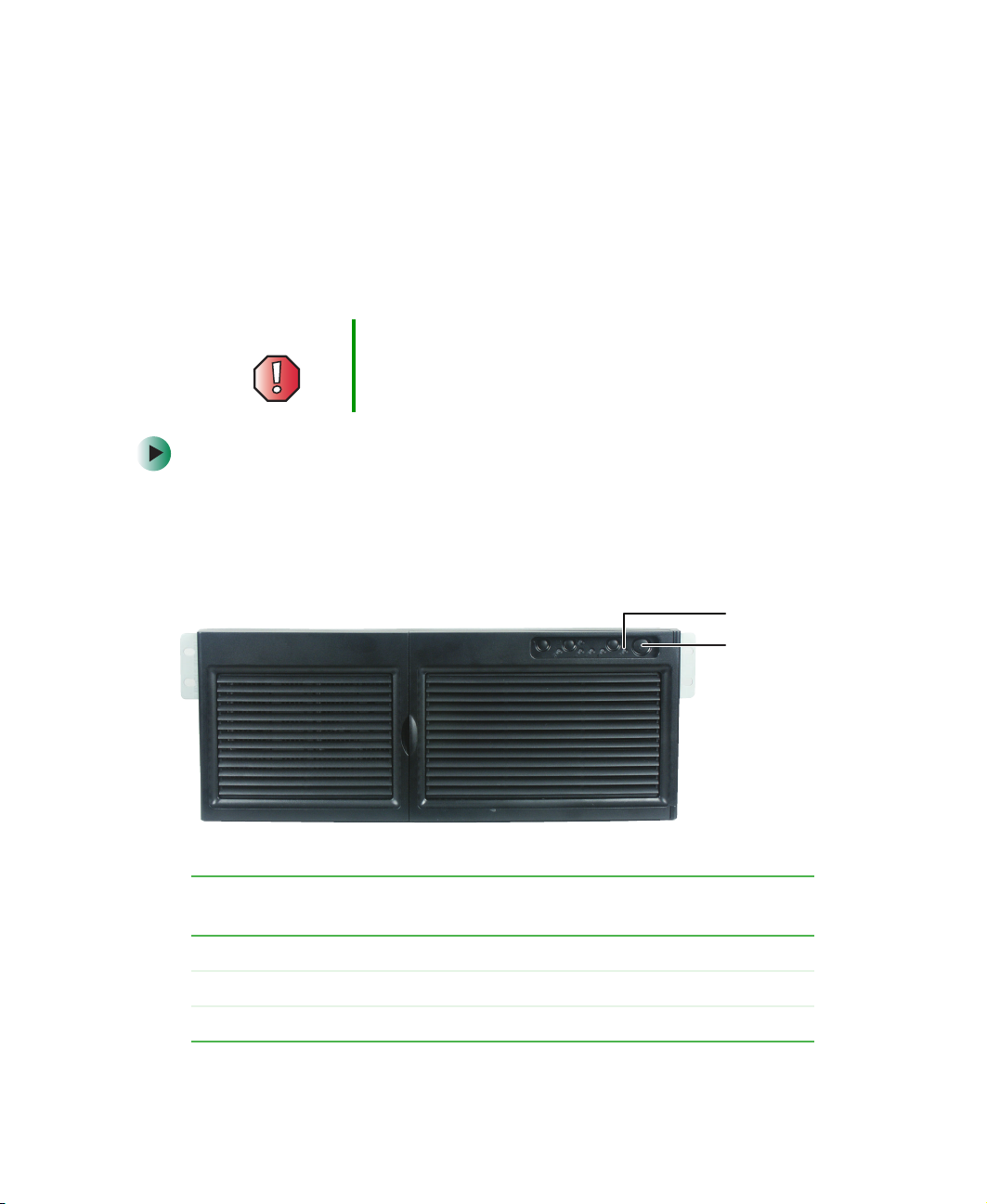
Front
With front cover (door open)
Front panel controls
Sleep button
Serial RJ-45
Tape drive bay
Server ID indicator
Server ID
button
Diskette drive
CD drive
Front panel controls
Hot-swap hard drives
Reset button
Power butto
on-maskable
nterrupt bu tton
System
fault
indicator
2
LAN 1
indicator
LAN 2
indicator
www.gateway.com
Power indicator
Hard drive
activity indicator
Page 9
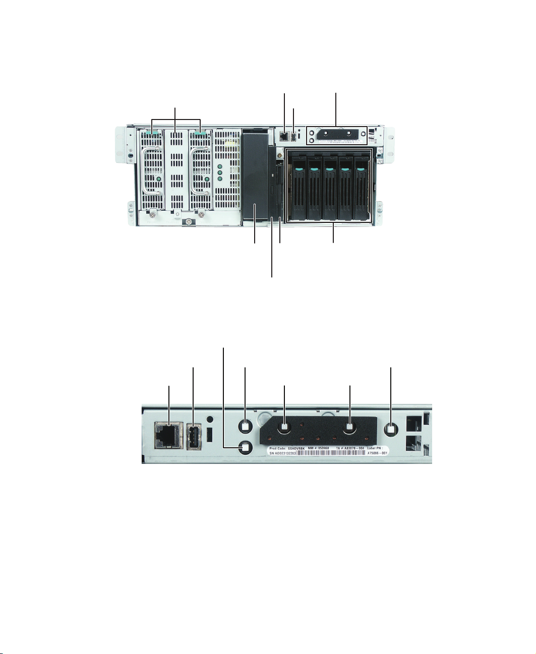
Without front cover
Serial RJ-45 jack
Front panel controls
n
Non-maskable
Front
Power supply bays
Tape drive bay
CD drive (optional)
Diskette
drive
(optional)
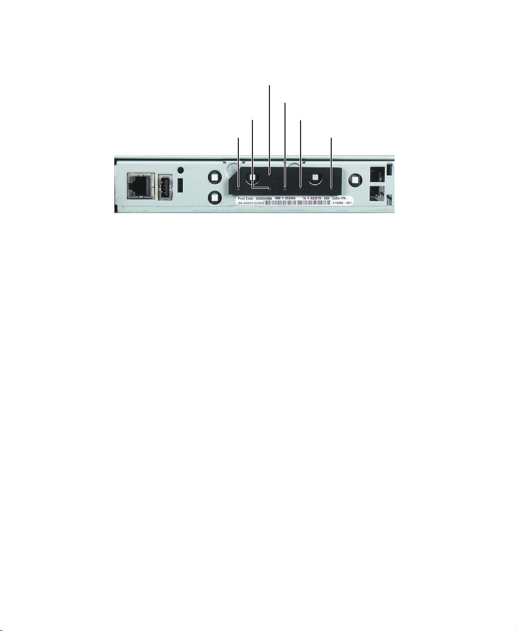
Front panel controls: ports and buttons
interrupt button
USB port
Serial RJ-45 jack
Sleep
button
Server ID
button
USB port
Hot-swap hard drives
Power butto
Reset button
www.gateway.com
3
Page 10
Chapter 1: Checking Out Yo ur Gateway 995 Series S erver
Server ID indicator
Front panel controls: indicators
Hard drive activity indicator
LAN 2 (1 Gb) indicatorLAN 1 (10/100) indicator
System fault indicator
Power indicator
4
www.gateway.com
Page 11
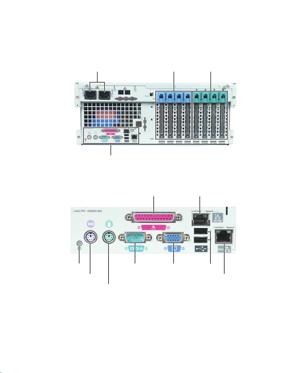
Back
Hot-swap
32-bit and
Parallel port
LAN 1 (10/1 00 Mb) jac k
)
S
i
Back
AC power connections
I/O connectors
I/O connectors
64-bit PCI
expansion
64-bit PCI
expansion
erver ID
ndicator
PS/2
keyboard
port
PS/2 mouse
port
Serial
port
www.gateway.com
VGA
port
USB ports
LAN 2 (10/100/1000 MB
jack
5
Page 12
Chapter 1: Checking Out Yo ur Gateway 995 Series S erver
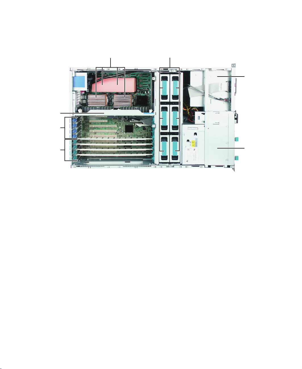
M
Interior
Processor so ckets Fans
emory boar d
32-bit and
64-bit PCI
expansion
Hot-swap
hard drive
cage
Hot-swap
64-bit PCI
expansion
Power
supply
cage
6
www.gateway.com
Page 13
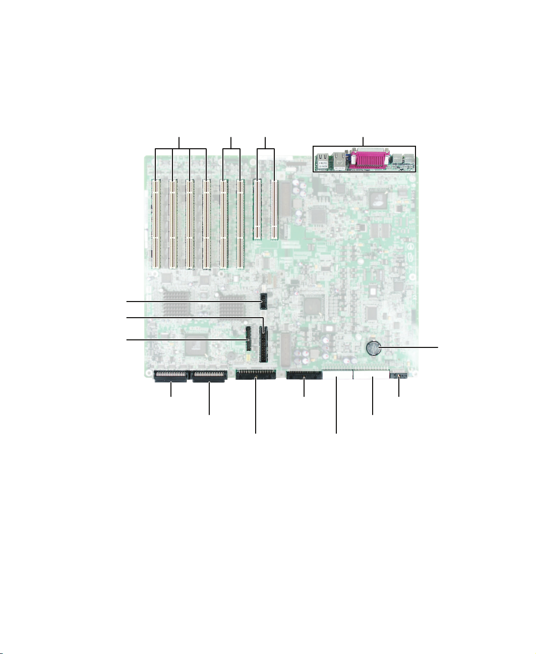
System board
System board
Serial B
port
Front panel
Fan signal
Hot-swap
64-bit PCI
expansion
SCSI
channel A
64-bit PCI
expansion
SCSI
channel B
32-bit PCI
expansion
Diskette
drive
IDE
I/O connectors
CMOS
battery
System board power
control
System board
primary power
System board
secondary
power
www.gateway.com
7
Page 14

Chapter 1: Checking Out Yo ur Gateway 995 Series S erver
Getting Help
In addition to your operating system’s documentation, you can use the
following information resources to help you use your server.
Server Companion CD
The Server Companion CD contains drivers, utilities, and documentation for your
server and related hardware. It can also perform an automated installation of
your Microsoft
Your Server Companion CD.
Gateway Web site
Gateway provides a variety of information on its Web site to help you use your
server.
Visit the Gateway Web site at support.gateway.com for:
■ Technical documentation and product guides
®
Windows® operating system. For more information, see Using
■ Technical tips and support
■ Updated hardware drivers
■ Order status
■ Frequently asked questions (FAQs)
T elephone support
You can access a wide range of services through your telephone, including
customer service, technical support, and information services. For more
information, see “Telephone support” on page 120.
8
www.gateway.com
Page 15

Setting Up Your
Server
Read this chapter to learn how to:
■ Use your server safely
■ Install your server into a cabinet
■ Start and turn off your server
■ Set up your operating system
2
9
Page 16

Chapter 2: Setting Up Y our Server
Setting up the hardware
To make sure that your working environment is safe:
■ Use a clean, dry, stable cabinet mount for your server.
■ Use a UPS with surge protection for protection from power outages and
power spikes.
Warning Your server comes with 3-wire AC power cords fitted with
the correct plug style for your region. If this plug does not
match the connector on your UPS or wall outlet, do not
attempt to modify the plug in any way. Use a UPS or wall
outlet that is appropriate for the supplied AC power cords.
■ Avoid subjecting your server to extreme temperature changes. Do not
expose your server to direct sunlight, heating ducts, or other
heat-generating objects. Damage caused by extreme temperatures is not
covered by your warranty. As a general rule, your server is safest at
temperatures that are comfortable for you.
■ Keep your server and magnetic media away from equipment that
generates magnetic fields, such as unshielded stereo speakers. Strong
magnetic fields can erase data on both diskettes and hard drives. Even a
telephone placed too close to the server may cause interference.
10
Important Keep the server boxes and packing material in case you
need to ship the server.
www.gateway.com
Page 17

Protecting from power source problems
Protecting from power source
problems
Line conditioners and uninterruptible power supplies can help protect your
server against power source problems.
Line conditioners
A line conditioner protects your server from the small fluctuations in voltage
from an electrical supply. Most servers can handle this variation, called line
noise, without problems. However, some electrical sources include more line
noise than normal. Line noise can also be a problem if your server is located
near, or shares a circuit with, a device that causes electromagnetic interference,
such as a television or a motor.
Some uninterruptible power supplies include simple line-conditioning
capabilities.
Uninterruptible power supplies
Use an uninterruptible power supply (UPS) to protect your server from data loss
during a total power failure. A UPS uses a battery to keep your server running
temporarily during a power failure and lets you save your work and shut down
your server. You cannot run your server for an extended period of time while
using only the UPS. Be sure to use a UPS with surge protection. To buy a UPS,
contact Gateway Technical Support, Gateway Sales, or visit
accessories.gateway.com
support, see “Telephone support” on page 120.
. For more information on contacting technical
www.gateway.com
11
Page 18

Chapter 2: Setting Up Y our Server
Mounting your server into a cabinet
To mount your server into a server cabinet, follow the instructions included
in the rail kit box.
Warning To avoid injury when mounting the server into a cabinet,
use only a mechanical lif ting aid or anothe r person to help
lift the server.
Do not try to move or lift the server by the handles on the
power supplies.
12
www.gateway.com
Page 19
Starting your server
Power
Before you start your server for the first time:
■ Make sure that the server and monitor are plugged into a power outlet or
UPS and that the UPS (if you are using one) is turned on.
■ Make sure that all cables are connected securely to the correct ports and
jacks on the back of the server.
Warning When you connect peripheral device s to t he server , m ak e
sure that your server and devices are turned off and the
power cords are unplugged.
To start the server:
1 Connect all peripheral devices to the server, such as a monitor, keyboard,
and mouse.
2 Press the power button.
Starting your server
When the powe r
indicator is...
Green (steady on) The server is turned on.
Green (blinking) The server is in sleep mode.
Off The server is turned off.
It means...
www.gateway.com
indicator
Power
button
13
Page 20

Chapter 2: Setting Up Y our Server
When the syst em
It means...
fault indicator is...
Green (steady on) The server is operating normally.
Green (blinking) The server is operating in a degraded condition.
Orange (steady on) The server is in a critical or unrecoverable condition.
Orange (blinking) The server is in a noncritical condition.
Off POST failure or full system stop.
If nothing happens when you press the power button:
■ Make sure that the power cables are plugged in securely and that your
UPS (if you are using one) is plugged in and turned on.
■ Make sure that the monitor is connected to the server, plugged into
the power outlet or UPS, and turned on. You may also need to adjust
the monitor’s brightness and contrast controls.
■ If you cannot find the cause of the power loss, contact Gateway
Technical Support. For more information, see “Getting Help” on
page 8.
3 The first time you turn on the server, any pre-installed operating system
may begin asking you for configuration settings. See your operating
system’s documentation for instructions on configuring advanced settings
for your specific network.
Understanding the power-on self-test
When you turn on your server, the power-on self-test (POST) routine checks
the server memory and components. If POST finds any problems, the server
displays error messages and emits audible beep codes. Write down any error
messages that you see, then see “Error messages” on page 124 and “Codes” on
page 127 for troubleshooting information.
14
www.gateway.com
Page 21

Starting your server
When you see “Press <F2> to enter Setup” you can press these keys to change
the standard POST routine:
To... ...Press
Abort the memory test during POST
Resume after a POST error is displayed
Enter the BIOS Setup utility during POST
Open the boot menu
Boot from a network using Preboot Execution
Environment (PXE)
Remove the splash sc ree n in ord er to vi ew di agn os tic
messages
Enter the Adaptec SCSISelect Utility during POST
SPACEBAR
F1
F2
F10
F12
ESC
CTRL+A
T urning off your server
Every time you turn off your server, first shut down the operating system. You
may lose data if you do not follow the correct procedure.
To turn off the server:
1 See the operating system’s documentation or online help for instructions
on shutting down the operating system. Whenever possible, you should
use the operating system’s shut down procedure instead of pressing the
power button.
Warning The power button on the server does not turn off server
AC power . To remove AC power from the server, you must
unplug the AC power cords from the wall outlet or power
source. The power cords are considered the disconnect
device to the main (AC) power.
2 If your server did not turn off automatically, press the power button.
- OR -
Press the reset button to reset the server.
www.gateway.com
15
Page 22

Chapter 2: Setting Up Y our Server
Setting up the operating system
If you ordered your server with the operating system already installed by
Gateway, it is completely installed and the basic settings are already configured.
See your operating system’s documentation for instructions on configuring
advanced settings for your specific network.
If you are installing an operating system because it was not already installed
by Gateway, see the appropriate installation guide for instructions. For help in
configuring your operating system, see “Telephone support” on page 120.
Configuring the on-board SCSI controller
Your server has an onboard SCSI controller with two channels (A and B). The
controller includes a configuration utility that lets you configure SCSI controller
and device settings.
To run the SCSI configuration utility:
1 During POST, press CTRL+A when you see “Press <Ctrl><A> for
SCSISelect(TM) Utility”
2 Follow the on-screen instructions to configure settings.
16
www.gateway.com
Page 23

Maintaining Your
Server
Read this chapter to learn how to:
■ Care for your server
■ Record the BIOS configuration
■ Manage your server and network
3
17
Page 24

Chapter 3: Maintaining Y our Server
Caring for your server
To extend the life of your server:
■ Be careful not to bump or drop your server.
■ When transporting your server, we recommend that you put it in the
original packaging materials.
■ Keep your server and magnetic media away from equipment that generates
magnetic fields, such as unshielded speakers.
■ Avoid subjecting your server to extreme temperatures. Do not expose your
server to heating ducts or other heat-generating objects. Damage caused
by extreme temperatures is not covered by your warranty. As a general rule,
your server is safest at temperatures that are comfortable for you.
■ Keep all liquids away from your server. When spilled onto server
components, almost any liquid can result in extremely expensive repairs
that are not covered under your warranty.
■ Avoid dusty or dirty work environments. Dust and dirt can clog the
internal mechanisms and can cause the server to overheat.
Cleaning your server
Keep your server clean and the vents free from dust.
Cleaning tips
■ Always turn off your server and other peripheral devices before cleaning
any components.
Warning When you shut down your server, the power turns off, but
some electrical current still flows through your server. To
avoid possible injury from electrical shock, unplug the
power cords and all other cables connected to the server.
■ Use a damp, lint-free cloth to clean your server and other parts of your
server system. Do not use abrasive or solvent cleaners because they can
damage the finish on components.
■ Keep the cooling vents free of dust. With your server turned off and
unplugged, brush the dust away from the vents with a damp cloth, but
be careful not to drip any water into the vents.
18
www.gateway.com
Page 25

Caring for your server
Cleaning the keyboard
You should clean the keyboard occasionally by using an aerosol can of air with
a narrow, straw-like extension to remove dust and lint trapped under the keys.
If you spill liquid on the keyboard, turn off your server and turn the keyboard
upside down to let the liquid drain. Let the keyboard dry completely before
trying to use it again. If the keyboard does not work after it dries, you may
need to replace it. Keyboard damage resulting from spilled liquids is not covered
by your warranty.
Cleaning the screen
If your computer screen is a flat panel display, use only a damp, soft cloth to
clean it. Never spray water directly onto the screen.
Warning The compute r screen is made of sp ecially coat ed glass
and can be scratched or damaged by abrasive or
ammonia-based glass cleaners.
- OR -
If your computer screen is not a flat panel display, use a soft cloth dampened
with glass cleaner to clean the screen. Never spray cleaner directly onto the
screen.
Cleaning the tape drive
If you use a tape drive to back up your files, regular maintenance will lengthen
the life of the drive. To maintain the drive’s reliability:
■ Clean the drive monthly with the cleaning cartridge included with
the drive.
■ Remove the tape from the drive whenever the drive is not in use.
www.gateway.com
19
Page 26

Chapter 3: Maintaining Y our Server
Preparing for system recovery
If your system files are corrupted, you may not be able to start the server from
the hard drive. Startup diskettes are diskettes that let you start the server and
attempt to fix the problem. See your operating system’s documentation or
online help for instructions on creating startup diskettes.
Some operating systems also let you create an emergency repair diskette to back
up critical operating system files. See your operating system’s documentation
or online help for instructions on creating and using an emergency repair
diskette.
Recording the BIOS configuration
To help keep track of your custom changes to BIOS settings and to prepare for
system recovery, you should record your BIOS configuration after you have your
server set up and working.
To record your BIOS configuration:
20
1 Print the appendix for “BIOS Settings” on page 151.
2 Restart your server, then press F2 when the Gateway logo screen appears
during startup. The BIOS Setup utility opens.
3 Record the BIOS settings on your printout.
www.gateway.com
Page 27

System administrat ion
System administration
Gateway Server Manager
Gateway Server Manager lets you manage multiple computers on a Windows™
network from a single window, then implement commands and policies across
the network with a single action. With Gateway Server Manager, you can run
system management tasks which are triggered by certain events or conditions.
Printed documentation comes with the Gateway Server Manager CD. You can
find additional documentation in the program’s online help.
Server security
Using BIOS security passwords
To prevent unauthorized use of the server, you can set server startup passwords.
Set up an administrator password to prevent unauthorized access to the BIOS
Setup utility.
For information about resetting BIOS passwords, see “Resetting BIOS
passwords” on page 118.
To set the BIOS security passwords:
1 Restart your server, then press F2 when the Gateway logo screen appears
during startup. The BIOS Setup utility opens.
2 Select the Security menu.
3 Select Administrator Password.
4 Type the password and press ENTER, then type it again and press ENTER.
5 Save your changes and close the BIOS Setup utility.
www.gateway.com
21
Page 28

Chapter 3: Maintaining Y our Server
To remove a BIOS security password:
1 Restart your server, then press F2 when the Gateway logo screen appears
during startup. The BIOS Setup utility opens.
2 Select the Security menu, then select the password to remove.
3 Enter the current password, then press ENTER.
4 For the new password, leave the password field blank, then press ENTER.
The password is removed.
Tips & Tricks Passwords can also be cleared using jumpers on the
system board. For instructions, see “Resetting BIOS
passwords” on page118.
22
www.gateway.com
Page 29

Identifying your s erver
Identifying your server
While you are working on a cabinet that contains several servers, it can be
difficult to keep track of which server or servers you are currently working on.
The Server ID indicators are blue LEDs that you can turn on to help you locate
the correct server. For the Server ID indicators to turn on, the server does not
need to be turned on, but it does need to be plugged in. Your server has one
indicator on the front, and one indicator on the back.
To turn on the server indicator:
1 Press the server ID button. The two blue server ID indicators turn on (one
on the front, one on the back).
2 To turn off the indicators, press the server ID button again.
www.gateway.com
23
Page 30

Chapter 3: Maintaining Y our Server
Updating the baseboard management controller firmware
The baseboard management controller (BMC) performs several system
management functions such as:
■ Monitoring server components and sensors
■ Managing nonvolatile storage for the system event log and sensor data
records
■ Interfacing with the emergency management port (serial RJ-45 on the back
panel) and LAN 1 jack to send alerts and interact with remote management
systems.
■ Providing the main front panel controls (such as power and reset).
You should update the BMC firmware only when Gateway Technical Support
has instructed you to update it.
To update the BMC firmware:
24
1 Download the BMC update file from support.gateway.com.
2 Follow the instructions included with the update file.
www.gateway.com
Page 31

Using the System Set up Utility
Using the System Setup Utility
The System Setup Utility (SSU) lets you:
■ View Field Replaceable Unit (FRU) information
■ View sensor data records
■ Set up the server to send alerts for platform events
■ Set up the server for out-of-band (OOB) access through Gateway Server
Manager
Important The SSU do es not work within a DOS window running
under an operating system such as Windows.
Viewing FRU information
To view the Field Replaceable Unit (FRU) information:
1 Boot your server from the Server Companion CD, then select System Setup
Utility
from the menu. The System Setup Utility starts.
2 In the SSU Main window, click FRU Manager. The SSU automatically loads
the current list of events from non-volatile memory.
3 Click the category for Chassis, Board, or Product. The category expands to
show a list of components for that category.
4 Click a component. Information for that component is displayed.
www.gateway.com
25
Page 32

Chapter 3: Maintaining Y our Server
Using the FRU/SDR Load utility
The Field Replaceable Unit and Sensor Data Record (FRU/SDR) load utility is a
program used to update the server’s FRU and SDR information.
To use the FRU/SDR Load utility:
1 Boot your server from the Server Companion CD, then select System Setup
Utility
from the menu. The System Setup Utility starts.
2 Run the frusdr.exe file.
Viewing sensor data records
To view the Sensor Data Records (SDR):
1 Boot your server from the Server Companion CD, then select System Setup
Utility
from the menu. The System Setup Utility starts.
2 In the SSU Main window, click SDR Manager.
3 Click a category in the left pane. The category expands to show a list of
SDRs for that category.
4 Click an SDR. Information for that SDR is displayed.
Setting up remote access
You can set up the server so you can perform system management tasks
remotely.
Setting up remote LAN access
To set up remote LAN access:
1 Boot your server from the Server Companion CD, then select System Setup
Utility
from the menu. The System Setup Utility starts.
2 In the SSU Main window, click Platform Event Manager (PEM).
26
www.gateway.com
Page 33

Using the System Set up Utility
3 In the PEM window, click Configure LAN.
4 To require a password for remote access, type the password in the Enter
New Password
from 1 to 16 characters long, using any number or letter.
To clear the password, leave both boxes blank. You can also clear the
password by clicking
box and in the Verify New Password box. Passwords can be
Options, then Clear LAN Password.
5 Click the remote access mode from the LAN Access Mode list:
■ Always Available—A remote system can initiate a LAN connection
regardless of the state of the server.
■ Restricted—A remote system can initiate a LAN connection, but
cannot perform control operations such as power down, reset, or front
panel NMI (non-maskable interrupt).
■ Disabled—Remote systems are not allowed to initiate LAN
connections.
6 In the IP Setup box, click one:
■ DHCP—The IP address for the server is automatically assigned by the
DHCP (dynamic host control protocol) server on the network. The
Host, Gateway, and Subnet Mask boxes in the dialog box are ignored.
■ Static—Assign the IP address for the server using the Host, Gateway,
and Subnet Mask boxes in the dialog box.
7 If you selected Static in the previous step, complete the IP addressing boxes:
■ Host IP Addres s—The IP address of this server.
■ Gateway IP Address—The IP address of the router for this server.
■ Subnet Mask—The IP address for the server's subnet. The server uses
this to decide if the alert destination is on the same subnet.
8 Click Save to save the changes.
9 Click Close to return to the PEM window.
www.gateway.com
27
Page 34

Chapter 3: Maintaining Y our Server
Setting up remote modem or serial access
To set up remote modem or serial access:
1 Boot your server from the Server Companion CD, then select System Setup
Utility
from the menu. The System Setup Utility starts.
2 In the SSU Main window, click Platform Event Manager (PEM).
3 In the PEM window, click Configure EMP.
4 To require a password for remote access, type the password in the Enter
New Password
from 1 to 16 characters long, using any ASCII character in the range 32-126.
To clear the password, leave both boxes blank. You can also clear the
password by clicking
box and in the Verify New Password box. Passwords can be
Options, then Clear LAN Password.
5 In the Modem Ring Time box, type the number of 500 ms intervals that the
BMC should wait before answering an incoming call. A value greater than
zero gives the BIOS time to answer before the BMC takes control. A value
of zero causes the BMC to answer immediately. The maximum value, 63,
tells the BMC to ignore the call. Modem Ring Time applies only to Preboot
access mode and is ignored for other access modes.
28
6 In the System Phone Number box, type the number for the phone line
connected to the modem on the EMP.
7 In the Access Mode list, click the remote access mode:
■ Always Active—The EMP is available at any time.
■ Preboot—The EMP is available only when the server is powered down
or is running POST during startup. After the operating system is
loaded, a connection cannot be made.
■ Disabled—Remote systems are not allowed to initiate connections.
8 In the Restricted Mode list, click either:
■ Enabled—A remote system can initiate a connection, but cannot
perform control operations such as power down, reset, or front panel
NMI.
■ Disabled—The remote system has full control of the server.
www.gateway.com
Page 35

9 In the Connection Mode list, click either:
■ Direct Connect—The Serial RJ-45 jack on the server is connected by a
serial cable to the remote system.
■ Modem Connect—The Serial RJ-45 jack on the server is connected to a
modem.
10 Click Save to save the changes.
11 Click Close to return to the PEM window.
Setting up paging alerts
To set up paging alerts:
1 Boot your server from the Server Companion CD, then select System Setup
Utility
from the menu. The System Setup Utility starts.
2 Install an external modem on the serial RJ-45 jack on the back of your
server.
Using the System Set up Utility
3 In the SSU Main window, click Platform Event Manager (PEM).
4 In the PEM window, click Configure EMP.
5 In the corresponding boxes, enter the following command strings for the
modem attached to the serial RJ-45 jack:
■ ESC Sequence—The escape sequence. This string is sent to the modem
before sending command strings. The maximum length for the string
is five characters. Longer strings are truncated.
■ Hangup String—Hang up or drop the connection. The EMP
automatically sends an E
maximum length for the string is eight characters.
■ Modem Dial Command—The command to dial a phone number. This
string is sent to the modem before sending the paging string.
■ Modem Init String—Initialization string for the modem. Sent every time
the EMP initializes. You will be notified if the string is truncated.
Following a save, the actual string saved is displayed in the edit box.
NTER character following this string. The
www.gateway.com
29
Page 36

Chapter 3: Maintaining Y our Server
6 Click Save to save the changes.
7 Click Close to return to the PEM window.
8 In the PEM window, click Configure PEP.
9 Click to select the Enable PEP check box.
10 In the Blackout Period box, type the minimum time, in minutes, between
successive pages. The valid range is 0-255 where 0 disables the blackout
period. Setting a blackout period can save you from being flooded with
repeat pages. After you receive a PEP page, no additional pages are sent
by PEP for the duration of the blackout period.
11 In the Paging String box, type the telephone number to dial for the page
and the message you want sent with the page. The maximum length for
the paging string is determined at runtime from firmware. You will be
notified if the string is truncated. Following a save, the actual string saved
is displayed in the edit box.
12 Click Options, then click Configure Event Actions.
13 In the Platform Event Paging Actions window, move the events that you want
to generate an alert to the
Disabled column by clicking the following buttons:
the
Enabled column and move all other events to
■ >> Moves all events from the Enabled list to the Disabled list.
■ > Moves the selected event from the Enabled list to the Disabled list.
■ < Moves the selected event from the Disabled list to the Enabled list.
■ << Moves all events from the Disabled list to the Enabled list.
14 Click Save to save the changes.
15 Click Close to return to the PEP Configuration window.
16 To send a test page to verify that you have correctly configured PEP, click
Options, then click Send Alert.
17 Click Save to save the configuration.
18 Click Close to return to the Platform Event Manager window.
30
www.gateway.com
Page 37

Setting up LAN alerts
To set up LAN alerts:
1 Boot your server from the Server Companion CD, then select System Setup
Utility
from the menu. The System Setup Utility starts.
2 In the SSU Main window, click Platform Event Manager (PEM).
3 In the PEM window, click Configure LAN.
4 Click to select the Enable LAN Alerts check box.
5 In the SNMP Community String box, you can type an optional string for the
community field in the
The string must be from 5 to 16 characters. The default string is
6 In the IP Setup box, click either:
■ DHCP—The IP address for the server is automatically assigned by the
DHCP (dynamic host control protocol) server on the network. The
Host, Gateway, and Subnet Mask boxes in the dialog box are ignored.
■ Static—Assign the IP address for the server using the Host, Gateway,
and Subnet Mask boxes in the dialog box.
Using the System Set up Utility
Header section of the SNMP trap sent for an alert.
PUBLIC.
7 If you chose Static IP Setup in the previous step, complete the IP addressing
boxes:
■ Host IP Addres s—The IP address of this server.
■ Gateway IP Address—The IP address of the router for this server.
■ Subnet Mask—The IP address for the server’s subnet. The server uses
this to decide if the alert destination is on the same subnet.
8 In the Alert IP Address box, complete the IP address of the system you want
the alerts sent to. If you want the alert to be broadcast to an entire subnet,
enter the IP address for the subnet.
9 Click Options, then click Configure Event Actions.
www.gateway.com
31
Page 38

Chapter 3: Maintaining Y our Server
10 In the BMC LAN Alerting Actions window, move the events that you want
to generate an alert to the
Disabled column by clicking the following buttons:
the
■ >> Moves all events from the Enabled list to the Disabled list.
■ > Moves the selected event from the Enabled list to the Disabled list.
■ < Moves the selected event from the Disabled list to Enabled the list.
■ << Moves all events from the Disabled list to the Enabled list.
11 Click Save to save the changes.
12 Click Close to return to the BMC LAN Configuration window.
13 Click Save to save the changes.
14 Click Close to return to the PEM window.
Enabled column and move all other events to
32
www.gateway.com
Page 39

Using your Server Compani on CD
Using your Server Companion CD
Use the Server Companion CD to access file utilities, drivers, and documentation
for your server and its components. For instructions, see Using Your Server
Companion CD.
www.gateway.com
33
Page 40

Chapter 3: Maintaining Y our Server
34
www.gateway.com
Page 41

Installing
Components
Read this chapter to learn how to:
■ Open and close the server case
■ Install drives
■ Install expansion cards and memory modules
■ Install processors and the processor board
■ Replace the power supply
■ Replace the SCSI backplane
■ Replace the fan module
■ Replace the front panel board
■ Replace the air duct
■ Replace the system board and CMOS battery
4
35
Page 42

Chapter 4: Installing Compo nents
Preparing to install components
Selecting a place to work
Work on your server in an area that:
■ Is clean (avoid dusty areas)
■ Is a low-static environment (avoid carpeted areas)
■ Has a stable surface on which to set your server
■ Has enough room to place all of your server parts
■ Is near a grounded outlet so you can test your server after installation
■ Is near a telephone (in case you need help from Gateway Technical
Support). The telephone must be directly connected to a telephone jack
and cannot be connected to your server.
Preventing static electricity discharge
The components inside your server are extremely sensitive to static electricity,
also known as electrostatic discharge (ESD).
Warning ESD can permanently damage electrostatic
discharge- sensitiv e component s in the se rver. Prevent
ESD damage by following ESD guidelines every time you
open the server case.
Warning To avoid exposure to dangerous electrical voltages and
moving parts, turn off your server and unplug the power
cords and modem cabl e before opening th e server c ase.
Important The power s upply cord s are the m ain disco nnect dev ice
for AC power.
36
www.gateway.com
Page 43

Before working with server components, follow these guidelines:
■ Turn off the server, then unplug the power cords and all other cables.
■ Press the power button to drain any residual power from the server.
■ Wear a grounding wrist strap (available at most electronics stores) and
attach it to a bare metal part of the server. You can also touch a bare metal
surface on the back of the server with your finger.
■ Avoid static-causing surfaces such as carpeted floors, plastic, and packing
foam.
■ Avoid working on the server when your work area is extremely humid.
■ Remove components from their antistatic bags only when you are ready
to use them. Do not lay components on the outside of antistatic bags
because only the inside of the bags provide electrostatic protection.
■ Always hold expansion cards by their edges or their metal mounting
brackets. Avoid touching the edge connectors and components on the
cards. Never slide expansion cards or components over any surface.
Gathering the tools you need
Preparing to instal l components
Some tools and supplies that you may need to work on your server are:
■ A notebook to take notes
■ A Phillips screwdriver
■ A small flat-blade screwdriver
■ Small containers to store various types of screws
■ A grounding wrist strap (available at most electronic stores)
Getting Help
If you have questions about performing any of these procedures, contact
Gateway Technical Support. For more information, see “Getting Help” on
page 8.
www.gateway.com
37
Page 44

Chapter 4: Installing Compo nents
Installing the server handles
The handles help you hold the server while sliding it out of the cabinet for
servicing. Installing the server handles is usually performed as part of the
procedure for installing the server into a cabinet. For more information, see
the Gateway 995 Series Server Rack Installation Guide.
To install the handles:
1 Line up the screw holes on each handle with the corresponding holes on
the front of the server.
38
2 Insert and tighten two screws for each handle. The screws come in a small
bag with the handles.
www.gateway.com
Page 45

Using the front cover
Remove the front cover to access hot-swap power supplies.
To install the front cover:
■ Line up the cover with the front of the server, then press it into place.
To remove the front cover:
■ Grasp the cover and pull it away from the server. You can pull it straight
out or from either side.
Using the front cover
www.gateway.com
39
Page 46

Chapter 4: Installing Compo nents
Opening the front cover door
Open the front cover door to access these components:
■ Hot-swap hard drives
■ Tap e drive
■ CD drive
■ Diskette drive
To open the front cover door:
1 Grasp the finger hold on the left side of the door, then swing the door
open to the right.
40
www.gateway.com
Page 47

Opening the server case
Warning For correct cooling a nd ai r flow, always operate the server
with all panels in place, except while replacing hot-swap
component s. Operat ing the ser ver with out the pa nel in
place wil l cause t he serve r to over heat.
Removing the top rear panel
Remove the top rear panel to access these components:
■ Hot-swap PCI cards
■ Fans and fan cage
■ Inside panel
Important If you are accessing only the internal hot-swap
components, you do not need to disconn ect power before
removing the top rear panel.
Opening the server case
Warning For correct cooling, always install all panels before run ning
the server for an extended time. Operating the server for
longer than five minutes without the panels in place can
overheat and damage the server.
www.gateway.com
41
Page 48

Chapter 4: Installing Compo nents
Screws
To remove the top rear panel:
1 Loosen the two screws that secure the panel to the server.
2 Slide the panel toward the back of the server about one inch, then lift the
panel away from the server.
42
3 To remove the inside panel, see “Removing the inside panel” on page 45.
www.gateway.com
Page 49

Removing the top front panel
Remove the top front panel to access these components:
■ Hot-swap hard drive cage
■ Hot-swap power supply cage
■ Tap e drive
■ CD and diskette drives
■ Front panel board
Warning For correct cooling, alwa ys install all panels bef ore running
the server for an extended time. Operating the server for
longer than five minutes without the panels in place can
overheat and damage the server.
To remove the top front panel:
1 Follow the instructions in “Preventing static electricity discharge” on
page 36. Make sure that you turn off the server, then unplug the power
cords and all other cables connected to the server.
Opening the server case
Warning This server has two power cords. To disconnect internal
AC power, you must unplug both power cords.
2 Remove the front cover, if installed. For instructions, see “Using the front
cover” on page 39.
www.gateway.com
43
Page 50

Chapter 4: Installing Compo nents
Screws
3 Remove the three screws that secure the panel to the server.
4 Press down slightly on the panel while sliding it toward the front of the
server about one inch, then lift the panel away from the server.
44
www.gateway.com
Page 51

Removing the in side panel
Remove the inside panel to access these components:
■ Memory board and memory modules
■ Processor board and processors
■ Standard PCI cards and card slots
■ System board
Warning For correct cooling, always install all panels before run ning
the server for an extended time. Operating the server for
longer than five minutes without the panels in place can
overheat and damage the server.
To remove the inside panel:
1 Follow the instructions in “Preventing static electricity discharge” on
page 36. Make sure that you turn off the server, then unplug the power
cords and all other cables connected to the server.
Opening the server case
Warning This server has two power cords. To disconnect internal
AC power, you must unplug both power cords.
2 Remove the top rear panel. For instructions, see “Removing the top rear
panel” on page 41.
www.gateway.com
45
Page 52

Chapter 4: Installing Compo nents
3 Loosen the two screws that secure the inside panel to the server.
Screws
4 Lift the panel away from the server.
46
www.gateway.com
Page 53

Installing power supply components
Installing power supply
components
Replacing a hot-swap power supply
Your server uses 430 W hot-swappable power supply modules. If your server
has all three power supply modules installed, the modules act as redundant,
hot-swappable power supplies. If one of the three power supplies fails, the other
power supplies support the server while you replace the failed power supply.
You do not need to turn off the server or disconnect peripheral devices to
replace a failed redundant power supply.
Warning If only two power supplies are installed (non-redundant),
you must turn off al l po we r to th e ser ver b efo re rep lac ing
a power supply.
The power supplies in this server contains no
user-serviceable parts. Only a qualified computer
technician should service the power supplies.
Your server comes with 3-wire AC power cords fitted with
the correct plug style for your region. If this plug does not
match the connector on your UPS or wall outlet, do not
attempt to modify the plug in any way. Use a UPS or wall
outlet that is appropriate for the supplied AC power cords.
To replace a power supply:
1 If only two power supplies are installed, follow the instructions in
“Preventing static electricity discharge” on page 36. Make sure that you
turn off the server, then unplug the power cords and all other cables
connected to the server.
2 Remove the front cover, if installed. For instructions, see “Using the front
cover” on page 39.
3 Identify the failed power supply. On a failed power supply, the power
supply’s LED is off.
www.gateway.com
47
Page 54

Chapter 4: Installing Compo nents
4 For help in diagnosing a power supply problem, you can also examine the
cluster of three LEDs to the right of the power supplies.
■ The top LED indicates the left power supply is connected to AC power
and is functioning correctly.
■ The center LED indicates a center power supply is installed and the
server is operating in redundant power mode.
■ The bottom LED indicates the right power supply is connected to
AC power and is functioning correctly.
If any of these LEDs are not on, it may indicate a problem with the power
cords or power distribution board (contained in the power supply cage).
For instructions on replacing the power supply cage, see “Replacing the
power supply cage” on page 52.
Left power
supply status
Center power
supply status
48
Right power
supply status
www.gateway.com
Page 55

Installing power supply components
5 Loosen the screw at the bottom of the failed power supply. Only two power
supplies are shown here.
Screws
6 Rotate the handle of the failed power supply outward until you can grab
onto it securely with your hand.
www.gateway.com
49
Page 56

Chapter 4: Installing Compo nents
Warning Do not try to move or lift the server by the power supply
7 While holding the handle, press the power supply release lever with your
thumb, then pull the power supply out of the server.
handles.
50
8 Insert the new power supply into the vacant slot, then press it all the way
in until it is flush with the front of the server.
Warning If you are not installing a replacement module, you must
install a power sup ply slot cove r to maintain co rrect air flow
and cooling. For instructions, see “Adding a redundant
power supply” on page 51.
9 Fold the power supply handle against the face of the power supply, then
tighten the screw. The screw does not have to be tightened for the power
supply to function correctly.
www.gateway.com
Page 57

Installing power supply components
Adding a redundant pow er supply
To add a third (redundant) power supply:
1 Remove the front cover, if installed. For instructions, see “Using the front
cover” on page 39.
2 Remove the screw that secures the redundant slot’s cover to the server, then
remove the slot cover.
Screw
3 Insert the new power supply into the vacant slot, then press it all the way
in until it clicks into place.
4 If you have added a third power supply to the server for the first time,
you must run the FRU/SDR utility for the server to use it as a redundant
power supply. For instructions on running the FRU/SDR utility, see “Using
the FRU/SDR Load utility” on page 26.
www.gateway.com
51
Page 58

Chapter 4: Installing Compo nents
Replacing the power supply cage
Replacing a power supply cage may require the help of a qualified service
technician.
To replace the power supply cage:
1 Follow the instructions in “Preventing static electricity discharge” on
page 36. Make sure that you turn off the server, then unplug the power
cords and all other cables connected to the server.
2 Remove all of the power supplies. For instructions, see “Replacing a
hot-swap power supply” on page 47.
3 Remove the top rear panel, the top front panel, and the inside panel. For
instructions, see “Removing the top rear panel” on page 41, “Removing
the top front panel” on page 43, and “Removing the inside panel” on
page 45.
4 Remove the fans and fan cage. For instructions, see “Replacing a fan” on
page 58 and “Replacing the fan cage” on page 59.
5 Remove all full-length expansion cards. For instructions, see “Replacing a
hot-swap expansion card” on page 82 and “Replacing a standard expansion
card” on page 84.
52
6 Unplug all cables from the system board. For instructions, see “Replacing
the system board” on page 105.
7 Unplug all power cables from the CD drive, diskette drive, tape drive (if
any are installed) and the hot-swap hard drive cage.
www.gateway.com
Page 59

Installing power supply components
Screw
8 Remove the screw that secures the AC power plug module to the back of
the server.
9 Remove the plug module from the back of the server by lifting it up ¼ inch,
then pulling it toward the front of the server. Let the module hang over
the side of the server.
www.gateway.com
53
Page 60

Chapter 4: Installing Compo nents
10 Remove the four screws that secure the electronics bay to the server.
11 Slide the electronics bay toward the back of the server until the bay is
completely removed.
ScrewsScrews
54
www.gateway.com
Page 61

Installing power supply components
Screws
12 Remove the plug module’s cable from the cable guides inside the server.
Cable
guides
13 Remove the four screws (two on each side) that secure the front support
bracket to the server.
www.gateway.com
Screws
55
Page 62

Chapter 4: Installing Compo nents
14 Remove the support bracket by sliding it toward the front of the server.
15 Loosen the captive screw that secures the power supply cage to the server.
56
Screw
Warning Make sure that all cables from the power supply cage are
disconnected from server components.
www.gateway.com
Page 63

Installing power supply components
16 Slide the power supply cage forward until it stops (about ½ inch), then
lift it away from the server.
17 Insert the new power supply cage into the cage bay, then slide it back until
it stops (about ½ inch).
18 Reinstall the front bracket onto the server, then reinstall the four screws
that secure the bracket to the server.
19 Insert the plug module’s cable into the cable guides inside the server.
20 Insert the electronics bay part-way into the back of the server, keeping the
plug module in the slot.
21 Thread the plug module’s cable into the slot on the side of the electronics
bay, then slide the electronics bay all the way into the server.
22 Reinsert the four screws that secure the electronics bay to the server.
23 Reinstall the plug module onto the back of the server, then reinstall the
screw that secures the plug module to the server.
24 Plug all cables back into the system board, the hot-swap hard drive cage,
the combination drive, and the tape drive (if installed).
25 Reinstall the fan cage, then reinstall each of the six fans.
26 Reinstall all panels, then reinstall all power supplies into the power supply
cage.
www.gateway.com
57
Page 64

Chapter 4: Installing Compo nents
Installing fan components
Replacing a fan
Warning To maintain correct air flow and cooling, never remove a
fan without immediately installing a replacement.
To replace a hot-swap fan:
1 Remove the top rear panel. For instructions, see “Removing the top rear
panel” on page 41.
2 Identify the failed fan. The fan fault indicator points to the failed fan while
the server is on. A failed fan is also indicated by the system fault indicator
on the server front panel.
58
Fan fault
indicators
www.gateway.com
Page 65

Installing fan compone nts
3 Pull the failed fan out of the server, then insert the new fan in its place.
Make sure that the arrow on the top of the fan points toward the back of
the server.
The fan fault indicator turns off.
4 Reinstall the top rear panel.
Replacing the fan cage
To replace the fan cage:
1 Follow the instructions in “Preventing static electricity discharge” on
page 36. Make sure that you turn off the server, then unplug the power
cords and all other cables connected to the server.
2 Remove the top rear panel. For instructions, see “Removing the top rear
panel” on page 41.
www.gateway.com
59
Page 66

Chapter 4: Installing Compo nents
Screws
3 Pull each fan out of the server.
4 Loosen the two captive screws on each end of the fan cage.
60
www.gateway.com
Page 67

Installing fan compone nts
5 Lift the fan cage out of the server, then unplug the two cables from the
fan cage.
6 Plug the cables into the new fan cage, then insert the new cage into the
server.
7 Tighten the two captive screws on each end of the fan cage.
8 Reinstall the fan modules.
9 Reinstall the top rear panel.
Replacing the fan cage board
To replace the fan cage board:
1 Follow the instructions in “Preventing static electricity discharge” on
page 36. Make sure that you turn off the server, then unplug the power
cords and all other cables connected to the server.
2 Remove the fan cage from the server. For instructions, see “Replacing the
fan cage” on page 59.
www.gateway.com
61
Page 68

Chapter 4: Installing Compo nents
Screws
3 Remove the two screws that secure the fan cage board housing to the fan
cage.
4 Lift the board housing away from the fan cage.
62
www.gateway.com
Page 69

Installing fan compone nts
Screws
5 Remove the four screws that secure the board to the board housing.
6 Pry the board away from the housing.
7 Press the new board onto the housing, then reinstall the four screws that
secure the board to the board housing.
8 Reinstall the board housing onto the fan cage.
9 Reinstall the four screws that secure the board housing to the fan cage.
10 Reinstall the fan cage into the server, then reinstall each of the six fans.
11 Reinstall the top rear panel.
www.gateway.com
63
Page 70

Chapter 4: Installing Compo nents
Installing drives
Your server can contain as many as five SCSI hard drives. A tape backup drive,
CD drive, and diskette drive may also be included.
As you prepare to install drives, remember:
■ Before you install a drive, see the drive’s documentation for information
on configuring the drive, setting drive jumpers, and attaching cables.
■ You may need to configure the drives you install using the BIOS Setup
utility. Press F2 at startup to open the BIOS Setup utility.
Replacing a hot-swap hard dri ve
Use this procedure to add or replace hard drives in the hot-swap bay. Your server
supports as many as five 1-inch high 3.5-inch SCA SCSI hard drives. You can
purchase additional SCSI drives through your Gateway Sales or Technical
Support representative.
64
Drive 4
Drive 3
www.gateway.com
Drive 0
Drive 1
Drive 2
Page 71

Important Gateway tests and verifie s the operatio n and compati bility
of the drives it sells. Especially in a hot-swap or
mission-critical environment, additional or replacement
drives must conform to Gateway standards.
To replace a hot-swap hard drive:
1 Open the front cover door (if cover is installed).
Installing drives
Caution Before you remove a failed drive, use the appropriate
software and utilities installed on the server to stop all
activity on the failed drive. Instructions for using the
software are provided by the software manufacturer.
Failure to do so may destroy th e data on th e drive.
www.gateway.com
65
Page 72

Chapter 4: Installing Compo nents
2 Identify the failed hard drive. A failed drive’s status indicator is yellow.
3 Press the green release button on the hot-swap tray lever, then swing the
lever open all the way.
Hard drive status
indicators
66
www.gateway.com
Page 73

Installing drives
Screw
4 Pull the tray straight out of the server.
5 If you are replacing a hard drive, remove the four screws that secure the
old hard drive to the drive tray, then remove the drive from the tray.
Screw
- OR -
www.gateway.com
Screw
Screw
67
Page 74

Chapter 4: Installing Compo nents
Screw
If you are adding a new drive, remove the four screws that secure the hard
drive spacer to the drive tray, then remove the spacer from the tray.
Screw
6 Line up the screw holes in the new drive with the holes in the side of the
drive tray, then secure the drive to the tray with the four screws you
removed in Step 5.
Screw
Screw
7 Make sure that the tray’s release lever is open, then slide the new drive
into the empty hot-swap bay.
8 Close the drive’s release lever.
Replacing the hot-swap hard drive cage
To replace the hot-swap hard drive cage:
1 Follow the instructions in “Preventing static electricity discharge” on
page 36. Make sure that you turn off the server, then unplug the power
cords and all other cables connected to the server.
2 Remove the front cover, if installed. For instructions, see “To remove the
front cover:” on page 39.
68
www.gateway.com
Page 75

Installing drives
3 Remove each of the hot-swap hard drives. Make note of the slot each drive
is removed from. For instructions, see “Replacing a hot-swap hard drive”
on page 64.
4 Remove the top front panel. For instructions, see “Removing the top front
panel” on page 43.
5 Disconnect the SCSI ribbon cable and the three power cables from the back
of the cage.
6 Press the tab on each side of the drive cage with a small, flat tool such as
a scribe or a flat screwdriver.
www.gateway.com
69
Page 76

Chapter 4: Installing Compo nents
7 Slide the cage out of the server toward the front.
8 Slide the new hard drive cage into the cage bay until it clicks into place.
9 Reconnect the three power cables and one SCSI ribbon cable to the back
of the cage.
10 Reinstall each hard drive into the slot it was removed from, then reinstall
each panel that was removed.
Installing a tape drive
Warning Although the tape drive bay is capable of holding a hard
drive, to maintain correct cooling you should not install a
hard drive in this bay.
To install a tape drive:
1 Follow the instructions in “Preventing static electricity discharge” on
page 36. Make sure that you turn off the server, then unplug the power
cords and all other cables connected to the server.
2 Remove the front cover, if installed. For instructions, see “Using the front
cover” on page 39.
70
www.gateway.com
Page 77

Installing drives
3 Press the tabs on each side of the tape drive bay’s spacer, then pull the
spacer out of the server.
www.gateway.com
71
Page 78

Chapter 4: Installing Compo nents
Screws
Screws
4 Remove the two screws that secure each slide rail to the spacer, then
remove the slide rails.
5 Attach each rail onto the tape drive using tape drive mounting screws
shipped with your server.
Screws
72
Screws
www.gateway.com
Page 79

Installing drives
6 Slide the tape drive into the tape drive bay until its front is flush with the
front of the server.
7 Remove the top front panel from the server. For instructions, see
“Removing the top front panel” on page 43.
8 Remove all six fans from the fan cage. For instructions, see “Replacing a
fan” on page 58.
9 Remove the fan cage. For instructions, see “Replacing the fan cage” on
page 59.
10 Plug a power cable and an SCSI cable into the back of the tape drive.
11 Reinstall the fan cage, then reinstall all six fans.
12 Reinstall the top front panel onto the server.
www.gateway.com
73
Page 80

Chapter 4: Installing Compo nents
Replacing the media drive bracket
The media drive bracket contains the optional media drives (CD drive and
diskette drive).
Caution The drives in the media drive bracket are not
hot-swappable. Before removing the bracket, make sure
that the server is turned off and power cords are
unplugged.
To replace the media drive bracket:
1 Follow the instructions in “Preventing static electricity discharge” on
page 36. Make sure that you turn off the server, then unplug the power
cords and all other cables connected to the server.
2 Remove the top rear panel. For instructions, see “Removing the top rear
panel” on page 41.
3 Remove the top front panel. For instructions, see “Removing the top front
panel” on page 43.
4 Remove the fans and the fan cage. For instructions, see “Replacing a fan”
on page 58 and “Replacing the fan cage” on page 59.
5 Unplug the power and data cables that connect to the media drive bracket.
6 Remove the screw that secures the media drive bracket to the server.
Screw
74
www.gateway.com
Page 81

Installing drives
7 Pull the bracket out of the server toward the front.
8 Insert the new bracket into the server, then reinstall the screw.
9 Reconnect the power and data cables to the bracket, then reinstall the fan
cage and fans.
10 Reinstall the top front and top rear panels.
Replacing the CD drive
Warning The drives in the media drive bracket are not
hot-swappable. Before removing the bracket, make sure
that the server is turned off and power cords are
unplugged.
To replace the CD drive:
1 Follow the instructions in “Preventing static electricity discharge” on
page 36. Make sure that you turn off the server, then unplug the power
cords and all other cables connected to the server.
2 Remove the media drive bracket. For instructions, see “Replacing the media
drive bracket” on page 74.
www.gateway.com
75
Page 82

Chapter 4: Installing Compo nents
3 Remove the CD drive from the bracket by pulling the side nearest the screw
hole.
4 Insert the new CD drive onto the bracket so the screw holes on the upper
left edge of the drive line up with the alignment pins on the bracket, then
press the drive down onto the bracket until it snaps into place.
Screw hole
76
Screw hole
Alignment pin
5 Reinstall the media drive bracket into the server. For instructions, see
“Replacing the media drive bracket” on page 74.
www.gateway.com
Page 83

Replacing the diskette drive
Warning The drives in the media drive bracket are not
hot-swappable. Before removing the bracket, make sure
that the server is turned off and power cords are
unplugged.
To replace the diskette drive:
1 Follow the instructions in “Preventing static electricity discharge” on
page 36. Make sure that you turn off the server, then unplug the power
cords and all other cables connected to the server.
2 Remove the media drive bracket. For instructions, see “Replacing the media
drive bracket” on page 74.
3 Remove the CD drive. For instructions, see “Replacing the CD drive” on
page 75.
4 Lift the ribbon cable’s locking bar away from the ribbon cable by lifting
the two tabs on either side of the bar.
Installing drives
Locking bar
tabs
5 Remove the ribbon cable from the connector on the drive.
www.gateway.com
77
Page 84

Chapter 4: Installing Compo nents
w
6 Remove the diskette drive from the bracket by pulling the side nearest the
screw hole.
7 Insert the new diskette drive into the bracket.
8 Reconnect the ribbon cable into the connector on the diskette drive, then
lock the ribbon cable into place by pressing on the locking bar tabs.
9 Reinstall the CD drive, then reinstall the media drive bracket into the
server. For instructions, see “Replacing the media drive bracket” on
page 74.
Scre
hole
78
www.gateway.com
Page 85

Installing expans ion cards
Installing expansion cards
Installing an expansion card
When you are installing an expansion card into a slot for the first time, the
server must be turned off, even if you are installing the card into a hot-swap
card slot. If you are replacing an existing card, see “Replacing a hot-swap
expansion card” on page 82 or “Replacing a standard expansion card” on
page 84.
32-bit PCI
expansion
slots
64-bit PCI
expansion slots
Hot-swap 64-bit PCI
expansion slots
To install an expansion card:
1 Follow the instructions in “Preventing static electricity discharge” on
page 36. Make sure that you turn off the server, then unplug the power
cords and all other cables connected to the server.
2 If you are installing a card into a standard PCI card slot, remove the inside
panel. For instructions, see “Removing the inside panel” on page 45.
www.gateway.com
79
Page 86

Chapter 4: Installing Compo nents
3 Press down on the card slot’s locking clip, then rotate the clip out of the
way toward the back of the server.
4 Push out the card slot’s EMI shield.
80
www.gateway.com
Page 87

Installing expans ion cards
5 Insert the card into the card slot. If the card is a full-length card, make
sure that the end of the card slides into the full-length card guide next to
the fan cage.
6 From the back of the server, press the card’s locking clip in until it clicks
into place.
7 Reinstall all panels.
www.gateway.com
81
Page 88

Chapter 4: Installing Compo nents
Replacing a hot-swap expansion card
Expansion cards installed in PCI card slots 5 through 8 can be replaced while
the server is on. If you are installing a card into the slot for the first time, see
“Installing an expansion card” on page 79 for instructions.
Caution When hot-swapping a card, the failed card must be
replaced by an identical c ard. If the card is a dif ferent type ,
turn off the server and disconnect power before changing
cards.
To replace a hot-swap expansion card:
1 Remove the top rear panel. For instructions, see “Removing the top rear
panel” on page 41.
2 Identify the failed expansion card. A green LED indicator above the card
means the card is functioning normally, and a yellow LED indicator means
the card has failed.
82
Card operating
correctly
Card has failed
www.gateway.com
Page 89

Installing expans ion cards
3 Press down on the expansion card’s locking clip, then rotate the clip up
and out of the way.
4 Disconnect any cables attached to the card.
5 Remove the card from the server.
6 Insert the new card into the same slot you removed the old card from. If
the card is a full-length card, make sure that the end of the card slides into
the full-length card guide next to the fan cage.
www.gateway.com
83
Page 90

Chapter 4: Installing Compo nents
7 From the back of the server, press the card’s locking clip in until it clicks
into place.
8 Reinstall the top rear panel.
Replacing a standard expansion card
The server must be off when you install expansion cards into PCI card slots
1through 4.
Warning Standard expansion cards cannot be replaced while the
server is on.
To replace an expansion card:
1 Follow the instructions in “Preventing static electricity discharge” on
page 36. Make sure that you turn off the server, then unplug the power
cords and all other cables connected to the server.
2 Remove the inside panel. For instructions, see “Removing the inside panel”
on page 45.
3 Disconnect any cables attached to the card.
4 Press down on the expansion card’s locking clip, then rotate the clip up
and out of the way.
84
www.gateway.com
Page 91

Installing expans ion cards
5 Remove the card from the server.
6 Insert the new card into the same slot you removed the old card from. If
the card is a full-length card, make sure that the end of the card slides into
the full-length card guide next to the fan cage.
7 From the back of the server, press the card’s locking clip in until it clicks
into place.
8 Reinstall all panels.
www.gateway.com
85
Page 92

Chapter 4: Installing Compo nents
Installing memory
Your server supports from 512 MB to 24 GB total memory.
Caution Modules must be installed in identical groups of four. Use
only PC1600 (DDR-200) or PC2100 (DDR-266) compliant,
SDRAM register ed ECC, DIMM memory mo dules.
Install memory first into Bank 1, Bank 2, then Bank 3. If
memory is installed incorrectly, your server will not start.
Partially filled banks are ignored by the server.
For the most reli able and s table operat ion, we re commend
you use memory from the same manufacturer in all
memory banks.
Bank 3
Bank 2
Bank 1
To add or replace memory modules:
1 Follow the instructions in “Preventing static electricity discharge” on
page 36. Make sure that you turn off the server, then unplug the power
cords and all other cables connected to the server.
2 Remove the top rear panel. For instructions, see “Removing the top rear
panel” on page 41.
3 Remove the inside panel. For instructions, see “Removing the inside panel”
on page 45.
86
www.gateway.com
Page 93

Installing memor y
4 Grasp the top of the memory board at the blue tabs, then pull the memory
board out of the server.
5 Lay the memory board onto a flat surface before removing or installing
memory modules. For more information on selecting a place to work, see
“Selecting a place to work” on page 36.
6 If you are replacing a memory module, pull the locking clips away from
the old module, then pull the module out of the memory slot.
7 Align the notch on the new memory module with the notch in a vacant
module slot, then press it firmly into the slot. The tabs on the sides of the
memory slot should secure the memory module automatically.
www.gateway.com
87
Page 94

Chapter 4: Installing Compo nents
Memory board guides
Important Install memory first into Bank 1, Bank 2, then Bank 3. If
8 Reinstall the memory board into the server. Make sure that the edges of
the board slide into the memory board guides inside the server.
memory is installed incorrectly, your server will not start.
Partially filled banks are ignored by the server.
9 Reinstall all panels.
10 Turn on the server, then make sure that the operating system completely
loads. If you receive an error, see “Memory” on page 141.
88
www.gateway.com
Page 95

Replacing the front pa nel board
Replacing the front panel board
The front panel board contains the actual LEDs, buttons, and ports that are
accessed from the front panel of your server.
To replace the front panel board:
1 Follow the instructions in “Preventing static electricity discharge” on
page 36. Make sure that you turn off the server, then unplug the power
cords and all other cables connected to the server.
2 Remove the top rear panel. For instructions, see “Removing the top rear
panel” on page 41.
3 Remove the top front panel. For instructions, see “Removing the top front
panel” on page 43.
4 Unplug the three cables that are connected to the front panel board.
www.gateway.com
89
Page 96

Chapter 4: Installing Compo nents
Screw
5 Remove the screw that secures the front panel board to the server.
6 Pull the board away from the server by prying on the side closest to the
standoff.
Standoff
7 Insert the new front panel board behind the board guide slot on the right
edge of the front panel bay.
8 Press the board into place over the standoff, then reinstall the screw.
9 Reconnect the three cables.
10 Replace the panels.
90
Board
guide
slot
www.gateway.com
Page 97

Replacing the air duct
Screw
To remove the processor air duct:
1 Follow the instructions in “Preventing static electricity discharge” on
page 36. Make sure that you turn off the server, then unplug the power
cords and all other cables connected to the server.
2 Remove the top rear panel. For instructions, see “Removing the top rear
panel” on page 41.
3 Remove the inside panel. For instructions, see “Removing the inside panel”
on page 45.
4 Remove the screw that secures the AC power plug module to the back of
the server.
Replacing the air duct
www.gateway.com
91
Page 98

Chapter 4: Installing Compo nents
5 Remove the plug module from the back of the server by lifting it up 1/4
inch, then pulling it toward the front of the server. Let the module hang
over the side of the server.
a
6 Remove the memory board from the server. For instructions, see “Installing
memory” on page 86.
7 Press the two air duct retention clips together.
92
www.gateway.com
Page 99

Replacing the air duct
8 While holding the retention clips together, rotate the air duct away from
the server, then lift off the air duct.
9 Insert the front of the new air duct into the server, then rotate the back
of the air duct downward until it snaps into place.
10 Reinstall the AC power plug module, then reinstall all panels.
www.gateway.com
93
Page 100

Chapter 4: Installing Compo nents
Processor board
Replacing the processor board
To remove the processor board:
1 Follow the instructions in “Preventing static electricity discharge” on
page 36. Make sure that you turn off the server, then unplug the power
cords and all other cables connected to the server.
2 Remove the top rear panel. For instructions, see “Removing the top rear
panel” on page 41.
3 Remove the inside panel. For instructions, see “Removing the inside panel”
on page 45.
4 Remove the air duct. For instructions, see “Replacing the air duct” on
page 91.
5 Rotate the processor board release levers until they are nearly vertical.
release levers
94
www.gateway.com
 Loading...