

Page 1

User Guide
Gateway 9515 Server
Page 2

Contents
1 Checking Out Your Gateway Server. . . . . . . . . . . . . . . . . . . . . . . . . . . . . . . . . . . . 1
Front . . . . . . . . . . . . . . . . . . . . . . . . . . . . . . . . . . . . . . . . . . . . . . . . . . . . . . . . . . . . . . . . . . . . 2
Control panel . . . . . . . . . . . . . . . . . . . . . . . . . . . . . . . . . . . . . . . . . . . . . . . . . . . . . . . . . . 3
Back . . . . . . . . . . . . . . . . . . . . . . . . . . . . . . . . . . . . . . . . . . . . . . . . . . . . . . . . . . . . . . . . . . . . 5
I/O panel . . . . . . . . . . . . . . . . . . . . . . . . . . . . . . . . . . . . . . . . . . . . . . . . . . . . . . . . . . . . . 5
Interior . . . . . . . . . . . . . . . . . . . . . . . . . . . . . . . . . . . . . . . . . . . . . . . . . . . . . . . . . . . . . . . . . . 6
System board . . . . . . . . . . . . . . . . . . . . . . . . . . . . . . . . . . . . . . . . . . . . . . . . . . . . . . . . . . . . . 7
Connectors . . . . . . . . . . . . . . . . . . . . . . . . . . . . . . . . . . . . . . . . . . . . . . . . . . . . . . . . . . . 7
Hot-swap backplane . . . . . . . . . . . . . . . . . . . . . . . . . . . . . . . . . . . . . . . . . . . . . . . . . . . . . . . . 8
SCSI backplane . . . . . . . . . . . . . . . . . . . . . . . . . . . . . . . . . . . . . . . . . . . . . . . . . . . . . . . . 8
Getting Help . . . . . . . . . . . . . . . . . . . . . . . . . . . . . . . . . . . . . . . . . . . . . . . . . . . . . . . . . . . . . . 9
System Companion CD . . . . . . . . . . . . . . . . . . . . . . . . . . . . . . . . . . . . . . . . . . . . . . . . . . 9
Gateway Web site . . . . . . . . . . . . . . . . . . . . . . . . . . . . . . . . . . . . . . . . . . . . . . . . . . . . . . 9
Telephone support . . . . . . . . . . . . . . . . . . . . . . . . . . . . . . . . . . . . . . . . . . . . . . . . . . . . . . 9
2 Setting Up Your Server . . . . . . . . . . . . . . . . . . . . . . . . . . . . . . . . . . . . . . . . . . . . . . . 11
Setting up the hardware . . . . . . . . . . . . . . . . . . . . . . . . . . . . . . . . . . . . . . . . . . . . . . . . . . . 12
Protecting from power source problems . . . . . . . . . . . . . . . . . . . . . . . . . . . . . . . . . . . . . . . 13
Mounting your server into a cabinet . . . . . . . . . . . . . . . . . . . . . . . . . . . . . . . . . . . . . . . . . . 14
Installing the bezel . . . . . . . . . . . . . . . . . . . . . . . . . . . . . . . . . . . . . . . . . . . . . . . . . . . . . 19
Removing the server from a cabinet . . . . . . . . . . . . . . . . . . . . . . . . . . . . . . . . . . . . . . . 21
Starting your server . . . . . . . . . . . . . . . . . . . . . . . . . . . . . . . . . . . . . . . . . . . . . . . . . . . . . . . 22
Understanding the power-on self-test . . . . . . . . . . . . . . . . . . . . . . . . . . . . . . . . . . . . . . 23
Turning off your server . . . . . . . . . . . . . . . . . . . . . . . . . . . . . . . . . . . . . . . . . . . . . . . . . 24
Configuring the RJ-45 serial port . . . . . . . . . . . . . . . . . . . . . . . . . . . . . . . . . . . . . . . . . . . . . 25
Setting up the operating system . . . . . . . . . . . . . . . . . . . . . . . . . . . . . . . . . . . . . . . . . . . . . 26
Initial hardware settings . . . . . . . . . . . . . . . . . . . . . . . . . . . . . . . . . . . . . . . . . . . . . . . . . . . . 26
3 Maintaining Your Server . . . . . . . . . . . . . . . . . . . . . . . . . . . . . . . . . . . . . . . . . . . . . . 27
Caring for your server . . . . . . . . . . . . . . . . . . . . . . . . . . . . . . . . . . . . . . . . . . . . . . . . . . . . . 28
Cleaning your server . . . . . . . . . . . . . . . . . . . . . . . . . . . . . . . . . . . . . . . . . . . . . . . . . . . 28
Preparing for system recovery . . . . . . . . . . . . . . . . . . . . . . . . . . . . . . . . . . . . . . . . . . . . . . . 30
Recording the BIOS configuration . . . . . . . . . . . . . . . . . . . . . . . . . . . . . . . . . . . . . . . . . 30
System administration . . . . . . . . . . . . . . . . . . . . . . . . . . . . . . . . . . . . . . . . . . . . . . . . . . . . . 31
Gateway Server Manager . . . . . . . . . . . . . . . . . . . . . . . . . . . . . . . . . . . . . . . . . . . . . . . 31
Server security . . . . . . . . . . . . . . . . . . . . . . . . . . . . . . . . . . . . . . . . . . . . . . . . . . . . . . . . 31
Local control panel . . . . . . . . . . . . . . . . . . . . . . . . . . . . . . . . . . . . . . . . . . . . . . . . . . . . 32
Identifying your server . . . . . . . . . . . . . . . . . . . . . . . . . . . . . . . . . . . . . . . . . . . . . . . . . . . . . 36
Updating the baseboard management controller firmware . . . . . . . . . . . . . . . . . . . . . . . . . 37
Updating the FRU/SDR . . . . . . . . . . . . . . . . . . . . . . . . . . . . . . . . . . . . . . . . . . . . . . . . . 39
Using your System Companion CD . . . . . . . . . . . . . . . . . . . . . . . . . . . . . . . . . . . . . . . . . . . 40
www.gateway.com
i
Page 3

4 Installing Components . . . . . . . . . . . . . . . . . . . . . . . . . . . . . . . . . . . . . . . . . . . . . . . . 41
Preparing to install components . . . . . . . . . . . . . . . . . . . . . . . . . . . . . . . . . . . . . . . . . . . . . . 42
Selecting a place to work . . . . . . . . . . . . . . . . . . . . . . . . . . . . . . . . . . . . . . . . . . . . . . . 42
Gathering the tools you need . . . . . . . . . . . . . . . . . . . . . . . . . . . . . . . . . . . . . . . . . . . . 42
Getting Help . . . . . . . . . . . . . . . . . . . . . . . . . . . . . . . . . . . . . . . . . . . . . . . . . . . . . . . . . . 42
Preventing static electricity discharge . . . . . . . . . . . . . . . . . . . . . . . . . . . . . . . . . . . . . . . . . 43
Opening the server case . . . . . . . . . . . . . . . . . . . . . . . . . . . . . . . . . . . . . . . . . . . . . . . . . . . 44
Closing the server case . . . . . . . . . . . . . . . . . . . . . . . . . . . . . . . . . . . . . . . . . . . . . . . . . . . . 46
Removing and installing air ducts, air dams, and baffles . . . . . . . . . . . . . . . . . . . . . . . . . . 47
Removing the processor air duct . . . . . . . . . . . . . . . . . . . . . . . . . . . . . . . . . . . . . . . . . . 47
Removing the processor air dam . . . . . . . . . . . . . . . . . . . . . . . . . . . . . . . . . . . . . . . . . 48
Installing the processor air duct . . . . . . . . . . . . . . . . . . . . . . . . . . . . . . . . . . . . . . . . . . . 50
Removing the air baffles . . . . . . . . . . . . . . . . . . . . . . . . . . . . . . . . . . . . . . . . . . . . . . . . 50
Installing the air baffles . . . . . . . . . . . . . . . . . . . . . . . . . . . . . . . . . . . . . . . . . . . . . . . . . 53
Installing and removing drives . . . . . . . . . . . . . . . . . . . . . . . . . . . . . . . . . . . . . . . . . . . . . . . 55
Installing a diskette in a converted hard drive bay . . . . . . . . . . . . . . . . . . . . . . . . . . . . 56
Removing a diskette drive from the converted hard drive bay . . . . . . . . . . . . . . . . . . . 60
Installing a CD or DVD drive . . . . . . . . . . . . . . . . . . . . . . . . . . . . . . . . . . . . . . . . . . . . . 61
Removing a CD or DVD drive . . . . . . . . . . . . . . . . . . . . . . . . . . . . . . . . . . . . . . . . . . . . 63
Installing a hard drive . . . . . . . . . . . . . . . . . . . . . . . . . . . . . . . . . . . . . . . . . . . . . . . . . . 64
Installing a tape drive . . . . . . . . . . . . . . . . . . . . . . . . . . . . . . . . . . . . . . . . . . . . . . . . . . . 66
Installing the SCSI sixth drive option . . . . . . . . . . . . . . . . . . . . . . . . . . . . . . . . . . . . . . . 69
Configuring your onboard RAID solutions . . . . . . . . . . . . . . . . . . . . . . . . . . . . . . . . . . . 71
Filling empty drive bays . . . . . . . . . . . . . . . . . . . . . . . . . . . . . . . . . . . . . . . . . . . . . . . . . 75
Installing memory . . . . . . . . . . . . . . . . . . . . . . . . . . . . . . . . . . . . . . . . . . . . . . . . . . . . . . . . . 76
Memory online sparing . . . . . . . . . . . . . . . . . . . . . . . . . . . . . . . . . . . . . . . . . . . . . . . . . 77
Installing and removing PCI expansion cards . . . . . . . . . . . . . . . . . . . . . . . . . . . . . . . . . . . 79
Removing and installing the PCI riser assembly . . . . . . . . . . . . . . . . . . . . . . . . . . . . . 79
Removing and installing a PCI riser connector . . . . . . . . . . . . . . . . . . . . . . . . . . . . . . . 80
Removing a PCI expansion card . . . . . . . . . . . . . . . . . . . . . . . . . . . . . . . . . . . . . . . . . . 82
Installing a PCI expansion card . . . . . . . . . . . . . . . . . . . . . . . . . . . . . . . . . . . . . . . . . . . 83
Replacing the fan module . . . . . . . . . . . . . . . . . . . . . . . . . . . . . . . . . . . . . . . . . . . . . . . . . . 85
Replacing a system fan . . . . . . . . . . . . . . . . . . . . . . . . . . . . . . . . . . . . . . . . . . . . . . . . . 86
Installing a processor . . . . . . . . . . . . . . . . . . . . . . . . . . . . . . . . . . . . . . . . . . . . . . . . . . . . . . 88
Installing an Intel Management Module (IMM) . . . . . . . . . . . . . . . . . . . . . . . . . . . . . . . . . . 92
Replacing a power supply module . . . . . . . . . . . . . . . . . . . . . . . . . . . . . . . . . . . . . . . . . . . . 94
Replacing the power distribution module . . . . . . . . . . . . . . . . . . . . . . . . . . . . . . . . . . . . . . . 96
Replacing the hot-swap backplane . . . . . . . . . . . . . . . . . . . . . . . . . . . . . . . . . . . . . . . . . . 100
Replacing the CMOS battery . . . . . . . . . . . . . . . . . . . . . . . . . . . . . . . . . . . . . . . . . . . . . . . 103
Replacing the control panel . . . . . . . . . . . . . . . . . . . . . . . . . . . . . . . . . . . . . . . . . . . . . . . . 105
Replacing the system board . . . . . . . . . . . . . . . . . . . . . . . . . . . . . . . . . . . . . . . . . . . . . . . 108
5 Using the BIOS Setup Utility . . . . . . . . . . . . . . . . . . . . . . . . . . . . . . . . . . . . . . . . . 111
Opening the BIOS Setup utility . . . . . . . . . . . . . . . . . . . . . . . . . . . . . . . . . . . . . . . . . . . . . 112
Updating the BIOS . . . . . . . . . . . . . . . . . . . . . . . . . . . . . . . . . . . . . . . . . . . . . . . . . . . . . . . 113
ii
www.gateway.com
Page 4

Rolling BIOS . . . . . . . . . . . . . . . . . . . . . . . . . . . . . . . . . . . . . . . . . . . . . . . . . . . . . . . . 113
Recovering the BIOS . . . . . . . . . . . . . . . . . . . . . . . . . . . . . . . . . . . . . . . . . . . . . . . . . . 114
Resetting the BIOS . . . . . . . . . . . . . . . . . . . . . . . . . . . . . . . . . . . . . . . . . . . . . . . . . . . . . . 117
Resetting BIOS passwords . . . . . . . . . . . . . . . . . . . . . . . . . . . . . . . . . . . . . . . . . . . . . 118
6 Troubleshooting. . . . . . . . . . . . . . . . . . . . . . . . . . . . . . . . . . . . . . . . . . . . . . . . . . . . . . 121
Telephone support . . . . . . . . . . . . . . . . . . . . . . . . . . . . . . . . . . . . . . . . . . . . . . . . . . . . . . . 122
Before calling Gateway Customer Care . . . . . . . . . . . . . . . . . . . . . . . . . . . . . . . . . . . 122
Telephone support . . . . . . . . . . . . . . . . . . . . . . . . . . . . . . . . . . . . . . . . . . . . . . . . . . . . 123
Tutoring and training . . . . . . . . . . . . . . . . . . . . . . . . . . . . . . . . . . . . . . . . . . . . . . . . . . . . . 123
Safety guidelines . . . . . . . . . . . . . . . . . . . . . . . . . . . . . . . . . . . . . . . . . . . . . . . . . . . . . . . . 124
Error messages . . . . . . . . . . . . . . . . . . . . . . . . . . . . . . . . . . . . . . . . . . . . . . . . . . . . . . . . . 125
Troubleshooting . . . . . . . . . . . . . . . . . . . . . . . . . . . . . . . . . . . . . . . . . . . . . . . . . . . . . . . . . 127
First steps . . . . . . . . . . . . . . . . . . . . . . . . . . . . . . . . . . . . . . . . . . . . . . . . . . . . . . . . . . 127
Battery replacement . . . . . . . . . . . . . . . . . . . . . . . . . . . . . . . . . . . . . . . . . . . . . . . . . . 128
Beep codes . . . . . . . . . . . . . . . . . . . . . . . . . . . . . . . . . . . . . . . . . . . . . . . . . . . . . . . . . 128
Additional beep codes provided by optional Intel Management Modules . . . . . . . . . 130
LED information . . . . . . . . . . . . . . . . . . . . . . . . . . . . . . . . . . . . . . . . . . . . . . . . . . . . . . 130
Diagnostic LEDs . . . . . . . . . . . . . . . . . . . . . . . . . . . . . . . . . . . . . . . . . . . . . . . . . . . . . 131
BIOS . . . . . . . . . . . . . . . . . . . . . . . . . . . . . . . . . . . . . . . . . . . . . . . . . . . . . . . . . . . . . . 139
CD drive . . . . . . . . . . . . . . . . . . . . . . . . . . . . . . . . . . . . . . . . . . . . . . . . . . . . . . . . . . . . 139
Diskette drive . . . . . . . . . . . . . . . . . . . . . . . . . . . . . . . . . . . . . . . . . . . . . . . . . . . . . . . . 139
Expansion cards . . . . . . . . . . . . . . . . . . . . . . . . . . . . . . . . . . . . . . . . . . . . . . . . . . . . . 140
Hard drive . . . . . . . . . . . . . . . . . . . . . . . . . . . . . . . . . . . . . . . . . . . . . . . . . . . . . . . . . . 140
Internet . . . . . . . . . . . . . . . . . . . . . . . . . . . . . . . . . . . . . . . . . . . . . . . . . . . . . . . . . . . . . 141
Keyboard . . . . . . . . . . . . . . . . . . . . . . . . . . . . . . . . . . . . . . . . . . . . . . . . . . . . . . . . . . . 141
Memory . . . . . . . . . . . . . . . . . . . . . . . . . . . . . . . . . . . . . . . . . . . . . . . . . . . . . . . . . . . . 142
Modem (telephone dial-up) . . . . . . . . . . . . . . . . . . . . . . . . . . . . . . . . . . . . . . . . . . . . . 142
Monitor . . . . . . . . . . . . . . . . . . . . . . . . . . . . . . . . . . . . . . . . . . . . . . . . . . . . . . . . . . . . . 143
Power . . . . . . . . . . . . . . . . . . . . . . . . . . . . . . . . . . . . . . . . . . . . . . . . . . . . . . . . . . . . . . 144
Processor . . . . . . . . . . . . . . . . . . . . . . . . . . . . . . . . . . . . . . . . . . . . . . . . . . . . . . . . . . . 145
A Server Specifications . . . . . . . . . . . . . . . . . . . . . . . . . . . . . . . . . . . . . . . . . . . . . . . . 147
System specifications . . . . . . . . . . . . . . . . . . . . . . . . . . . . . . . . . . . . . . . . . . . . . . . . . . . . . 148
System board specifications . . . . . . . . . . . . . . . . . . . . . . . . . . . . . . . . . . . . . . . . . . . . . . . 149
Environmental specifications . . . . . . . . . . . . . . . . . . . . . . . . . . . . . . . . . . . . . . . . . . . . . . . 150
Electronic specifications . . . . . . . . . . . . . . . . . . . . . . . . . . . . . . . . . . . . . . . . . . . . . . . . . . . 151
Memory map . . . . . . . . . . . . . . . . . . . . . . . . . . . . . . . . . . . . . . . . . . . . . . . . . . . . . . . . 151
Interrupts . . . . . . . . . . . . . . . . . . . . . . . . . . . . . . . . . . . . . . . . . . . . . . . . . . . . . . . . . . . 151
PCI interrupt routing . . . . . . . . . . . . . . . . . . . . . . . . . . . . . . . . . . . . . . . . . . . . . . . . . . 152
Additional specifications . . . . . . . . . . . . . . . . . . . . . . . . . . . . . . . . . . . . . . . . . . . . . . . . . . . 154
www.gateway.com
iii
Page 5

B BIOS Settings . . . . . . . . . . . . . . . . . . . . . . . . . . . . . . . . . . . . . . . . . . . . . . . . . . . . . . . . 155
C Safety, Regulatory, and Legal Information . . . . . . . . . . . . . . . . . . . . . . . . . . . 173
Index . . . . . . . . . . . . . . . . . . . . . . . . . . . . . . . . . . . . . . . . . . . . . . . . . . . . . . . . . . . . . . . . . . . . 181
iv
www.gateway.com
Page 6

Chapter 1
Checking Out Your Gateway
Server
■ Locating drives, ports, jacks, and
controls
■ Locating system board components
■ Available help resources
1
Page 7
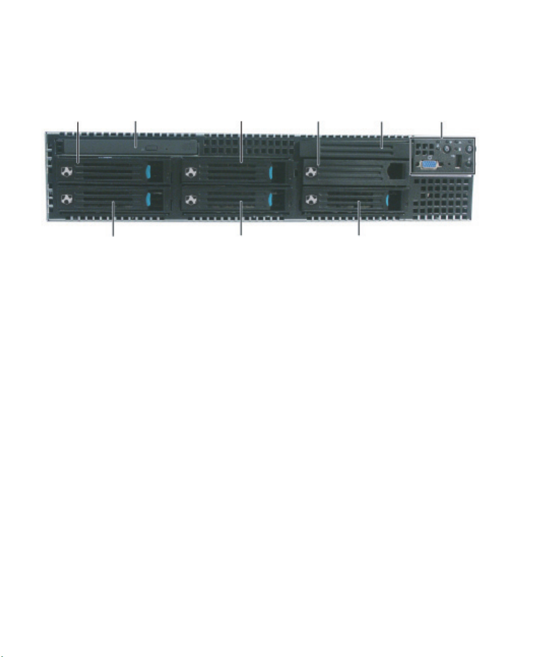
Front
Hard drive bay
(or optional
diskette drive
bay)
Slim-line CD or
DVD drive
Hard drive
bay
Hard drive
bay 6*
Tape drive bay*
(optional kit req’d)
Control panel
(standard)
Hard drive bay
* Optional tape drive installation also requires hard drive bay 6 because of the height of the tape drive.
Hard drive bay
Hard drive bay
2
www.gateway.com
Page 8
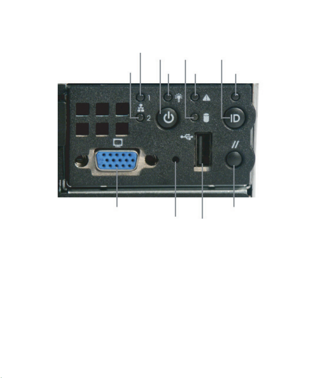
Control panel
LAN 1 activity indicator
LAN 2 activity indicator
Video port
Power
button
Power/
sleep
LED
Non-maskable
interrupt
button
(recessed)
Hard drive
activity
LED
System
status LED
USB port
System ID
button
System ID LED
Reset
button
www.gateway.com
3
Page 9
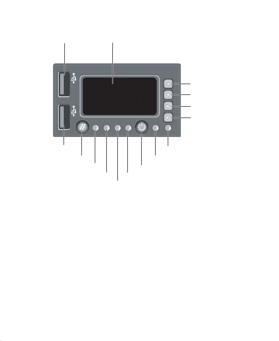
Local Control Panel (LCP) with LCD screen (optional)
USB port
USB port
Reset button
Hard drive activity LED
LAN 1 activity LED
LCD screen
Menu scroll up
Menu scroll down
Menu scroll left
Menu scroll right
System ID LED
Power/sleep LED
Power button
System status LED
LAN 2 activity LED
4
www.gateway.com
Page 10
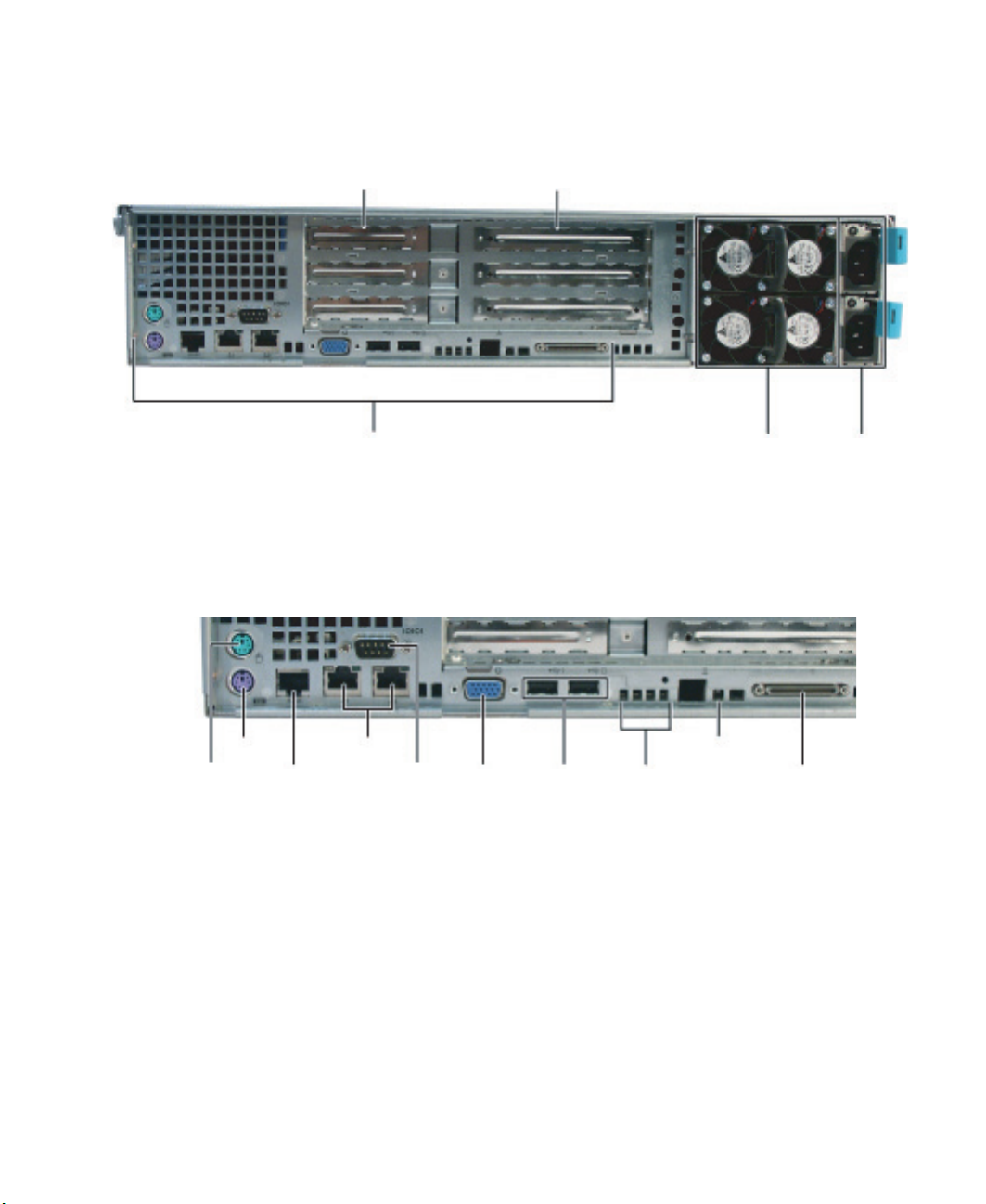
Back
I/O panel
Low-profile PCI
expansion bays
I/O panel
Full-height, full-length
PCI expansion bays
Redundant power
supplies (second
power supply
optional)
Power
connectors
PS/2
mouse
Keyboard
Serial
port B
(RJ-45)
LAN 1
and 2
jacks
Serial
port
Video
port
www.gateway.com
USB
ports
Diagnostic
LEDs
ID LED
External
SCSI
connector
5
Page 11
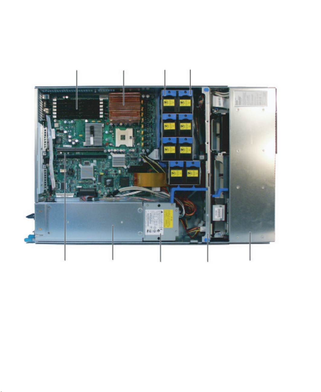
Interior
Memory slots
CPU 1 with
heatsink
Fan modules
(4 standard)
Fan modules
(4 optional)
PCI slots
Power supply cage
6
Power distribution
module
www.gateway.com
SCSI
backplane
Drive bay
area
Page 12
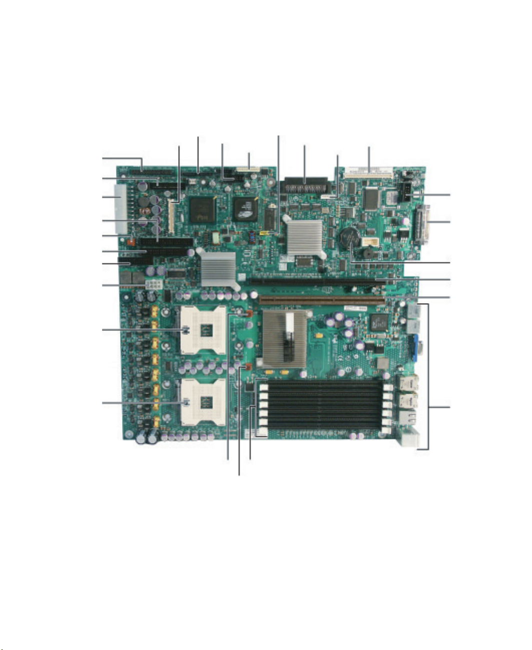
System board
t
Connectors
Control panel
34-pin
Control panel
50-pin
Power
connector
ATA -1 00
connector
System fan
Diskette
System fan
+12V CPU
power
CPU
socket 2
CPU
socket 1
Control panel,
diskette, IDE -
100-pin
SATA
ports
USB
header
IPMB
USB
header
SCSI
channel A
Intel Management
Module (IMM)
connector
ICMB
Serial A
header
SCSI
channel B
Battery
PCI riser slo
(full-height)
PCI riser slot
(low-profile)
I/O panel
CPU 2 fan header
CPU 1 fan header
DIMM sockets
www.gateway.com
7
Page 13
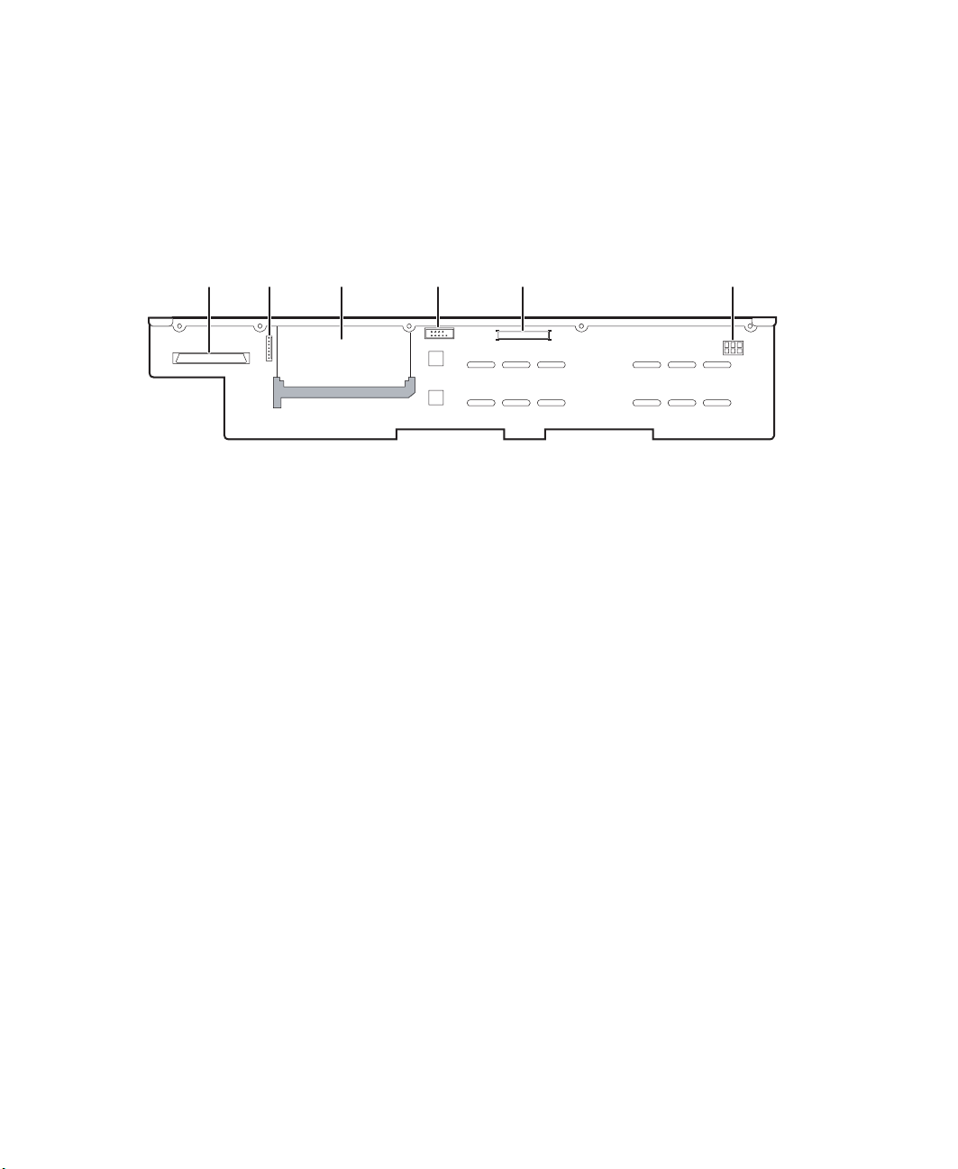
Hot-swap backplane
SCSI backplane
SCSI
channel A
connector
OPT
connector
Opening for
optional
sixth drive
board
Fan
distribution
cable
connector
Flex cable
connector
Backplane
power
connector
8
www.gateway.com
Page 14

Getting Help
In addition to your operating system’s documentation, you can use the following
information resources to help you use your server.
System Companion CD
Use the System Companion CD to access file utilities, Windows 2000 Server drivers, and
documentation for your server and its components. For instructions, see Using Your System
Companion CD.
Gateway Web site
Gateway provides a variety of information on its Web site to help you use your server.
Visit the Gateway Web site at support.gateway.com for:
■ Technical documentation and product guides
■ Technical tips and support
■ Updated hardware drivers
■ Order status
■ Frequently asked questions (FAQs)
Telephone support
You can access a wide range of services through your telephone, including customer service,
technical support, and information services. For more information, see “Telephone
support” on page 122.
www.gateway.com
9
Page 15

10
www.gateway.com
Page 16

Chapter 2
Setting Up Your Server
■ Using your server safely
■ Installing your server into a cabinet
■ Starting and turning off your server
■ Setting up your operating system
11
Page 17

Setting up the hardware
To make sure that your working environment is safe:
■ Use a clean, dry, flat, stable surface for your server. Allow at least 6 inches at the back
of the server for cabling and air circulation.
■ Use the instructions on your server’s setup poster to set up your hardware.
■ Use a grounded (three-prong) surge protector. A surge protector helps protect against
AC power fluctuations. For additional protection from power outages, we recommend
that you use an uninterruptible power supply (UPS).
Caution Your server comes with 3-wire AC power cords fitted with the correct
plug style for your region. If this plug does not match the connector
on your surge protector, UPS, or wall outlet, do not attempt to modify
the plug in any way. Use a surge protector, UPS, or wall outlet that
is appropriate for the supplied AC power cords.
■ Avoid subjecting your server to extreme temperature changes. Do not expose your
server to direct sunlight, heating ducts, or other heat-generating objects. Damage
caused by extreme temperatures is not covered by your warranty. As a general rule,
your server is safest at temperatures that are comfortable for you.
■ Keep your server and magnetic media away from equipment that generates magnetic
fields, such as unshielded stereo speakers. Strong magnetic fields can erase data on
both diskettes and hard drives. Even a telephone placed too close to the server may
cause interference.
12
Important Keep the server boxes and packing material in case you need to ship
the server.
www.gateway.com
Page 18

Protecting from power source problems
Surge protectors, line conditioners, and uninterruptible power supplies can help protect
your server against power source problems.
Surge protectors
During a power surge, the voltage level of electricity coming into your server can increase
to far above normal levels and cause data loss or server damage. Protect your server and
peripheral devices by connecting them to a surge protector, which absorbs voltage surges
and prevents them from reaching your server.
Caution High voltages can enter your server through the power cord, and the
modem and network connections. Protect your server by using a
surge protector. If you have a modem, use a surge protector that has
the appropriate type of modem jack. During an electrical storm,
unplug the surge protector and the modem and network cables.
When you purchase a surge protector:
■ Make sure that the surge protector meets the appropriate product safety certification
for your location, such as Underwriters Laboratories (UL).
■ Check the maximum amount of voltage the protector allows to pass through the line.
The lower the voltage, the better the protection for your server.
■ Check the energy absorption (dissipation) rating. The higher the energy absorption
rating, the better the protection for your server.
Line conditioners
A line conditioner protects your server from the small fluctuations in voltage from an
electrical supply. Most servers can handle this variation, called line noise, without problems.
However, some electrical sources include more line noise than normal. Line noise can also
be a problem if your server is located near, or shares a circuit with, a device that causes
electromagnetic interference, such as a television or a motor.
Some surge protectors and uninterruptible power supplies include simple line-conditioning
capabilities.
Uninterruptible power supplies
Use an uninterruptible power supply (UPS) to protect your server from data loss during a
total power failure. A UPS uses a battery to keep your server running temporarily during
a power failure and lets you save your work and shut down your server. You cannot run
your server for an extended period of time while using only the UPS. To buy a UPS, visit
accessories.gateway.com
.
www.gateway.com
13
Page 19

Mounting your server into a cabinet
The cabinet mounting hardware included with your server should be used with standard
4-post cabinets that have front and back vertical posts. The L-shaped cabinet mounting
brackets can be used for mid-mounting on a 2-post cabinet, but that procedure is not
covered here. If your cabinet is a different type, obtain mounting hardware from the
cabinet manufacturer.
Caution Before attaching cabinet accessories, make sure that the server is
turned off and all power cords are unplugged.
Caution The cabinet must provide sufficient airflow to the front of the server
to maintain correct cooling.
Rackmount kit contents:
■ Server rails (2)
■ Cabinet rails (2)
■ L brackets (2, not used for this type of installation)
■ Fastener pack (1)
14
■ Small screws (4, #6-32 × 3/16-inch)
■ Medium screws (8, #10-32 × ½-inch)
■ Large screws (2, #10-32 × 7/8-inch)
■ Disk guides (2)
■ Handle spacers (2)
■ Nut bars (4)
www.gateway.com
Page 20
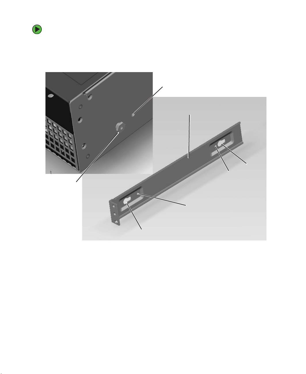
To mount your server in a cabinet:
1 Remove the two screws from each handle, then set the handles and screws aside.
2 Align the slots in a server rail with the studs on the side of the server, then engage
the slots with the studs and slide the rail back until it stops.
Locking screw hole
Server rail
Slot
Locking screw hole
Mounting stud
Locking screw hotel
Slot
3 Align the locking screw holes in the rails with the threaded screw holes in the server,
then install two locking screws through the each rail.
www.gateway.com
15
Page 21
4 Place a disk guide over the disk guide screw hole towards the back of the server.
Disk guide screw hole
5 Install a small screw through the disk guide and tighten the screw. Attach the
remaining disk guide on the other side of the server.
16
Disk guide
Disk guide screw
www.gateway.com
Page 22
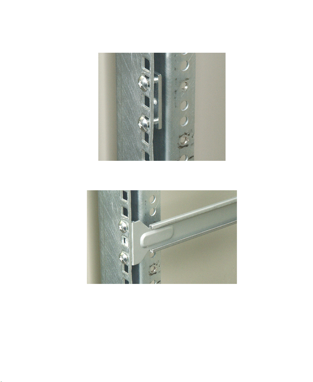
6 Attach a nut bar to the inside of the two back cabinet posts using medium screws,
but do not completely tighten the screws (leave them loose enough to allow insertion
of the cabinet rail in the next step).
7 Insert the slotted foot at the back of each cabinet rail between the nut bar and the
post, then tighten the screws.
www.gateway.com
17
Page 23
8 With the front of the server facing you, lift the server and insert it into the cabinet
from the front, then position the disk guides so they fit in the cabinet rails. The
Gateway 975 server is shown as an example.
Warning Lifting the server and attaching it to the rack is a two-person job. If
needed, use an appropriate lifting device. A fully loaded Gateway
9515 server weighs about 60 lbs. (27.2 kg).
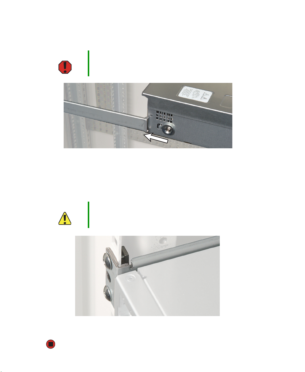
9 Push the server toward the back of the cabinet until the fronts of the server rails touch
the front cabinet posts.
10 Attach one of the server rails to the front cabinet post using two of the medium screws
and one nut bar, then attach the remaining rail to the other cabinet post. The Gateway
955 server shown as an example.
Caution Screws are required to support the front of the server. You must
support the server while installing or removing the front screws and
while sliding the server on or off the cabinet rails.
11 Follow the instructions in “Installing the bezel” on page 19 to attach both handles
and secure the server into the cabinet.
18
www.gateway.com
Page 24
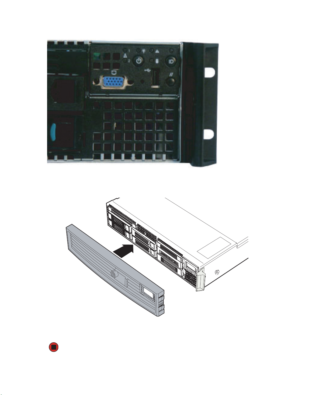
Installing the bezel
Important The bezel is held in place by the server handles. If you are not
installing the bezel, you do not need to install the handles.
To install the bezel (optional):
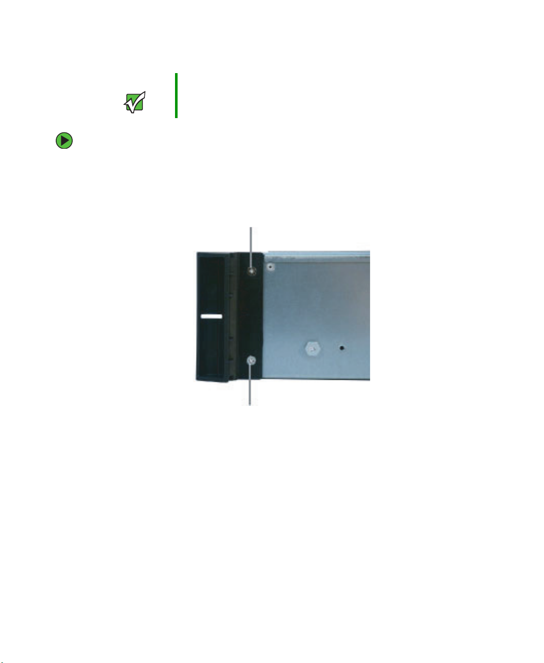
1 With the server pulled out from the cabinet, align the holes in the handle with the
holes in the front sides of the server.
2 Attach the handles to the sides of the server with two mounting screws on each side.
Mounting screw
Mounting screw
3 Push the server, with the handles attached, into the cabinet to determine which holes
in the front posts of the cabinet that the holes in the handles will line up with.
4 Install the mounting nuts (nuts equipped with spring clips that come with most server
cabinets) into the holes in the front posts of the cabinet.
5 Push the server into the cabinet again.
www.gateway.com
19
Page 25
6 Use two screws through each handle to secure the server to the cabinet posts.
Mounting hole
Mounting hole
7 Remove the bezel lock keys from the inside of the bezel, then snap on the bezel with
the control panel area at the top right.
8 To lock the bezel, insert the key into the lock and rotate it ¼ turn clockwise. To unlock
it, rotate the key ¼ turn counter-clockwise.
20
www.gateway.com
Page 26

Removing the server from a cabinet
To remove the server from a cabinet:
Caution Screws are required to support the front of the server. You must
support the server while removing the front screws and while sliding
the server off the cabinet rails.
1 Remove the screws through the handles that hold the server in the cabinet.
2 While supporting the server, slide the server out from the cabinet until it stops.
3 Press the slide release latches on both sides of the server, then pull the server the rest
of the way out of the cabinet.
www.gateway.com
21
Page 27
Starting your server
Before you start your server for the first time:
■ Make sure that the server and monitor are plugged into a power outlet or surge
protector and that the surge protector (if you are using one) is turned on.
■ Make sure that all cables are connected securely to the correct ports and jacks on the
back of the server.
Caution When you connect peripheral devices to the server, make sure that
your server and devices are turned off and the power cords are
unplugged.
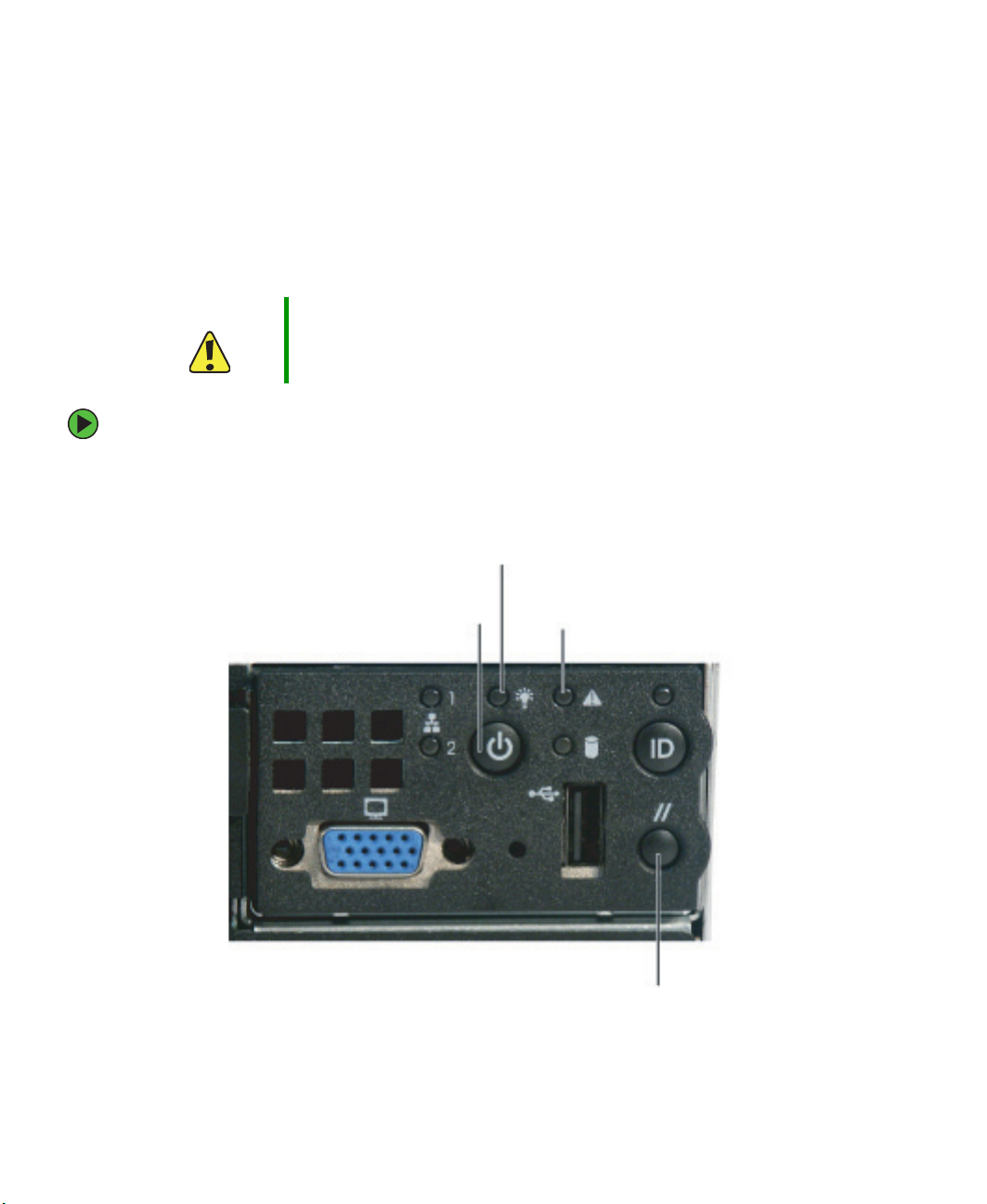
To start the server:
1 Turn on any peripheral devices connected to the server.
2 Press the power button.
Power/sleep LED
Power button
System fault
LED
Reset
button
22
www.gateway.com
Page 28

When the
It means...
power/sleep LED is...
Green (steady on) The server is turned on.
Green (blinking) The server is in sleep mode.
Off The server is turned off.
When the system
It means...
fault LED is...
Green (steady on) The server is operating normally.
Green (blinking) The server is operating in a degraded condition.
Orange (steady on) The server is in a critical or unrecoverable condition.
Orange (blinking) The server is in a noncritical condition.
Off POST failure or full system stop.
If nothing happens when you press the power button:
■ Make sure that the power cable is plugged in securely and that your surge protector
(if you are using one) is plugged in and turned on.
■ Make sure that the monitor is connected to the server, plugged into the power
outlet or surge protector, and turned on. You may also need to adjust the monitor’s
brightness and contrast controls.
■ If you cannot find the cause of the power loss, contact Gateway Customer Care.
For more information, see “Getting Help” on page 9.
3 The first time you turn on the server, any pre-installed operating system may begin
asking you for configuration settings. See your operating system’s documentation for
instructions on configuring advanced settings for your specific network.
Understanding the power-on self-test
When you turn on your server, the power-on self-test (POST) routine checks the server
memory and components. If POST finds any problems, the server displays error messages.
Write down any error messages that you see, then see “Error messages” on page 125 and
“Beep codes” on page 128 for troubleshooting information.
www.gateway.com
23
Page 29

Turning off your server
Every time you turn off your server, first shut down the operating system. You may lose
data if you do not follow the correct procedure.
To turn off the server:
1 See the operating system’s documentation or online help for instructions on shutting
down the operating system. Whenever possible, you should use the operating system’s
shut down procedure instead of pressing the power button.
Caution The power button on the server does not turn off server AC power.
To remove AC power from the server, you must unplug the AC power
cords from the wall outlet or power source. The power cords are
considered the disconnect device to the main (AC) power.
2 If your server did not turn off automatically, press the power button.
- OR -
Press the reset button to reset the server.
24
www.gateway.com
Page 30
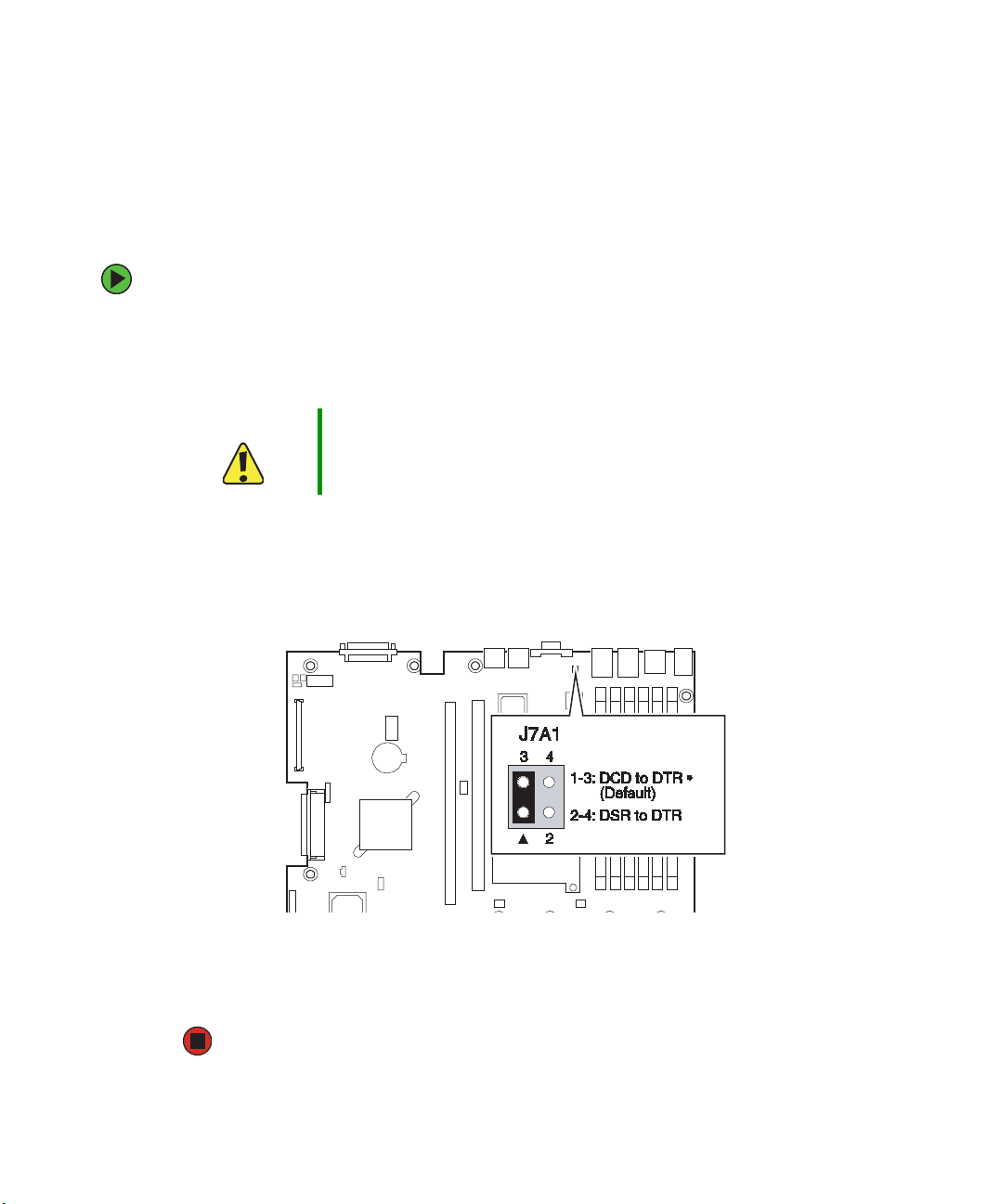
Configuring the RJ-45 serial port
The RJ-45 serial port connector can be configured to support either a Data Set Ready (DSR),
or a Data Carrier Detect (DCD) signal. The default configuration for your server supports
DSR signals. To change the configuration from DSR to DCD signal support, a jumper (J7A1)
must be changed on the system board.
To change the RJ-45 serial port configuration to DCD signal support:
1 Turn off the server, then disconnect the power cords and all other cables connected
to the server.
2 Follow the instructions in “Opening the server case” on page 44.
Caution Moving the jumper while the power is on can damage your server.
Always turn off the server and unplug the power cords and all other
cables before changing the jumper.
3 Remove the PCI riser assembly by following the instructions in “Removing and
installing the PCI riser assembly” on page 79.
4 Remove the jumper across pins 1-3 of jumper J7A1, then place the jumper across
pins 2-4.
5 Reinstall the PCI riser assembly by following the instructions in “Removing and
installing the PCI riser assembly” on page 79.
6 Follow the instructions in “Closing the server case” on page 46.
www.gateway.com
25
Page 31

Setting up the operating system
If you ordered your server with the operating system already installed by Gateway, in most
cases it is completely installed and the basic settings are already configured. The Windows
Small Business Server operating system may require additional installation, depending on
the version you ordered. See your operating system’s documentation for instructions on
completing the installation or configuring advanced settings for your specific network.
If you are installing an operating system because it was not already installed by Gateway,
see the appropriate installation guide for instructions.
Initial hardware settings
Your server comes from the manufacturer with the correct initial hardware settings to
operate your server as configured. However, at some point you might want to change
settings to reflect a tasking change, a change in security requirements, or the addition of
new resources to your server.
General hardware settings, as well as enabling or disabling the onboard LSI RAID solution,
can be changed by using the BIOS Setup utility. The RAID solution can be configured by
using the RAID BIOS console (or the specific RAID console which accompanied a
customized, add-in RAID solution).
For information on the BIOS Setup utility, see “Using the BIOS Setup Utility” on page 111.
For information on BIOS settings, see “BIOS Settings” on page 155. For information on
the RAID BIOS console utility, see “Installing a tape drive” on page 66. For information
on a specific RAID console for an add-in RAID solution, see the documentation on that
hardware which came with your server.
26
www.gateway.com
Page 32

Chapter 3
Maintaining Your Server
■ Caring for your server
■ Recording the BIOS configuration
■ Managing your server and network
27
Page 33

Caring for your server
To extend the life of your server:
■ Be careful not to bump or drop your server.
■ When transporting your server, we recommend that you put it in the original
packaging materials.
■ Keep your server and magnetic media away from equipment that generates magnetic
fields, such as unshielded speakers.
■ Avoid subjecting your server to extreme temperatures. Do not expose your server to
heating ducts or other heat-generating objects. Damage caused by extreme
temperatures is not covered by your warranty. As a general rule, your server is safest
at temperatures that are comfortable for you.
■ Keep all liquids away from your server. When spilled onto server components, almost
any liquid can result in extremely expensive repairs that are not covered under your
warranty.
■ Avoid dusty or dirty work environments. Dust and dirt can clog the internal
mechanisms and can cause the server to overheat.
Cleaning your server
Keeping your server clean and the vents free from dust helps keep your server performing
at its best. Your server cleaning kit could include:
■ A soft, lint-free cloth
■ Glass cleaner
■ An aerosol can of air with a narrow, straw-like extension
■ Isopropyl alcohol
■ Cotton swabs
■ A tape drive cleaning cartridge (if a tape drive is installed)
■ A CD drive cleaning kit
Cleaning tips
■ Always turn off your server and other peripheral devices before cleaning any
components.
Warning When you shut down your server, the power turns off, but some
electrical current still flows through your server. To avoid possible
injury from electrical shock, unplug the power cord and all other
cables connected to the server.
28
www.gateway.com
Page 34

■ Use a damp, lint-free cloth to clean your server and other parts of your server system.
Do not use abrasive or solvent cleaners because they can damage the finish on
components.
■ Keep the cooling vents free of dust. With your server turned off and unplugged, brush
the dust away from the vents with a damp cloth, but be careful not to drip any water
into the vents.
Cleaning the keyboard
You should clean the keyboard occasionally by using an aerosol can of air with a narrow,
straw-like extension to remove dust and lint trapped under the keys.
If you spill liquid on the keyboard, turn off your server and turn the keyboard upside down
to let the liquid drain. Let the keyboard dry completely before trying to use it again. If
the keyboard does not work after it dries, you may need to replace it. Keyboard damage
resulting from spilled liquids is not covered by your warranty.
Cleaning the screen
If your computer screen is a flat panel display, use only a damp, soft cloth to clean it.
Never spray water directly onto the screen.
Caution The computer screen is made of specially coated glass and can be
scratched or damaged by abrasive or ammonia-based glass cleaners.
- OR -
If your computer screen is not a flat panel display, use a soft cloth dampened with glass
cleaner to clean the screen. Never spray cleaner directly onto the screen.
Cleaning the tape drive
If you use a tape drive to back up your files, regular maintenance will lengthen the life
of the drive. To maintain the drive’s reliability:
■ Clean the drive monthly with the cleaning cartridge included with the drive.
■ Remove the tape from the drive whenever the drive is not in use.
www.gateway.com
29
Page 35

Preparing for system recovery
If your system files are corrupted, you may not be able to start the server from the hard
drive. Startup diskettes are diskettes that let you start the server and attempt to fix the
problem. See your operating system’s documentation or online help for instructions on
creating startup diskettes.
Some operating systems also let you create an emergency repair diskette to back up critical
operating system files. See your operating system’s documentation or online help for
instructions on creating and using an emergency repair diskette.
Recording the BIOS configuration
To help keep track of your custom changes to BIOS settings and to prepare for system
recovery, you should record your BIOS configuration after you have your server set up and
working.
To record your BIOS configuration:
1 Print the appendix for “BIOS Settings” on page 155.
2 Restart your server, then press F2 when the Gateway logo screen appears during
startup. The BIOS Setup utility opens.
3 Record the BIOS settings on your printout.
30
www.gateway.com
Page 36

System administration
Gateway Server Manager
Gateway Server Manager lets you manage multiple computers on a Windows network from
a single window, then implement commands and policies across the network with a single
action. With Gateway Server Manager, you can run system management tasks which are
triggered by certain events or conditions.
Printed documentation comes with the Gateway Server Manager CD. You can find additional
documentation in the program’s online help.
Server security
Locking the server
To lock the server:
1 Remove the bezel lock keys from the inside of the bezel, then snap on the bezel. The
handles must be installed for the bezel to snap on. For instructions, see “Installing
the bezel” on page 19.
2 Insert the key into the lock and rotate it ¼ turn clockwise. To unlock it, rotate the
key ¼ turn counter-clockwise.
Using BIOS security passwords
To prevent unauthorized use of the server, you can set server startup passwords. Set up
an administrator password to prevent unauthorized access to the BIOS Setup utility.
To set the BIOS security passwords:
1 Restart your server, then press F2 when the Gateway logo screen appears during
startup. The BIOS Setup utility opens.
2 Select the Security menu.
3 Select Administrator Password.
4 Type the password and press ENTER, then type it again and press ENTER.
5 Save your changes and close the BIOS Setup utility.
www.gateway.com
31
Page 37

To remove a BIOS security password:
1 Restart your server, then press F2 when the Gateway logo screen appears during
startup. The BIOS Setup utility opens.
2 Select the Security menu, then select the password to remove.
3 Enter the current password, then press ENTER.
4 For the new password, leave the password field blank, then press ENTER. The password
is removed.
Tips & Tricks Passwords can also be cleared using jumpers on the system board.
For instructions, see “Resetting BIOS passwords” on page 118.
Local control panel
This optional feature provides an intelligent front panel for the server and allows the user
to configure the server, monitor system status, and control the server from the panel. The
LCD panel has its own microcontroller and is independent of the operating system. Its
4×20 display provides information directly from the Baseboard Management Controller
(BMC) using the IPMB bus.
Interactions
The local control panel can:
■ Poll the BMC to determine alert conditions
■ Query the BMC for system event log entries
■ Display and control the power state of the server
■ Query the BMC for field replaceable units (FRUs)
■ Read BMC sensors
■ Retrieve BIOS POST progress codes
■ Issue IPMI commands to the BMC
■ Obtain BIOS-specific information from the BMC
In addition to the above, system software can also interact with the LCP to:
■ Write characters to the LCP
■ Read characters from the LCP
32
www.gateway.com
Page 38

■ Read the state of the LCP buttons
■ Control the LCP buttons
■ Change LCP menus
■ Read information from the LCP microcontroller
■ Update the LCP firmware
Navigation
The following table shows the LCP menu options:
Scroll up
Scroll down
Scroll left or to previous
option
Scroll right or to previous
page
Menu Options Description
Configure the
server
Network (LAN channel 1 to 3)
■
IP address (BMC)
■
Netmask
■
Gateway address
■
Enable LAN channel
Inventory
■
CPUs
■
DIMMs
■
Drives
■
Power supplies
■
System fans
Server name View server name
Asset tab information View asset tag
Server GUID View server GUID
www.gateway.com
Configure TCO NIC
View system inventory
33
Page 39

Menu Options Description
Configure the
server (cont’d)
Monitor the
server
BIOS revision View BIOS revision
BMC firmware revision View BMC firmware revision
Local Control Panel firmware revision View LCP firmware revision
HSC firmware revision View HSC firmware revision
HSC2 firmware revision View HSC2 firmware revision
POST progress codes View POST progress codes
Server health (drill down to subsystem(s)
View the health of the system
at fault)
System event log View the system event log
CPU sensors (CPU 1 to n)
■
Presence
■
Over temperature
■
On/off line
Chassis status
View CPU related status
View chassis related status
Intrusion status
Power su pply 1 to n
■
Presence
■
Status
Fan 1 to n
■
Presence
■
Status
■
Speed
HSC 1 to 2
■
Presence
■
Status
34
Temperatures (all available temperature
sensors)
www.gateway.com
View all available temperature
sensor status
Page 40

Menu Options Description
Control the
server
Boot flags (select from available boot
flags)
■
Set the flag — one time reboot
■
Reboot the system
Power control
■
Power on
■
Power off
Reset Power control
IPMI control
■
Power on
■
Power off
IPMI command screen
■
Issue an IPMI command (text or hex)
Set up the server Language selection (display loaded
language files)
Status setup
■
Interval timing (set time to retrieve
status)
■
Subsystem mask (mask off
subsystems)
Configure boot order
Power control
Control the power state by
creating button pushes — as
if performed on the front panel
by the user.
IPMI control
Send the chipset a power
control command. The same
functionality as if done over
LAN or by GSM.
Issue an IPMI command
Select the LCP display
language
Set sensor refresh interval
Password setup
■
Password exists/does not exist
■
Create/change password
Remote access rights
■
View (grant or deny)
■
Write (grant or deny)
■
Buttons (grant or deny)
www.gateway.com
Password setup
Remote access control
35
Page 41

Identifying your server
While you are working on a cabinet that contains several slim servers, it can be difficult
to keep track of which server or servers you are currently working on. The System ID
indicator is a blue LED that you can turn on to help you locate the correct server. For the
System ID indicator to turn on, the server does not need to be turned on, but it does need
to be plugged in.
Important If your server has an Intel IMM module installed, the system ID LED
will turn on or off when the System ID button is pressed. If no IMM
Module is installed, the system ID LED will blink when the System
ID button is pressed.
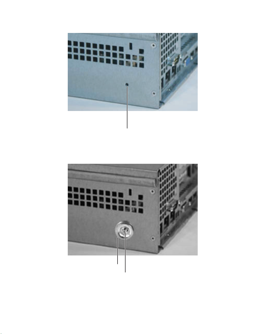
To turn on the System ID indicator:
1 Press the System ID button. The two blue System ID LED indicators turn on.
System ID
indicator
System ID
button
System ID indicator - back
2 To turn off the indicator, press the System ID button.
36
www.gateway.com
Page 42

Updating the baseboard management controller firmware
The baseboard management controller (BMC) performs several system management
functions such as:
■ Monitoring server components (FRU) and sensor data records (SDR) (the information
provided depends on the option selected)
■ Managing non-volatile storage for the system event log and sensor data records
■ Interfacing with the emergency management port to send alerts and interact with
remote management systems.
■ Fault resilient booting (the extent depends on the option selected).
You should update the BMC firmware when Gateway Customer Care has instructed you
to update it. The initial firmware update after installing the IMM Module also requires a
boot block update, but subsequent firmware updates do not.
To update the BMC firmware without Boot Block update:
1 Create a DOS-bootable USB Disk-on-key device or a DOS-bootable CD.
2 Download the BMC update file from support.gateway.com.
3 Follow the instructions included with the update file.
4 Turn off the server, then disconnect the power cord and wait for the Standby power
LED to turn off.
To update the BMC firmware with Boot Block update:
1 Follow the instructions in “Preventing static electricity discharge” on page 43. Make
sure that you disconnect the power cord, and wait until the Standby power LED turns
off.
2 Follow the instructions in “Opening the server case” on page 44.
Caution If you do not disconnect the power cords when instructed to in this
procedure, the BMC firmware will not update.
3 Remove the PCI riser assembly. For instructions, see “Installing and removing PCI
expansion cards” on page 79.
www.gateway.com
37
Page 43

4 Move the shorting block from pins 2-3 to pins 1-2 on the Boot Block Update jumper
(J1B1) on the IMM module.
Important Jumper J1B1 is located on the IMM Module board.
Jumper J1B1 on the IMM
Module board
5 Replace the PCI riser assembly.
6 Follow the instructions in “Closing the server case” on page 46, then reconnect the
power cord.
7 Create a DOS-bootable USB Disk-on-key device or DOS-bootable CD.
8 Download the BMC update file from support.gateway.com.
9 Follow the instructions included with the update file.
10 Turn off the server, then disconnect the power cord and wait for the Standby power
LED to turn off.
11 Follow the instructions in “Opening the server case” on page 44.
38
www.gateway.com
Page 44

12 Remove the PCI riser assembly.
13 Move the shorting block on the Boot Block jumper (J1B1) back to pins 2-3.
14 Replace the PCI riser assembly.
15 Follow the instructions in “Closing the server case” on page 46.
Updating the FRU/SDR
The FRU/SDR must be updated whenever you add additional hardware to your server
that must be monitored by the BMC. This includes adding a redundant power supply
module, adding redundant hot-swap fans, or adding an Intel Management Module
(IMM). The FRU/SDR must also be updated whenever you update the BIOS.
Each time you update the FRU/SDR, we recommend that you check
support.gateway.com
available than the one included on the SCCD, download the newer version and use
it instead of the SCCD in the following procedure.
To update the FRU/SDR:
1 Boot your server to DOS (using a DOS-bootable diskette, CD, or USB disk on key).
for the most current version of the utility. If a newer version is
2 Put the System Companion CD (or a CD with the FRU/SDR utility on it) in the CD
drive.
3 When the menu opens, select the FRU/SDR utility.
4 Select one of the following options:
Update just the SDR repository - Select this option when sensor information needs to
be changed. For example, if the CPU is upgraded to a higher speed or if memory is
replaced.
-OR-
Update the FRUs and the SDR repository (and mBMC TBLs - if the IMM module is not
present) - Select this option if have installed additional hardware. For example, a
redundant power supply or system fans, or additional memory.
5 You will be asked if you have an optional cooling kit installed. Type Y if your system
has redundant fans installed, or N if you system has only the basic fans installed.
6 Exit the utility, remove the System Companion CD, and reboot your server.
www.gateway.com
39
Page 45

Using your System Companion CD
You can use your System Companion CD to:
■ Install hardware drivers
■ Install programs
■ View server documentation
Instructions for using the CD are provided in Using Your System Companion CD.
40
www.gateway.com
Page 46

Chapter 4
Installing Components
■ Opening and closing the server case
■ Installing and replacing major
components
You must open your server case to install
components. If you are not comfortable with
these procedures, get help from a computer
service technician or contact Gateway Customer
Care.
41
Page 47

Preparing to install components
Selecting a place to work
Work on your server in an area that:
■ Is clean (avoid dusty areas)
■ Is a low-static environment (avoid carpeted areas)
■ Has a stable surface on which to set your server
■ Has enough room to place all of your server parts
■ Is near a grounded outlet so you can test your server after installation
■ Is near a telephone (in case you need help from Gateway Customer Care). The
telephone must be directly connected to a telephone jack and cannot be connected
to your server.
Gathering the tools you need
Some tools and supplies that you may need to work on your server are:
■ A notebook to take notes
■ A Phillips screwdriver
■ A small flat-blade screwdriver
■ Small containers to store various types of screws
■ A grounding wrist strap (available at most electronic stores)
Getting Help
If you have questions about performing any of these procedures, contact Gateway
Customer Care. For more information, see “Getting Help” on page 9.
42
www.gateway.com
Page 48
Preventing static electricity discharge
The components inside your server are extremely sensitive to static electricity, also known
as electrostatic discharge (ESD).
Warning To avoid exposure to dangerous electrical voltages and moving parts,
turn off your server and unplug the power cords and modem cable
before opening the server case.
Caution ESD can permanently damage electrostatic discharge-sensitive
components in the server. Prevent ESD damage by following ESD
guidelines every time you open the server case.
Before working with server components, follow these guidelines:
■ Turn off the server, then unplug the power cords and all other cables.
■ Press the power button to drain any residual power from the server.
■ Wear a grounding wrist strap (available at most electronics stores) and attach it to a
bare metal part of the server. You can also touch a bare metal surface on the back of
the server with your finger.
Warning To prevent risk of electric shock, do not insert any object into the vent
holes of the power supply.
■ Avoid static-causing surfaces such as carpeted floors, plastic, and packing foam.
■ Avoid working on the server when your work area is extremely humid.
■ Remove components from their antistatic bags only when you are ready to use them.
Do not lay components on the outside of antistatic bags because only the inside of
the bags provide electrostatic protection.
■ Always hold expansion cards by their edges or their metal mounting brackets. Avoid
touching the edge connectors and components on the cards. Never slide expansion
cards or components over any surface.
www.gateway.com
43
Page 49
Opening the server case
Because the components inside your server are extremely sensitive to static electricity, make
sure that you follow the instructions at the beginning of this chapter to avoid static
electricity damage.
Caution For correct cooling and air flow, always reinstall the top panel before
you turn on the server. Operating the server without the panel in place
will cause the server to overheat.
To open the server:
1 Follow the instructions in “Preventing static electricity discharge” on page 43. Make
sure you turn off the server, then unplug the power cord and all other cables connected
to the server.
Warning This server has two power cords. To disconnect internal AC power,
you must unplug both power cords.
2 If the bezel is installed, unlock it, then pull it off.
3 If the server is mounted in a cabinet, remove the server from the cabinet. For
instructions, see “Removing the server from a cabinet” on page 21.
Caution Screws are required to support the front of the server when using
the standard cabinet rails. You must support the server while
removing the front screws and while sliding the server off the cabinet
rails.
4 Place the server on a stable, non-skid surface.
5 Remove the shipping screw (if installed).
44
www.gateway.com
Page 50
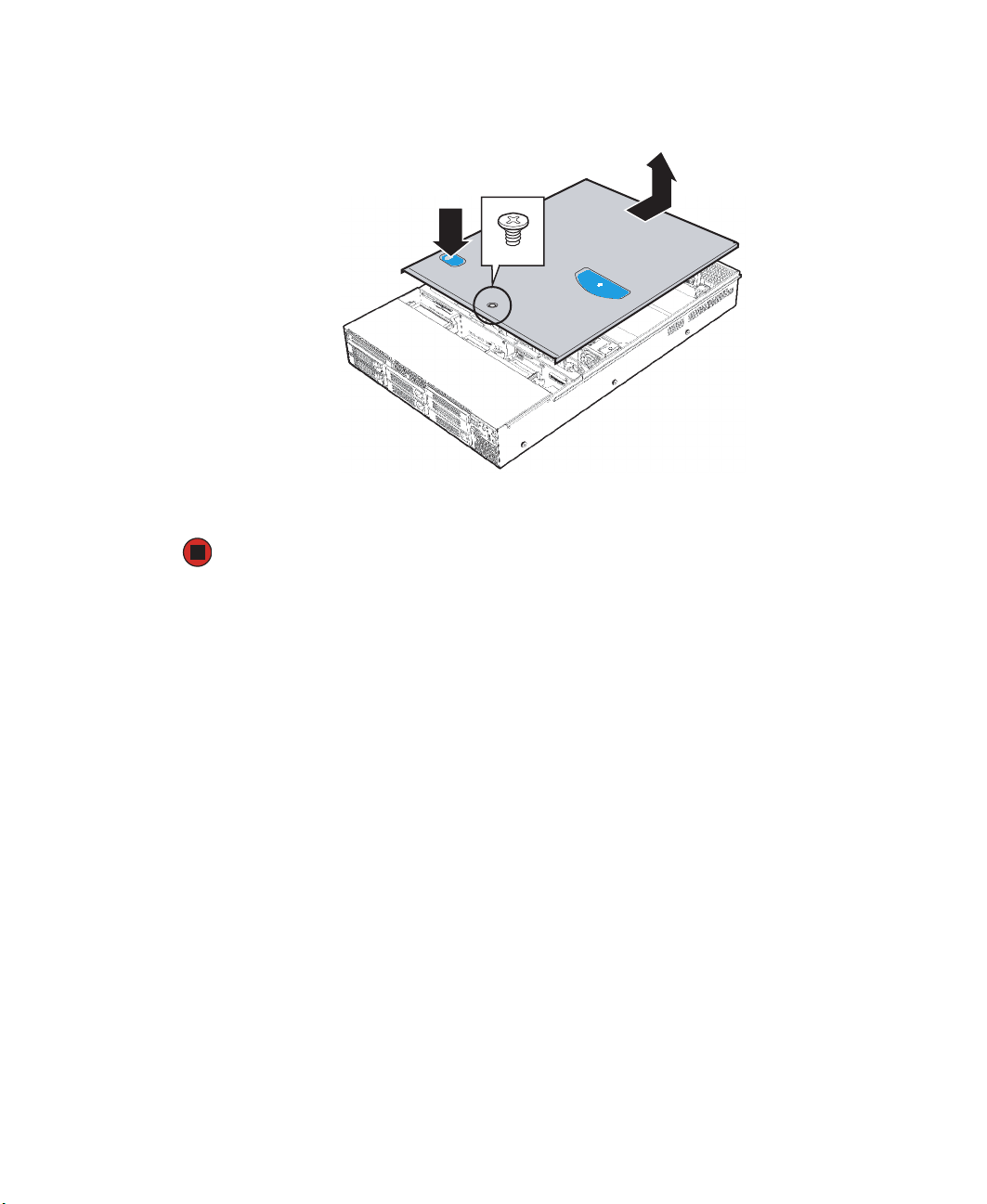
6 Press and hold the panel release button, then slide the top panel toward the back of
the server about 1/2 inch.
Panel
release
button
7 Lift the top panel away from the server.
www.gateway.com
45
Page 51
Closing the server case
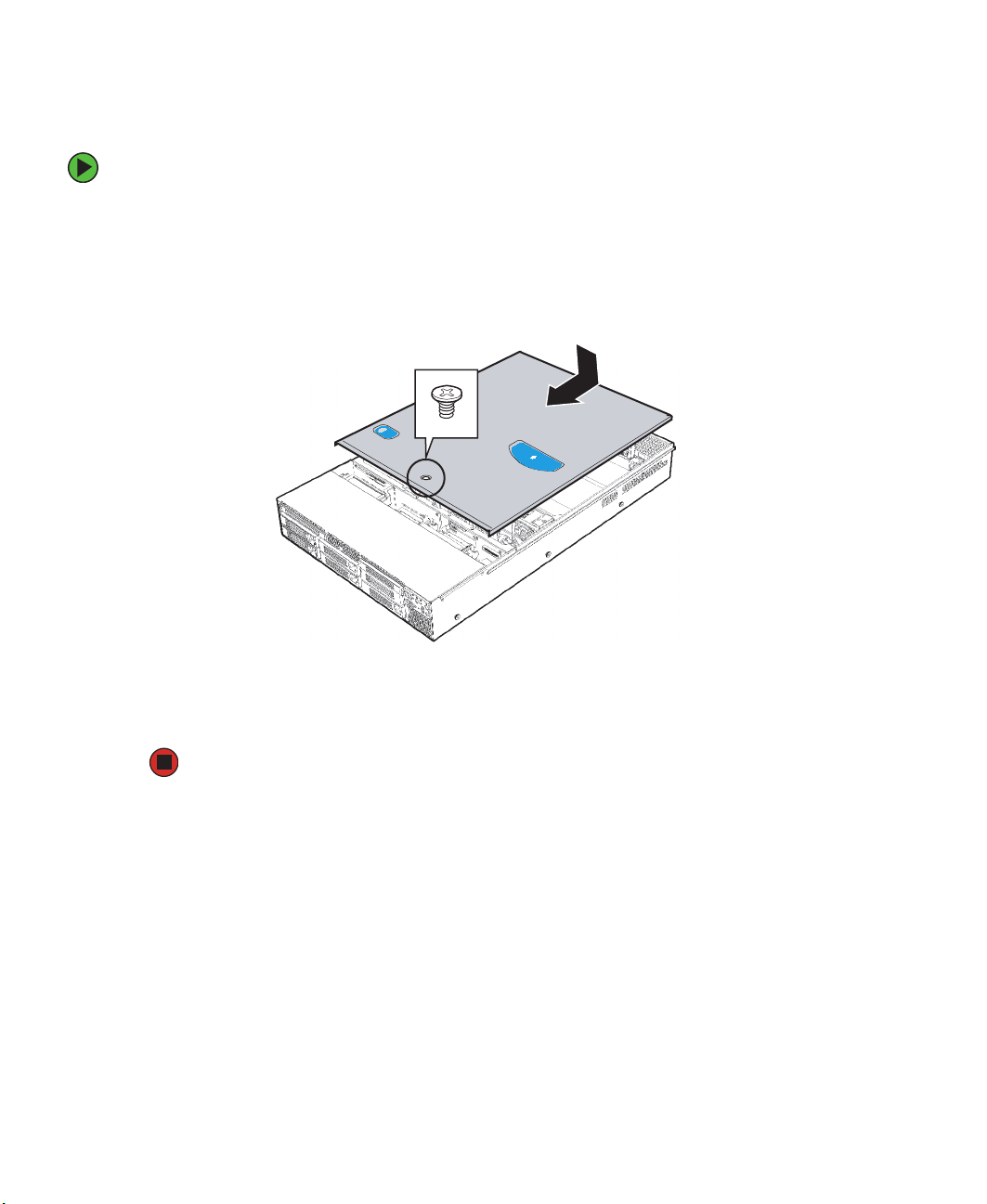
To close the server case:
1 Make sure that all of the internal cables are arranged inside the case so they will not
be pinched when you close the case.
2 Slide the top panel onto the server.
3 Slide the top panel toward the front of the server until it clicks into place.
4 Replace the shipping screw (if necessary).
5 Reconnect the power cords and all other cables.
46
www.gateway.com
Page 52
Removing and installing air ducts, air dams, and baffles
Your server has been engineered to provide correct airflow in the chassis for sufficient
cooling of drives, processors, and power supplies. As your server configuration changes,
the airflow within the chassis will need to be modified to accommodate those changes.
Caution To ensure continued, reliable operation, always operate your server
with the appropriate air ducts, air dams, and baffles in place. Failure
to do this could result in equipment damage.
Removing the processor air duct
The processor air duct normally covers the portion of the system board that includes the
processor(s) and the memory. The air duct will need to be removed if you need to add or
remove a processor or memory in your system, or if you need to replace the system board.
To remove the processor air duct:
1 Follow the instructions in “Preventing static electricity discharge” on page 43. Make
sure you turn off the server, then unplug the power cord and all other cables connected
to the server.
2 Follow the instructions in “Opening the server case” on page 44.
www.gateway.com
47
Page 53

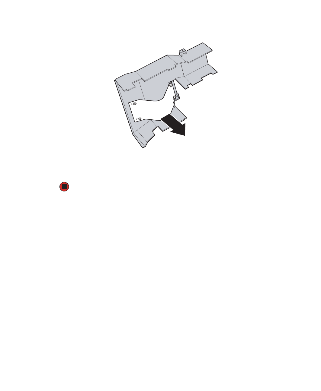
3 Lift the processor air duct from the chassis.
Removing the processor air dam
If you are adding a second processor to a single processor system, you need to remove the
air dam located on the underside of the processor air duct.
Caution If you add a second processor to your server, you must remove the
processor air dam or the processor may overheat, causing possible
data loss and damage to the processor.
To remove the processor air dam:
1 Follow the instructions in “Preventing static electricity discharge” on page 43. Make
sure you turn off the server, then unplug the power cord and all other cables connected
to the server.
2 Follow the instructions in “Opening the server case” on page 44.
3 Follow the instructions in “Removing the processor air duct” on page 47.
48
www.gateway.com
Page 54
4 Turn the processor air duct over, then remove the air dam from the mounting pins.
5 Follow the instructions in “Installing the processor air duct” on page 50.
6 Follow the instructions in “Closing the server case” on page 46.
www.gateway.com
49
Page 55

Installing the processor air duct
To install the processor air duct:
1 Place the processor air duct over the processor sockets. The front edge of the air duct
should contact the fan module, and the top of the installed air duct should be flush
with the top of the power supply.
2 Follow the instructions in “Closing the server case” on page 46.
Removing the air baffles
Your server is equipped with a hot-swap backplane, supporting hot-swap SATA or SCSI hard
drives, so your server has two air baffles.
■ A small air baffle attached to the drive cage area, in front of the hard drive backplane.
■ A large air baffle installed between the power supply and the back of the backplane.
Caution To ensure continued, reliable operation, always operate your server
with the appropriate air ducts, air dams, and baffles in place. Failure
to do this could result in equipment damage.
50
www.gateway.com
Page 56
To remove the air baffles:
1 Follow the instructions in “Preventing static electricity discharge” on page 43. Make
sure you turn off the server, then unplug the power cord and all other cables connected
to the server.
2 Follow the instructions in “Opening the server case” on page 44.
Important Take note of the cable routing under and around the air baffles. You
will need to re-route these cables when the baffles are reinstalled.
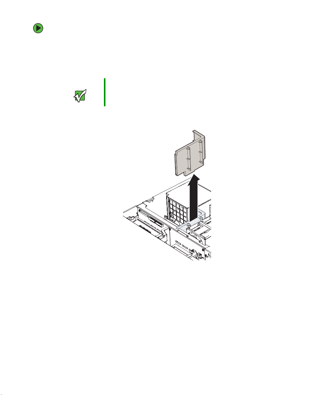
3 Pull up on the large air baffle to remove it from the server chassis.
4 If you are required to remove the small air baffle, go to the next step. If not, go to
Step 5 in “Installing the air baffles” on page 53 when required.
5 Remove the fan module by following the instructions in “Replacing the fan module”
on page 85.
6 Remove the power distribution module by following the instructions in “Replacing
the power distribution module” on page 96.
www.gateway.com
51
Page 57

7 Disengage the hooks that attach the baffle to the back of the drive bay, then pull up
on the small air baffle to remove it from the server chassis.
52
www.gateway.com
Page 58

Installing the air baffles
Caution To ensure continued, reliable operation, always operate your server
with the appropriate air ducts, air dams, and baffles in place. Failure
to do this could result in equipment damage.
To install the air baffles:
1 Place the small air baffle into the chassis behind the drive backplane, routing the cables
as noted in the removal process.
2 Engage the hooks on the baffle with the matching slots on the back of the drive area.
3 Install the hot-swap drive backplane by following the instructions in “Replacing the
hot-swap backplane” on page 100.
4 Install the fan module by following the instructions in “Replacing the fan module”
on page 85.
5 Place the large air baffle into the chassis between the power supply and the hot-swap
drive backplane, routing the cables as noted in the removal process.
www.gateway.com
53
Page 59

6 Line up the hole in the baffle with the guide pin in the chassis, then push down on
the baffle to secure it to the chassis.
Caution Make sure you do not pinch any cables under the baffle as you are
reinstalling it. Failure to do this could result in misalignment of the
baffle and incorrect airflow in the server.
7 Follow the instructions in “Closing the server case” on page 46.
54
www.gateway.com
Page 60

Installing and removing drives
Your server’s basic configuration includes one CD or DVD drive and as many as five SATA
or SCSI hot-swap hard drives. An optional sixth hot-swap hard drive, tape backup drive
(but not both), or diskette drive can also be added.
As you prepare to install drives, remember:
■ If you need to install a diskette drive and a CD or DVD drive is installed in the slim-line
drive bay, you must install the diskette drive in a converted hard drive bay.
■ Before you install a drive, see the drive’s documentation for information on
configuring the drive, setting drive jumpers, and attaching cables.
■ You may need to configure the drives you install using the BIOS Setup utility. Press
F2 at startup to open the BIOS Setup utility.
www.gateway.com
55
Page 61

Installing a diskette in a converted hard drive bay
If you need to install a diskette drive into your server, you must install the diskette drive
in the top, left hard drive bay, directly under the slim-line drive bay.
To install a diskette drive in a converted hard drive bay:
1 Follow the instructions in “Preventing static electricity discharge” on page 43. Make
sure you turn off the server, then unplug the power cord and all other cables connected
to the server.
Caution The diskette drive is not hot-swappable. Before installing or removing
the drive, make sure that power is turned off.
2 Follow the instructions in “Opening the server case” on page 44.
3 Unlock the bezel (if necessary) and remove it by pulling it from the chassis.
4 Remove the upper-left hot-swap hard drive carrier from the server.
5 Remove the rails from the diskette drive conversion kit carrier by removing the four
screws that secure the rails to the carrier.
56
www.gateway.com
Page 62

6 Slide the diskette drive into the drive carrier. The back of the drive should go into
the carrier first with the bottom of the drive facing down.
7 Align the holes in the sides of the diskette drive with the holes in the carrier and
attach the drive to the carrier with the two screws that came with the diskette drive
conversion kit.
8 Reattach the rails to the sides of the carrier with the four screws you previously
removed.
www.gateway.com
57
Page 63

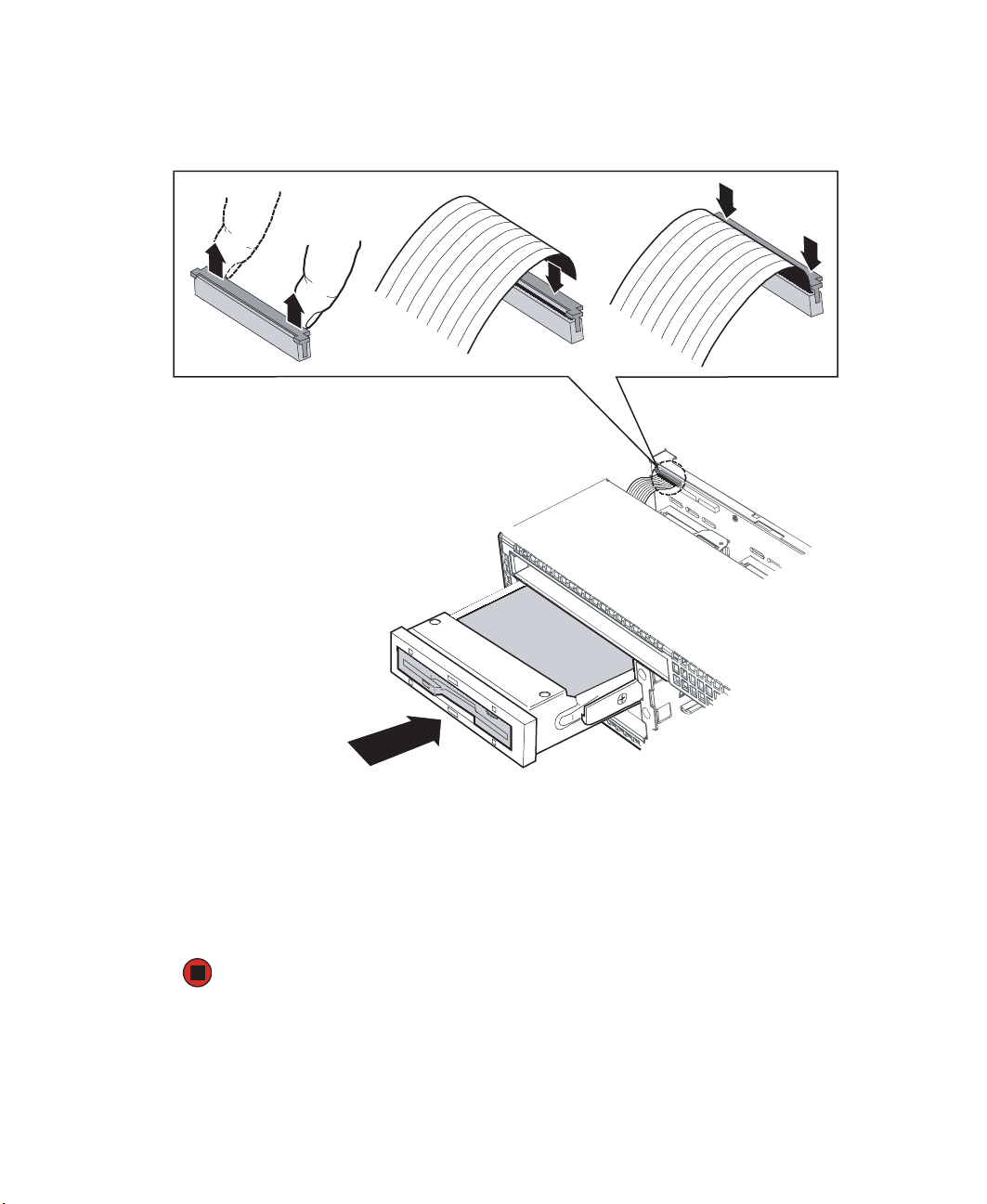
9 Open the connector on the back of the diskette drive by pulling up on the connector
cover.
10 Insert one end of the 26-pin diskette drive flat flex cable into the connector, then
push down on the connector cover to lock it into place.
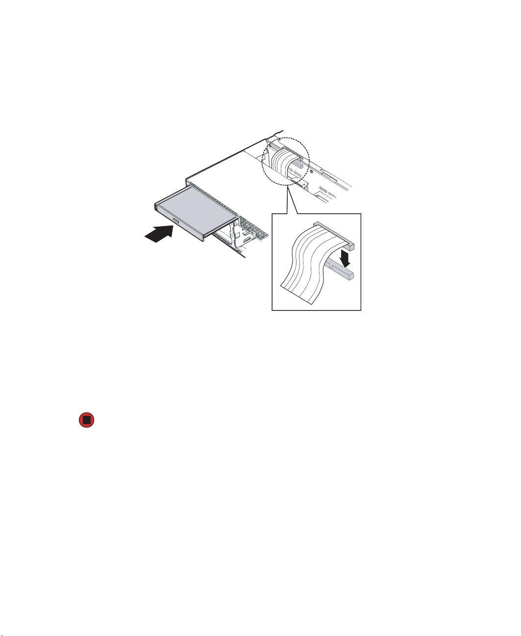
11 Insert the new drive assembly into the upper-left hard drive bay until it clicks into
place.
58
www.gateway.com
Page 64
12 Open the connector labeled “Floppy Con” on the backplane by pulling up on the
connector cover. See “Hot-swap backplane” on page 8 for the location of the
connector.
13 Insert the other end of the diskette flat flex cable into the backplane connector, then
push in on the connector cover to lock the cable into place.
14 Reinstall the bezel, if required, by snapping it into place on the front of the chassis.
15 Follow the instructions in “Closing the server case” on page 46.
16 Reconnect all power cords and peripheral device cables, then turn on the server.
www.gateway.com
59
Page 65

Removing a diskette drive from the converted hard drive bay
To remove a diskette drive from the converted drive bay:
1 Follow the instructions in “Preventing static electricity discharge” on page 43. Make
sure you turn off the server, then unplug the power cord and all other cables connected
to the server.
Caution The diskette drive is not hot-swappable. Before installing or removing
the drive, make sure that power is turned off.
2 Follow the instructions in “Opening the server case” on page 44.
3 Unlock the bezel (if necessary) and remove it by pulling it from the chassis.
4 Pull up on the top of the connector on the backplane marked “Floppy Con” to release
the flat flex cable. See “Hot-swap backplane” on page 8 for the location of the
connector.
5 Push in on the lever at the back of the drive carrier to release the drive carrier from
the drive bay, then slide the diskette drive carrier out through the front of the server.
6 Pull up on the top of the connector on the back of the diskette drive and remove the
flat flex cable.
7 Remove the four screws securing the rails to the carrier, then remove the rails.
8 Remove the two screws securing the diskette drive in the carrier, then slide the drive
out of the carrier.
9 If you are replacing the drive, follow the instructions in “Installing a diskette in a
converted hard drive bay” on page 56.
- OR -
Install an empty hard drive carrier into the empty hard drive bay.
10 Reinstall the bezel, if required, by snapping it into place on the front of the chassis.
11 Follow the instructions in “Closing the server case” on page 46.
12 Reconnect all power cords and peripheral device cables, then turn on the server.
60
www.gateway.com
Page 66

Installing a CD or DVD drive
To install a CD or DVD drive:
1 Follow the instructions in “Preventing static electricity discharge” on page 43. Make
sure you turn off the server, then unplug the power cord and all other cables connected
to the server.
Caution The CD or DVD drive is not hot-swappable. Before installing or
removing the drive, make sure that power is turned off.
2 Follow the instructions in “Opening the server case” on page 44.
3 Unlock the bezel (if necessary) and remove it by pulling it from the chassis.
4 Remove the CD/DVD drive carrier by pressing the blue lever at the back of the carrier
and pushing the carrier out the front of the server.
5 Place the CD or DVD drive in the drive carrier (included with your server) by aligning
the two holes in the left side of the drive with the two alignment pins in the carrier,
then lowering the right side of the drive into the carrier until it clicks into place.
Screws
Drive carrier
www.gateway.com
Interposer board
CD or DVD drive
61
Page 67
6 Align the connector on the interposer board with the connector on the back of the
CD or DVD drive, then attach the board to the drive with two screws (included with
your server).
7 Attach the 44-pin CD drive cable to the back of the interposer board.
8 Slide the CD or DVD drive assembly into the slim-line bay until it clicks into place.
9 Connect the other end of the 44-pin cable into the connector on the backplane. See
“Hot-swap backplane” on page 8 for the location of the connector.
10 Reinstall the bezel, if required, by snapping it into place on the front of the chassis.
11 Follow the instructions in “Closing the server case” on page 46.
12 Reconnect all power cords and peripheral device cables, then turn on the server.
62
www.gateway.com
Page 68

Removing a CD or DVD drive
To remove a CD or DVD drive:
1 Follow the instructions in “Preventing static electricity discharge” on page 43. Make
sure you turn off the server, then unplug the power cord and all other cables connected
to the server.
Caution The CD or DVD drive is not hot-swappable. Before installing or
removing the drive, make sure that power is turned off.
2 Follow the instructions in “Opening the server case” on page 44.
3 Unlock the bezel (if necessary) and remove it by pulling it from the chassis.
4 Disconnect the 44-pin CD drive cable from the backplane. See “Hot-swap backplane”
on page 8 for the location of the connector.
5 Push in on the blue lever at the back of the drive carrier to release the drive carrier
from the drive bay, then slide the drive carrier out through the front of the server.
6 Press down on the side of the drive carrier to release the drive from the carrier.
7 Disconnect the 44-pin CD drive cable from the back of the interposer board.
8 Pull up on the top of the connector on the back of the CD or DVD drive and remove
the flat flex cable.
9 Remove the four screws securing the rails to the carrier, then remove the rails.
10 Remove the two screws securing the interposer board to the back of the CD or DVD
drive, then remove the interposer board.
11 Follow the instructions in “Installing a CD or DVD drive” on page 61.
- OR -
Install a slim-line drive bay filler panel into the empty bay.
12 Reinstall the bezel, if required, by snapping it into place on the front of the chassis.
13 Follow the instructions in “Closing the server case” on page 46.
14 Reconnect all power cords and peripheral device cables, then turn on the server.
www.gateway.com
63
Page 69
Installing a hard drive
Use this procedure to add or replace a hard drive in a hot-swap bay. Your server supports
as many as five 1-inch high 3.5-inch hot-swap SATA or SCSI hard drives (six with optional
sixth drive board). You can purchase additional drives through your Gateway Sales or
Customer Care representative.
Important Gateway tests and verifies the operation and compatibility of the
drives it sells. Especially in a hot-swap or mission-critical
environment, additional or replacement drives must conform to
Gateway standards.
To install a hot-swap hard drive:
1 Unlock the bezel (if necessary) and remove it by pulling it from the chassis.
Caution Before you remove a failed drive, use the appropriate software and
utilities installed on the server to stop all activity on the failed drive.
Instructions for using the software are provided by the software
manufacturer. Failure to do so may destroy the data on the drive.
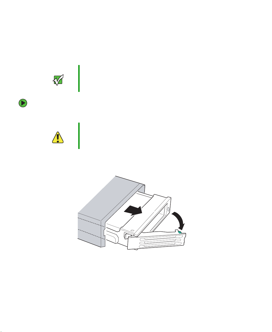
2 Press the green release button on the hot-swap tray lever, then swing the lever open
all the way.
3 Pull the drive carrier straight out of the server.
64
www.gateway.com
Page 70
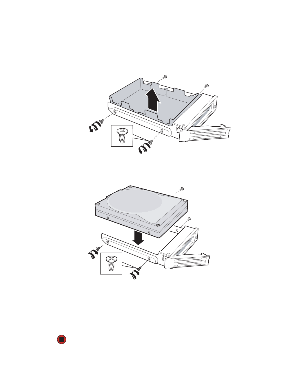
4 If you are replacing a hard drive, remove the four screws that secure the old hard drive
to the drive tray, then remove the drive from the tray.
- OR -
If you are adding a new drive, remove the four screws that secure the hard drive spacer
to the drive tray, then remove the spacer from the tray.
5 Line up the screw holes in the new drive with the holes in the side of the drive tray,
then secure the drive to the tray with the four screws you removed in Step 4.
6 Make sure that the tray’s release lever is open, then slide the new drive into the empty
hot-swap bay.
7 When the drive carrier lever begins to close by itself, push on the lever to lock the
drive assembly into the drive bay.
8 Reinstall the bezel, if required, by snapping it into place on the front of the chassis.
www.gateway.com
65
Page 71

Installing a tape drive
Important Although the power and SCSI cables for the tape drive are not
included with your server, they can be purchased from Gateway.
Important A tape drive can only be installed in your server if a sixth hard drive
(and the sixth drive board) is not already installed. The installed tape
drive will occupy the sixth drive bay and the space above it (covered
initially by the tape drive filler panel).
Tape drive installation requires:
■ A tape drive installation kit
■ A 3.5-inch SCSI tape drive
■ Either a SATA or SCSI backplane already installed in your server
To install a tape drive:
1 Follow the instructions in “Preventing static electricity discharge” on page 43. Make
sure you turn off the server, then unplug the power cord and all other cables connected
to the server.
2 Follow the instructions in “Opening the server case” on page 44.
3 Unlock the bezel (if necessary) and remove it by pulling it from the chassis.
66
www.gateway.com
Page 72

4 Using a long-bladed screwdriver, push the tape drive filler panel out of the front of
the chassis.
5 Remove the blank drive carrier from the sixth hard drive bay by following the
instructions in “Installing a hard drive” on page 64.
6 Secure the tape drive to the tape drive carrier (provided with the optional tape drive
kit) with the four screws that are included in the kit.
www.gateway.com
67
Page 73

7 Slide the tape drive assembly into the tape drive/sixth drive bay until it clicks into
place.
8 Connect the end of the SCSI cable labeled “Tape Drive” to the SCSI connector on the
tape drive.
68
www.gateway.com
Page 74

9 Route the SCSI cable along the front of the fan module, then through the openings
in the underside of the large air baffle. Follow the instructions in “Removing the air
baffles” on page 50 and “Installing the air baffles” on page 53.
10 Attach the end of the SCSI cable labeled “Server Board” to the SCSI connector on your
add-in SCSI card.
11 Connect the 7-pin tape drive power cable to the “OPT CONN” connector on the
hot-swap drive backplane, the connect the 4-pin tape power cable from the backplane
to the tape drive.
12 Reinstall the bezel, if required, by snapping it into place on the front of the chassis.
13 Follow the instructions in “Closing the server case” on page 46.
Installing the SCSI sixth drive option
A sixth SCSI drive may be added to your server by using the SCSI backplane accessory kit.
Once the kit is installed, an additional hot-swap hard drive may be installed in the server
(see “Installing a hard drive” on page 64).
Important You cannot install both the sixth drive option and a tape drive. Due
to size limitations, the tape drive occupies the sixth drive bay and the
space above it.
To install the sixth drive option:
1 Follow the instructions in “Preventing static electricity discharge” on page 43. Make
sure you turn off the server, then unplug the power cord and all other cables connected
to the server.
Caution The diskette drive is not hot-swappable. Before installing or removing
the drive, make sure that power is turned off.
2 Follow the instructions in “Opening the server case” on page 44.
3 Unlock the bezel (if necessary) and remove it by pulling it from the chassis.
4 Remove the filler panel from the sixth drive bay by using a long bladed screwdriver
to push it out the front of the chassis.
5 Remove the fan module by following the instructions in “Replacing the fan module”
on page 85.
www.gateway.com
69
Page 75

6 Hold the sixth drive option board above and in front of the opening in the backplane.
7 Align the tabs in the option board with the holes in the backplane, then move the
board down and toward the back of the chassis to seat the board.
Make sure the bottom of the option board seats into the plastic retainer at the bottom
of the opening in the backplane.
8 Connect the end of the long SCSI cable labeled “Backplane” to the connector on the
sixth drive option board labeled “M/B,” then connect the remaining end of the cable
to the SCSI connector on the system board or SCSI add-in card.
9 Connect one end of the short SCSI cable labeled “Backplane” to the backplane
connector labeled “SCSI CH A,” then connect the other end to the sixth drive option
board SCSI connector on the back of the board.
10 Using the power cable labeled “Drive 5 Pwer” (included with the sixth drive option
kit), connect one end to the “OPT” connector on the sixth drive option board and
the other end to the “OPT END” connector on the backplane. See “Hot-swap
backplane” on page 8 for connector locations.
11 Reinstall the fan module by following the instructions in “Replacing the fan module”
on page 85.
12 Follow the instructions in “Closing the server case” on page 46.
70
www.gateway.com
Page 76

13 Install the SCSI drive into the sixth drive bay by following the instructions in
“Installing a hard drive” on page 64.
14 Reinstall the bezel, if required, by snapping it into place on the front of the chassis.
Configuring your onboard RAID solutions
Your server comes equipped with an onboard, chipset SCSI RAID solution, which supports
RAID levels 0 (striping) and 1 (mirroring). The onboard RAID solutions can be enabled in
the BIOS (page 160) and configured by launching the appropriate RAID BIOS console
during the boot process.
Level Description and use Pros Cons Number
of drives
0 Data divided into blocks and
distributed sequentially (pure
striping). Use for non-critical data
that requires high performance
1 Data duplicated on another disk
(mirroring). Use for
read-intensive, fault-tolerant
systems.
High data
throughput for
large files
100 percent
data
redundancy,
providing fault
tolerance.
No fault tolerance.
Data is lost if a drive
fails.
More disk space
required. Reduces
usable disk space
to the size of the
smallest drive.
Reduced
performance during
rebuilds.
One or
two (this
server
only)
Tw o Ye s
Configuring the onboard SCSI RAID solution
To launch the SCSI RAID BIOS console:
1 Restart your server.
2 Press F2 when the Gateway logo screen appears during startup. The BIOS Setup utility
opens.
3 From the Main BIOS menu, select the Advanced menu.
Fault
Tolerant
No
4 Select the PCI Configuration sub-menu.
5 For the Onboard SCSI option, click Enabled.
6 Exit the BIOS Setup utility.
7 Restart your server.
www.gateway.com
71
Page 77

During the boot process you will see the following message:
Press <Ctrl>-<C> for BIOS Console
8 Press and hold the CTRL key, then press the C key. The RAID BIOS console will open.
9 Configure the RAID options, then exit the RAID BIOS console.
10 Reboot the server.
Integrated Mirroring configuration
The following must be considered when configuring the onboard SCSI RAID solution for
Integrated Mirroring:
■ The BIOS-based CU allows you to create one mirrored volume per Fusion-MPT
controller.
■ The mirrored volume can have two to six disks or two to five disks if an optional hot
spare disk is used.
■ Disks in a mirrored volume must be connected to the same channel of the same
Fusion-MPT controller, and the controller must be in the BIOS boot order.
■ Disks in an IM volume must be non-removable, single-LUN disks that support
512-byte sectors, wide synchronous transfers, Qtag’d I/Os, and a unit serial number.
The disks must support SMART, and they must be minimally compliant with the
SCSI-2 standard.
■ Disks of different size are allowed in mirrored volumes, but the smallest disk
determines the “logical” size of each disk in the volume.
■ The excess space of larger member disks is not used.
To configure the onboard SCSI RAID solution for Integrated Mirroring:
1 Open the BIOS Setup utility as described in the previous procedure.
2 On the Main menu screen, use the arrow keys to select an adapter, then press Enter.
The Adapter Properties screen opens.
3 Use the arrow keys to select RAID Properties, then press Enter. The RAID Properties
screen opens. Continue with Step 4 to configure a two-disk mirrored volume. Proceed
to Step 5 to configure a mirrored volume with three to six disks.
4 To configure a two-disk mirrored volume, with an optional hot spare disk:
72
www.gateway.com
Page 78

a In the RAID Properties screen, use the arrow keys to select the primary disk for the
IM volume (the disk with the data you want to mirror).
b Use the arrow keys to move to the Array Disk column for this disk, then use the
+ and - keys to select
Yes as the value.
c When the Keep Data/Erase Disk message appears, press F3 to keep the data that
is currently on this disk. The value in the
Array Disk column changes to Primary.
d Use the arrow keys to select the secondary (mirrored) disk for the IM volume, then
select
Yes as the value for the Array Disk column.
If partitions are defined on this disk, a message warns you that data on the disk
will be lost when the mirrored volume is created. Press D
data from the disk, or press any other key to deselect the disk. Continue with Step 6.
ELETE to confirm erasing
5 To configure a mirrored volume with three to six disks, or three to five disks with an
optional hot spare disk:
a On the RAID Properties screen, use the arrow keys to select the first disk for the IM
volume.
b Use the arrow keys to move to the Array Disk column for this disk, then use the
+ and - keys to select
Yes as the value.
c When the Keep Data/Erase Disk message appears, press DELETE to erase the disk.
d Use the arrow keys to select the next disk for the IM volume.
e Select Yes as the value for the Array Disk column.
If partitions are defined on this disk, a message warns you that data on the disk
will be lost when the mirrored volume is created.
f Press DELETE to confirm erasing data from the disk, or press any other key to
deselect the disk.
g Repeat the previous step to select as many as four more disks for the IM volume.
(Or select as many as three more disks if you want to configure a hot spare disk
for the volume.)
6 (Optional) Use the arrow keys to select a hot spare disk for the IM volume. Select Yes
as the value for the Hot Spare column.
7 When you have selected all disks for the IM volume, press ESC and select Save changes,
then exit this menu.
then exit this menu
The IM volume exists as soon as you save the changes. The RAID Properties screen
now displays the IM volume properties and status.
(If you do not want to create the IM volume, select Discard changes,
.)
www.gateway.com
73
Page 79

Integrated Striping configuration
The following must be considered when configuring the onboard SCSI RAID solution for
Integrated Striping:
■ The BIOS-based CU allows you to create one Integrated Striped volume per controller.
■ An IS volume can have from two to six disks.
■ Disks in an IS volume must be non-removable, single-LUN disks that support 512-byte
sectors, wide synchronous transfers, Qtag’d I/Os, and a unit serial number. The disks
must support SMART, and they must be minimally compliant with the SCSI-2
standard.
■ Disks in an IS volume must be connected to the same channel of the same controller,
and the controller must be in the BIOS boot order.
■ Disks of different size are allowed in IS volumes, but the smallest disk determines the
“logical” size of each disk in the volume. The excess space of larger member disks is
not used.
■ Usable disk space for each IS member disk is adjusted down to leave room for Meta
data. Usable disk space may be further reduced to maximize the ability to interchange
disks in the same size classification.
■ The supported stripe size is 64 Kbytes.
To configure the onboard SCSI RAID solution for Integrated Striping:
1 Open the BIOS Setup utility as described in the previous procedure.
2 On the Main menu screen, use the arrow keys to select an adapter, then press ENTER.
The Adapter Properties screen opens.
3 Use the arrow keys to select RAID Properties, then press ENTER. The RAID Properties
screen opens.
4 Use the arrow keys to select the first disk for the IS volume, use the arrow keys to
move to the Array Disk column for this disk, then use the + and - keys to select
as the value for this column.
If partitions are defined on the selected disk, a message appears warning you that data
on the disk will be lost when the striped volume is created. You can then deselect
that disk or erase the disk and continue.
5 Repeat the previous step to select as many as five more disks for the striped volume.
If partitions are defined on the selected disks, a message appears warning you that
data on the disk will be lost when the striped volume is created. You can then deselect
that disk or erase the disk and continue.
74
www.gateway.com
Yes
Page 80

6 When you have selected all disks for the IS volume, press ESC and select Save changes,
then exit this menu
then exit this menu
The IS volume exists as soon as you save the changes. The RAID Properties screen now
displays the IS volume properties and status.
. (If you do not want to create the volume, select Discard changes,
.)
Filling empty drive bays
Empty drive bays in the server must be filled by filler panels, empty drive carriers, or empty
drive trays, as appropriate. With the bezel removed, install the appropriate carrier or filler
panel, then replace the bezel by snapping it into place on the front of the server.
www.gateway.com
75
Page 81
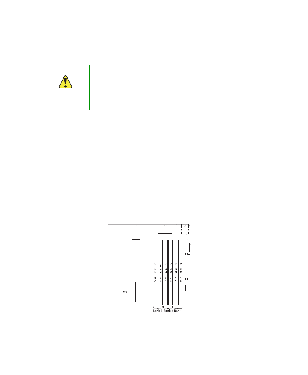
Installing memory
Your server supports from 256 MB to 16 GB* of total memory. Supported DIMM sizes
include 256MB, 512MB, 1GB, 2GB, and 4GB.
Caution Modules must be installed in banks in identical pairs. Use only
DDR2-400 compliant, 240-pin, SDRAM registered ECC, DIMM
memory modules.
Memory modules must be installed in pairs to completely fill each
bank and the banks must be filled in order. If memory is installed
incorrectly, your server will not start.
The BIOS configures the memory controller to run in either single channel or dual channel
mode, depending on the following:
■ If one or more fully populated DIMM banks are detected, the memory controller will
run in dual channel mode.
■ If only a single DIMM is present, the memory controller will run in single channel
mode.
DIMM banks must be populated using the following guidelines:
■ DIMM banks must be populated in order, starting with Bank 1.
■ Dual rank DIMMs must be populated before single rank DIMMs.
■ A maximum of four DIMMs can be populated when all four DIMMs are dual rank
(double row) DIMMs.
* When using Dual Rank (double row) DIMMs, a maximum of four loads per memory
channel is supported. This means a maximum of four dual rank DIMMs can be populated
on this system board.
76
www.gateway.com
Page 82

Supported DDR2-400 DIMM populations
Bank 3 - DIMMs 3A and 3B Bank 2 - DIMMs 2A and 2B Bank 1 - DIMMs 1A and 1B
Single row Single row Single row
Empty Single row Single row
Empty Empty Single row
Empty Double row Double row
Empty Empty Double row
Empty Single row Double row
Single row Single row Double row
Memory online sparing
The chipset on the system board in the Gateway 9515 supports memory online sparing,
which can provide a way to prevent data loss in case of DIMM failure. Memory online
sparing is configured in the BIOS.
Using memory online sparing, one DIMM per channel (selectable in the BIOS setup utility)
is used as a memory spare (the spare DIMM must be equal to, or larger than, the largest
DIMM in that channel). If a DIMM begins to fail, the contents of the failing DIMM is
copied to the spare DIMM in that channel. When all of the data is copied, the primary
DIMM is automatically removed from service. Since one DIMM per channel is always
maintained as a spare, only 75% of the installed memory is usable. For example, if four
2 GB DIMMs and two 4 GB DIMMs are installed, only four are actively used (the other
two are used as spares), so the maximum usable memory is 10 GB.
In case of DIMM failure, a DIMM fault LED adjacent to the DIMM slot will light orange
to indicate the failed memory module.
To install or replace memory:
1 Follow the instructions in “Preventing static electricity discharge” on page 43. Make
sure you turn off the server, then unplug the power cord and all other cables connected
to the server.
2 Follow the instructions in “Opening the server case” on page 44.
www.gateway.com
77
Page 83
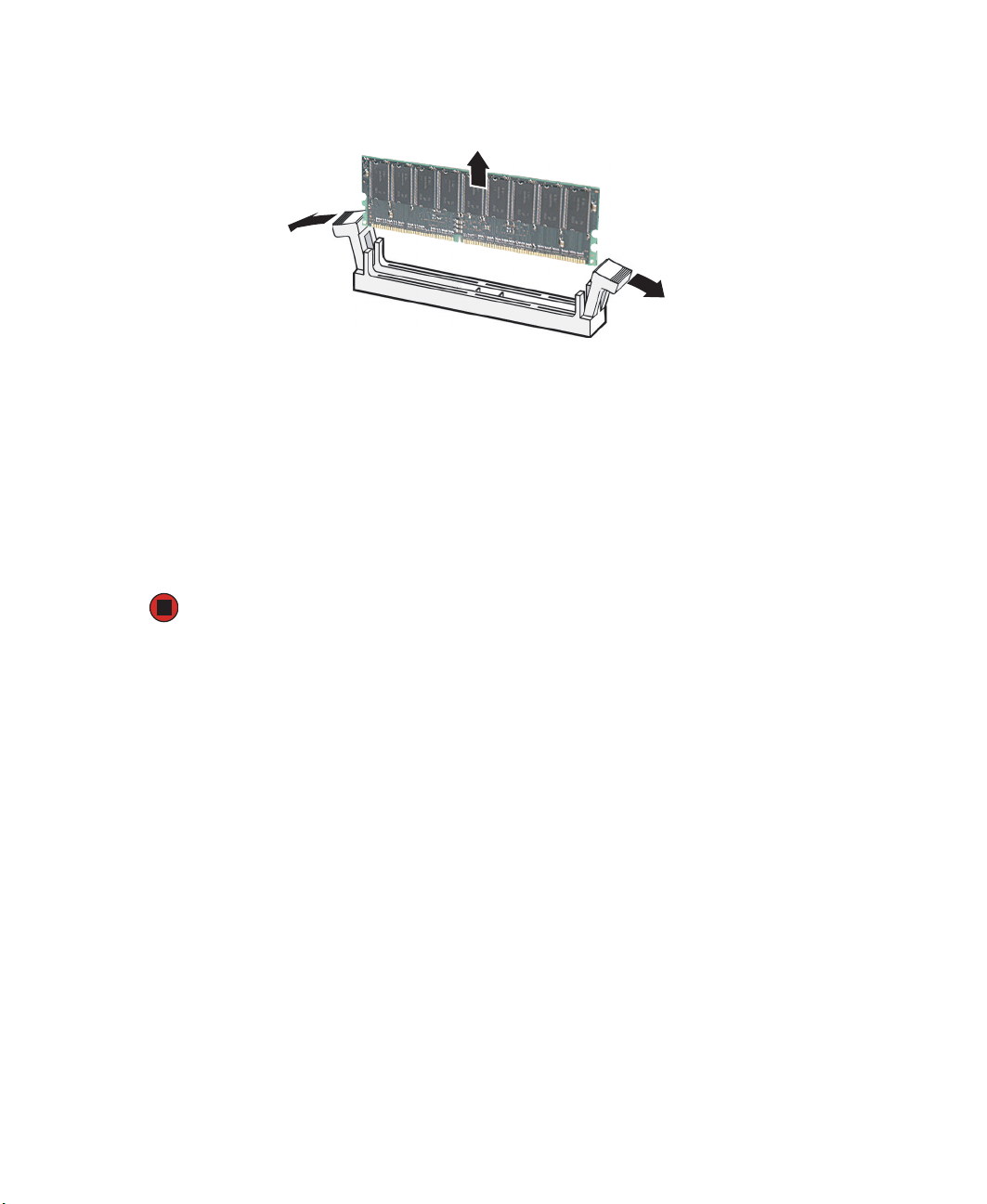
3 Pull the plastic tabs away from the sides of the memory module slot. If you are
replacing a memory module, lift the old module out of the slot.
4 Align the notch on the new module with the notch in the memory module slot and
press the module firmly into the slot. The tabs on the sides of the memory slot should
secure the memory module automatically.
5 Follow the instructions in “Closing the server case” on page 46.
6 Turn on the server and open the BIOS setup utility. Verify the System Memory listed
in the Main menu. When you exit the BIOS setup utility make sure that the operating
system completely loads. If you receive an error, see “Memory” on page 142.
7 Follow the instructions in “Updating the FRU/SDR” on page 39.
78
www.gateway.com
Page 84
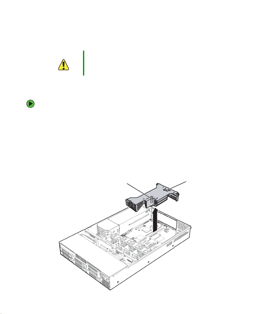
Installing and removing PCI expansion cards
Caution Always operate your server with the PCI riser assembly in place. The
PCI riser assembly is important for correct airflow within the server.
Operating the server without the PCI riser assembly in place could
result in overheating and possible data loss or equipment damage.
Removing and installing the PCI riser assembly
To remove and reinstall the PCI riser assembly:
1 Follow the instructions in “Preventing static electricity discharge” on page 43. Make
sure you turn off the server, then unplug the power cord and all other cables connected
to the server.
2 Follow the instructions in “Opening the server case” on page 44.
3 Follow the instructions in “Removing the processor air duct” on page 47.
4 If you are replacing a card, disconnect any cables that are attached to the old card.
5 Lift up on the two levers on the PCI riser assembly and lift the assembly out of the
chassis.
Lever
www.gateway.com
Lever
79
Page 85
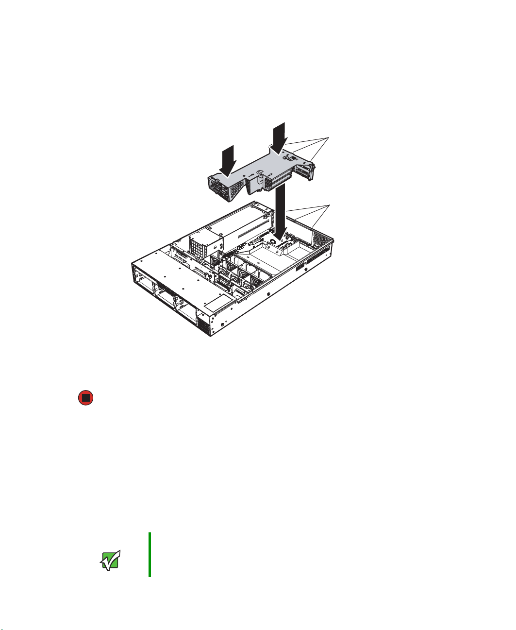
6 Place the PCI riser assembly on a stable, static-free surface and add or remove PCI
expansion cards as necessary.
7 Lower the PCI riser assembly straight down into the server chassis, aligning the hooks
on the back of the riser assembly with the notches in the back of the chassis, then
press firmly to seat the PCI riser assembly into the slots in the system board.
Hooks
Notches
8 Follow the instructions in “Installing the processor air duct” on page 50.
9 Follow the instructions in “Closing the server case” on page 46.
Removing and installing a PCI riser connector
Included with your server were two PCI riser connectors:
■ A full-height PCI-Express riser with two PCI-Express x4 slots
■ A full-height PCI-X riser with one PCI-X slot
PCI riser connectors can be replaced if one fails or if you require a different option.
Important To eliminate the possibility of installing the replacement connectors
on the wrong side of the PCI riser assembly, replace one PCI riser
connector at a time.
80
www.gateway.com
Page 86
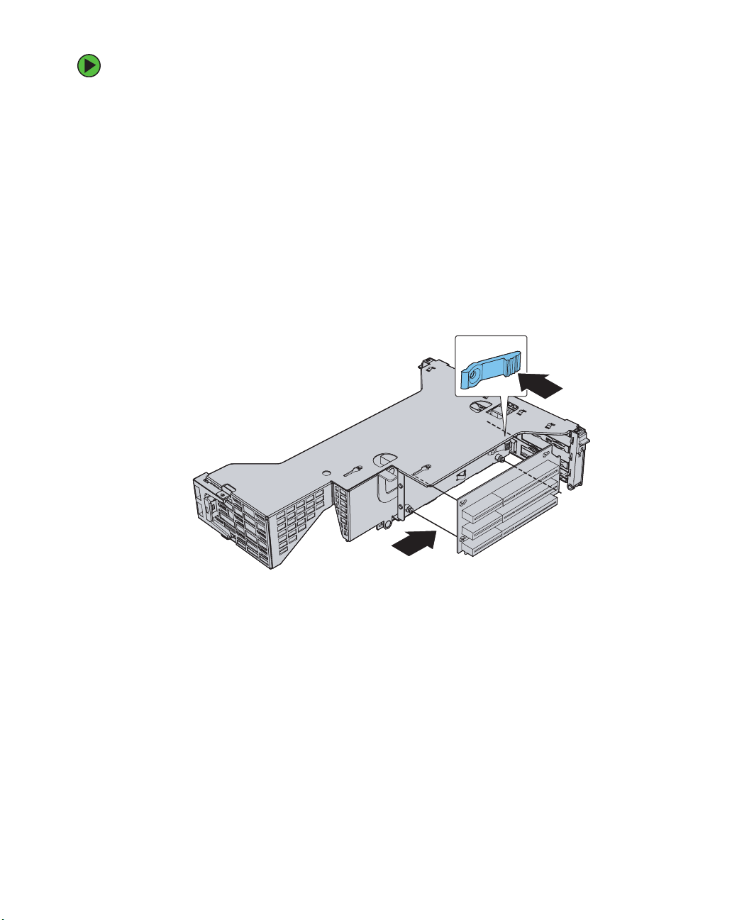
To remove and install a PCI riser connector:
1 Follow the instructions in “Preventing static electricity discharge” on page 43. Make
sure you turn off the server, then unplug the power cord and all other cables connected
to the server.
2 Follow the instructions in “Opening the server case” on page 44.
3 Follow the instructions in “Removing the processor air duct” on page 47.
4 Remove the PCI riser assembly from the server by following the instructions in
“Removing and installing the PCI riser assembly” on page 79.
5 Remove any installed PCI expansion cards by following the instructions in “Removing
a PCI expansion card” on page 82.
6 Push in on the blue release lever at the end of the PCI riser connector.
7 While holding the lever in, push firmly on the front edge of the PCI riser connector,
then slide it to the back to disengage the connector from the riser retention pins.
8 Place the PCI riser connector in a static-free bag to store it for future use.
www.gateway.com
81
Page 87

9 While holding the blue lever in, line up the holes in the replacement PCI riser
connector with the riser retention pins, then place the connector on the retention
pins.
10 Slide the PCI riser connector toward the front of the PCI riser assembly, then release
the blue lever, locking the connector into place.
11 Follow the instructions in “Installing a PCI expansion card” on page 83.
12 Replace the PCI riser assembly by following the instructions in “Removing and
installing the PCI riser assembly” on page 79.
13 Follow the instructions in “Installing the processor air duct” on page 50.
14 Follow the instructions in “Closing the server case” on page 46.
15 See the card’s documentation for software installation instructions.
Removing a PCI expansion card
To remove a PCI expansion card:
1 Follow the instructions in “Preventing static electricity discharge” on page 43. Make
sure you turn off the server, then unplug the power cord and all other cables connected
to the server.
2 Follow the instructions in “Opening the server case” on page 44.
3 Follow the instructions in “Removing the processor air duct” on page 47.
82
www.gateway.com
Page 88

4 Remove the PCI riser assembly from the server by following the instructions in
“Removing and installing the PCI riser assembly” on page 79.
5 Open the PCI retention clip on the PCI riser card assembly.
For full length PCI expansion cards, also open the full length PCI card retention clip
at the front of the PCI riser assembly.
PCI card
retention clip
Full length PCI
card retention
clip
6 Remove the PCI expansion card and place it in a static-free bag for storage.
7 If you are replacing the PCI expansion card, go to “Installing a PCI expansion card”
on page 83.
- OR -
If you are not replacing the PCI expansion card, go to the next step.
8 Install the PCI riser assembly by following the instructions in “Removing and
installing the PCI riser assembly” on page 79.
9 Follow the instructions in “Installing the processor air duct” on page 50.
10 Follow the instructions in “Closing the server case” on page 46.
Installing a PCI expansion card
Important If you are installing a low-profile PCI expansion card, make sure the
card is equipped with a standard, full-height PCI mounting bracket.
www.gateway.com
83
Page 89

To install a PCI expansion card:
1 Follow the instructions in “Preventing static electricity discharge” on page 43. Make
sure you turn off the server, then unplug the power cord and all other cables connected
to the server.
2 Follow the instructions in “Opening the server case” on page 44.
3 Follow the instructions in “Removing the processor air duct” on page 47.
4 Remove the PCI riser assembly from the server by following the instructions in
“Removing and installing the PCI riser assembly” on page 79.
5 Open the PCI retention clip on the PCI riser card assembly.
For full length PCI expansion cards, also open the full length PCI card retention clip
at the front of the PCI riser assembly.
PCI card
retention clip
Full length PCI
card retention clip
6 Remove the EMI filler panel for the card you are installing at the back of the PCI riser
assembly.
7 Insert the PCI expansion card into the card slot, pressing on it with firm, even pressure
until it seats completely. Make sure the bracket inserts into the matching slot.
8 Close the PCI card retention clip(s).
9 Install the PCI riser assembly into the chassis by following the instructions in
“Removing and installing the PCI riser assembly” on page 79.
10 Follow the instructions in “Installing the processor air duct” on page 50.
11 Follow the instructions in “Closing the server case” on page 46.
12 See the card’s documentation for software installation instructions.
84
www.gateway.com
Page 90

Replacing the fan module
To replace the fan module:
1 Follow the instructions in “Preventing static electricity discharge” on page 43. Make
sure you turn off the server, then unplug the power cord and all other cables connected
to the server.
2 Follow the instructions in “Opening the server case” on page 44.
3 Disconnect the fan module cable from the left side of the fan module.
4 Pull up on the release tab on the left side of the fan module to release it from the
chassis, then slide the module to the left until it stops.
5 Lift the fan module from the chassis floor and disconnect the fan distribution cable
from the backplane.
6 Remove the fan module from the chassis.
7 Attach the fan distribution cable from the backplane to the new fan module.
www.gateway.com
85
Page 91
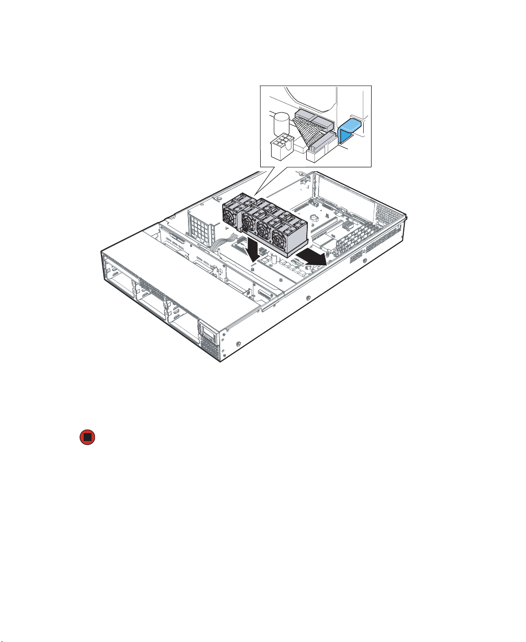
8 Place the fan module over the chassis standoffs and slide the module to the right until
the blue tab clicks into place.
9 Connect the folded fan module ribbon cable to the fan module (and connect the other
end of the cable to the system board, if it is not already connected).
10 Follow the instructions in “Closing the server case” on page 46.
Replacing a system fan
The system fans in this server can be individually replaced. However, there must be at least
four fans installed (in the front four positions) in the fan module for adequate cooling to
take place in the chassis.
The fan module also allows for the installation of four additional, redundant fans, in case
one or more of the primary fans fails. These redundant fans must be installed as a set of
four in the back four positions in the fan module and are installed the same way the
primary fans are installed.
86
www.gateway.com
Page 92

Caution System fans are not hot-swappable. Before removing or replacing a
fan, you must first turn off the server and all peripheral devices
attached to the server, and remove the AC power cord(s) from the
power supply or wall outlet.
To replace a system fan:
1 Follow the instructions in “Preventing static electricity discharge” on page 43. Make
sure you turn off the server, then unplug the power cord and all other cables connected
to the server.
2 Follow the instructions in “Opening the server case” on page 44.
3 Lift the failed fan from the fan module (disregard this step if you are installing
redundant fans).
4 Position the new fan so the connector on the fan is on the bottom right (from the
front of the server).
5 Insert the new fan into the fan module, engaging the connector on the fan into the
matching connector on the fan module.
6 Follow the instructions in “Closing the server case” on page 46.
7 If you added additional, redundant fans, follow the instructions in “Updating the
FRU/SDR” on page 39.
www.gateway.com
87
Page 93

Installing a processor
The server is compatible with Intel® Xeon processors with an 800 MHz front side bus speed
and a processor speed of 2.8 MHz or faster. The server automatically detects the processors
each time you turn on the server. Whenever you install new processors, you should first
install the most current version of the BIOS. For instructions, see “Updating the BIOS” on
page 113.
Warning Processors and heat sinks may be hot if the computer has been
running. Before replacing a processor or heat sink, allow them to cool
for several minutes.
Caution A heat sink must be installed on the processor. Installing a processor
without a heat sink could damage the processor.
Important You must have a processor in the Processor 1 socket, or your server
will not start.
If you are upgrading your server from one processor to two, you may
need to reconfigure your operating system so it can recognize the
additional processor. For instructions, see your operating system’s
documentation.
Important If you install two processors onto the system board, the processors
must be the same speeds, revision, core voltage, and bus speed.
To replace a processor:
1 Install the most current BIOS version. For instructions, see “Updating the BIOS” on
page 113.
2 Follow the instructions in “Preventing static electricity discharge” on page 43. Make
sure you turn off the server, then unplug the power cord and all other cables connected
to the server.
3 Follow the instructions in “Opening the server case” on page 44.
4 Follow the instructions in “Removing the processor air duct” on page 47.
88
www.gateway.com
Page 94

5 Loosen the four captive screws (one on each corner of the heatsink).
6 Remove the heat sink.
Caution The heat sink has Thermal Interface Material (TIM) on the bottom.
Be careful not to damage this material when you remove the heat
sink from the processor. If removing the heat sink also pulls the
processor out of the processor socket, the processor could be
damaged.
If the heatsink sticks to the processor, rotate the heatsink slightly to loosen it.
7 Rotate the processor release lever a full 135° to release the processor, then lift the
processor out of the socket.
www.gateway.com
89
Page 95

8 If you are installing a second processor in your server, follow the instructions in
“Removing the processor air dam” on page 48 to remove the processor air dam in
the processor air duct.
Caution If you add a second processor to your server, you must remove the
processor air dam or the processor may overheat, causing possible
data loss and damage to the processor.
9 Before inserting the processor into the socket, make sure that:
■ The processor release lever is open all the way (135° from the closed position)
■ The triangular arrow on the corner of the processor aligns with the triangular icon
on the corner of the processor socket
10 Install the new processor into the processor socket, then press the processor locking
lever down until it lays flat against the processor socket.
90
www.gateway.com
Page 96
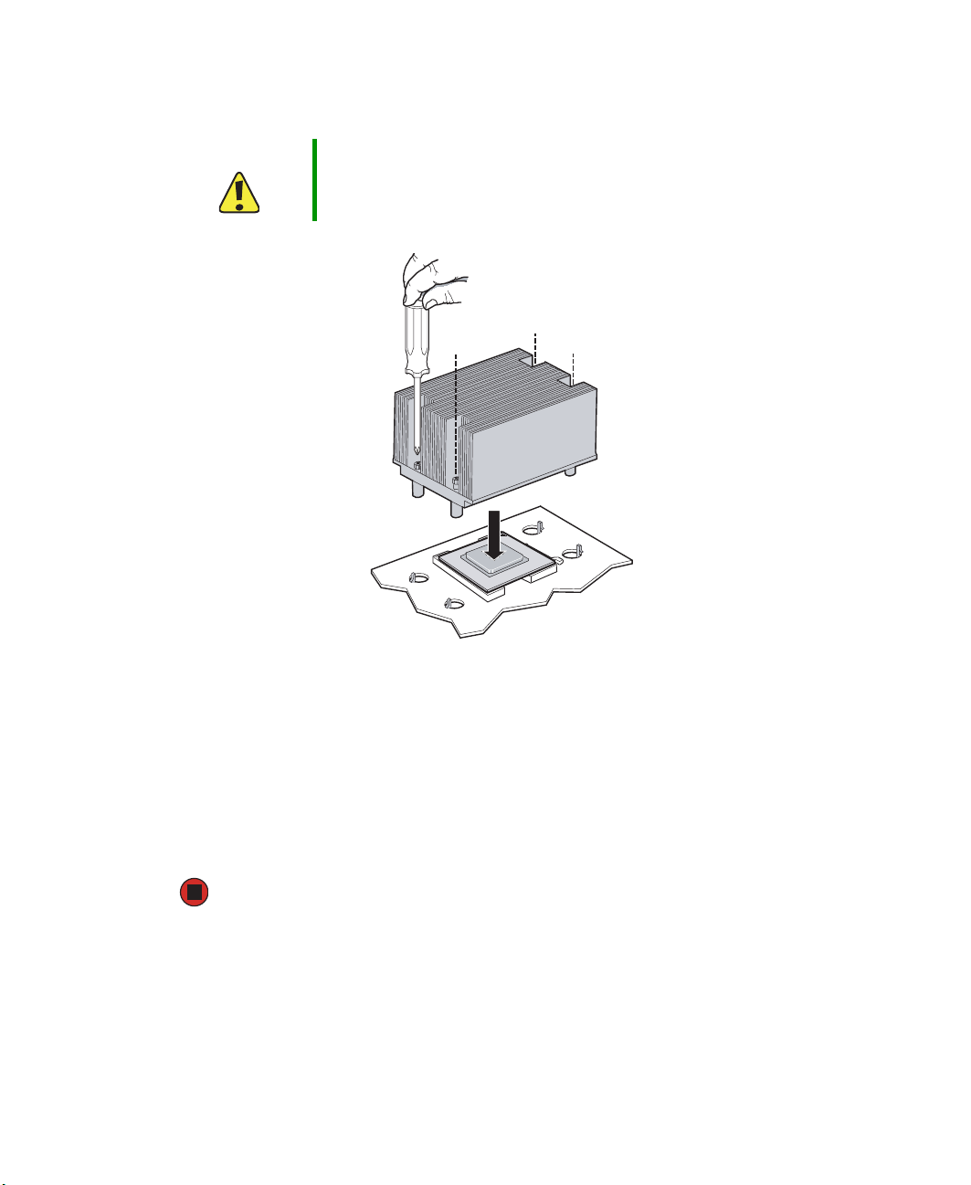
11 Place the heat sink over the processor, lining up the four captive screws with the four
posts surrounding the processor.
Caution The heat sink has Thermal Interface Material (TIM) located on the
bottom of it. Use caution when you unpack the heat sink so you do
not damage the TIM.
12 Loosely screw in the captive screws on the corners of the heat sink, gently tightening
diagonal screws (screw in one screw, then the screw located diagonally to the first
screw). Do not fully tighten one screw before tightening another.
13 Gradually and equally tighten each captive screw until each is firmly tightened. Do
not over-tighten the screws.
14 Follow the instructions in “Installing the processor air duct” on page 50.
15 Follow the instructions in “Closing the server case” on page 46.
www.gateway.com
91
Page 97
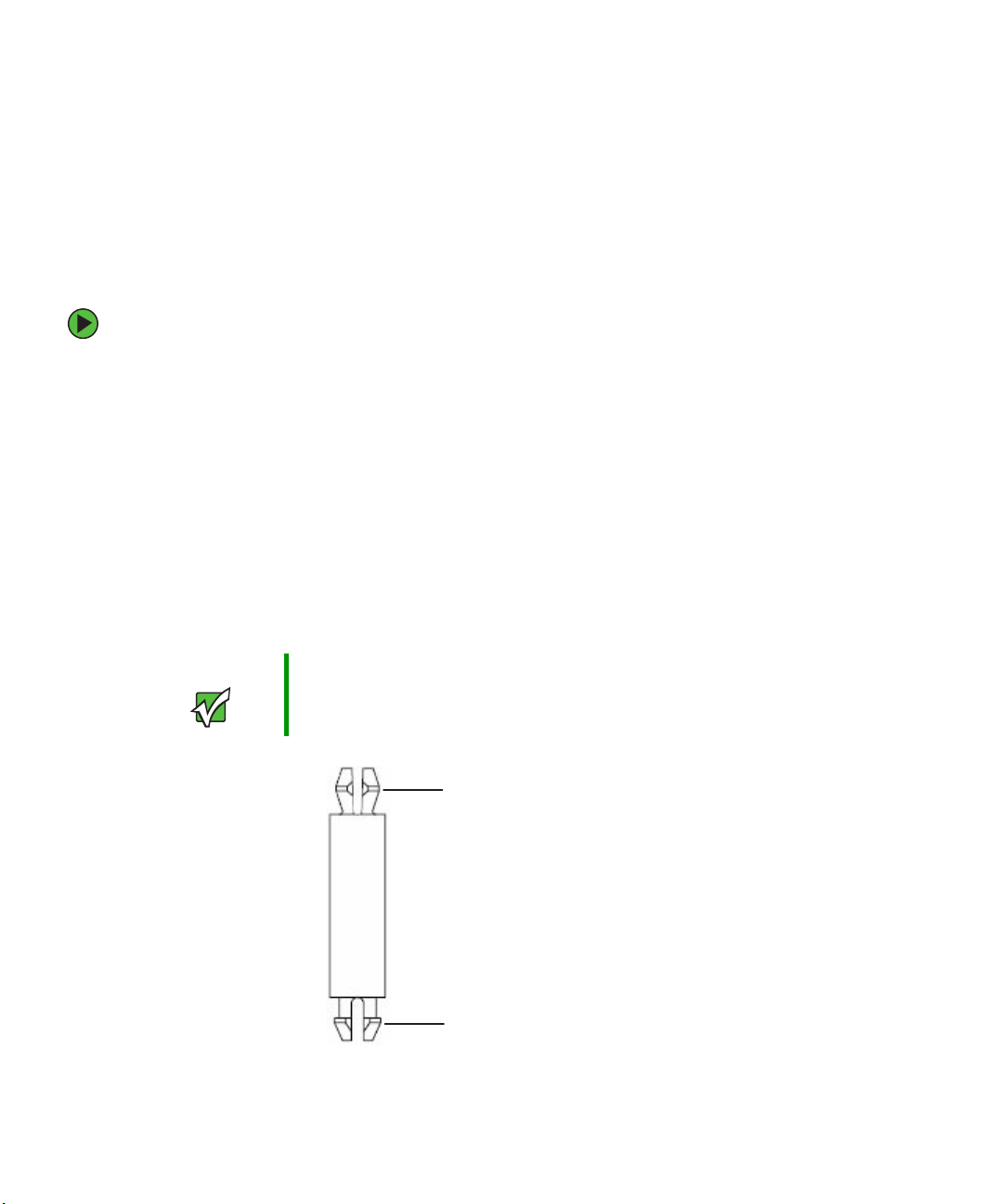
Installing an Intel Management Module (IMM)
The optional Intel Management Module (IMM) provides enhanced levels of server
functionality over the standard baseboard management controller (BMC). Several
additional features become available with the IMM installed, including memory mirroring
and sparing, redundant hot-swap chassis fans, and the local control panel (LCP).
To install an Intel Management Module (IMM):
1 If Gateway Server Manager (GSM) software is installed in your server, uninstall it prior
to installing the IMM module.
2 Follow the instructions in “Preventing static electricity discharge” on page 43. Make
sure you turn off the server, then unplug the power cord and all other cables connected
to the server.
3 Follow the instructions in “Opening the server case” on page 44.
4 Remove the riser assembly by following the instructions in “Removing and installing
the PCI riser assembly” on page 79.
5 Install the nylon standoff into the one corner hole in the IMM module board which
corresponds to one of the holes in the system board (see the illustration on page 93).
92
Important The snap fit ends of the standoff goes into the holes in the IMM
module board. The snap lock ends of the standoff goes into the hole
in the system board.
Snap fit end goes into
IMM board.
Snap lock end goes
into system board.
www.gateway.com
Page 98

6 Find the IMM connector on the left back portion of the system board.
IMM connector
Hole for standoff
7 Grasp the module board by the edges, close to the mounting connector, align the
board with the IMM connector on the system board, then gently apply pressure to
seat the module.
Caution Exercise extreme caution when installing the IMM module. The
module is fragile and can be damaged easily.
Make sure the module is fully seated and the nylon standoff is inserted into the
corresponding hole in the system board.
8 Replace the riser assembly by following the instructions in “Removing and installing
the PCI riser assembly” on page 79.
9 Follow the instructions in “Closing the server case” on page 46.
10 Following the installation of a new IMM module, you must reinstall the GSM software
(supplied on a CD with your server) and update the FRU/SDR (see “Updating the
FRU/SDR” on page 39). When you subsequently reboot your server, the GSM software
will take over management of the server.
www.gateway.com
93
Page 99
Replacing a power supply module
Your server uses as many a s tw o 700 W ho t-swa p p able power supply m odules. If your s e r v e r
has both power supply modules installed, the modules act as redundant, hot-swappable
power supplies. If one of the two power supplies fails, the other power supply supports
the server while you replace the failed power supply. You do not need to turn off the server
or disconnect peripheral devices to replace a failed redundant power supply.
If your server is only equipped with a single power supply, the server must be turned off
and the AC power cord removed before replacing it.
Caution The power supplies in this server contain no user-serviceable parts.
Only a qualified computer technician should service the power
supplies.
Your server comes with 3-wire AC power cords fitted with the correct
plug style for your region. If this plug does not match the connector
on your surge protector, UPS, or wall outlet, do not attempt to modify
the plug in any way. Use a surge protector, UPS, or wall outlet that
is appropriate for the supplied AC power cords.
To replace a power supply module:
1 If your server is equipped with more than one power supply module, determine which
power supply module has failed (the LED on the power supply will be orange).
2 Disconnect the AC power cord from the failed power supply module.
If your server has only one power supply module installed, disconnect the AC power
cord before continuing.
- OR -
If your server has two power supply modules installed, you do not need to turn off
the power to the server before continuing.
94
www.gateway.com
Page 100
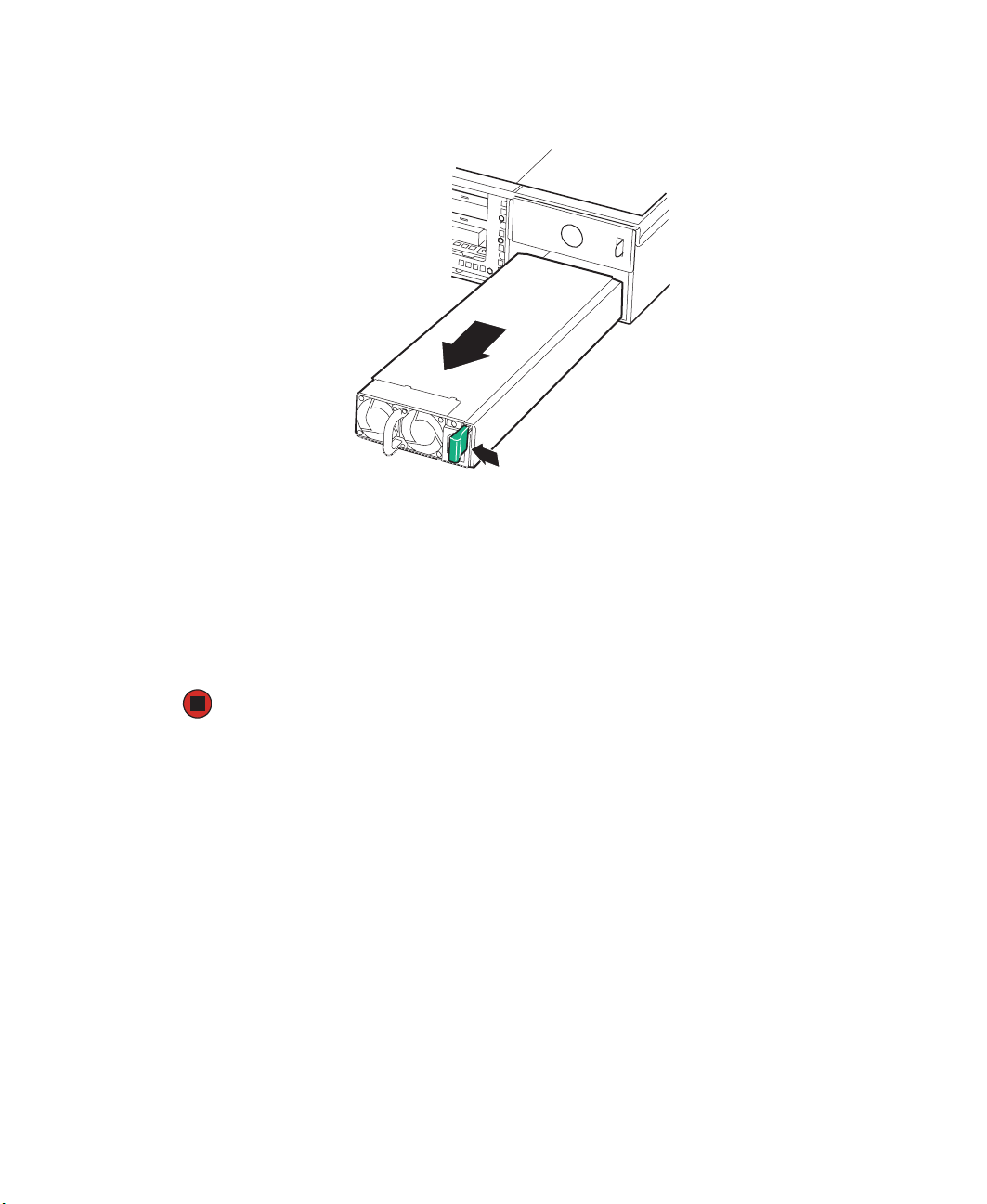
3 Push the power supply’s green locking lever to the left to release the power supply
module from the chassis.
4 Pull the power supply module out of the server.
5 Insert the new power supply module into the server, with the green locking lever to
the right, until it locks into place.
6 Connect the AC power cord to the new power supply module.
7 If you added a redundant power supply module, see “Updating the FRU/SDR” on
page 39.
www.gateway.com
95
 Loading...