


 Loading...
Victoreen 07-494
Wide-Range Digital kVp Meter
Operators Manual
December 2006
Manual No. 168001 Rev. 4
©2006 Fluke Corporation, All rights reserved. Printed in U.S.A.
All product names are trademarks of their respective companies
Fluke Biomedical
Radiation Management Services
6045 Cochran Road Cleveland, Ohio 44139 440.498.2564
www.flukebiomedical.com/rms
|
Table of Contents |
|
Section 1: |
General Information................................................................................... |
1-1 |
1.1 |
Product Description ..................................................................................... |
1-1 |
1.2 |
Specifications............................................................................................... |
1-2 |
Section 2: |
Getting Started........................................................................................... |
2-1 |
2.1 |
Receiving Inspection.................................................................................... |
2-1 |
2.2 |
Storage ........................................................................................................ |
2-1 |
2.3 |
Routine Cleaning ......................................................................................... |
2-1 |
2.4 |
Indicators and Controls................................................................................ |
2-2 |
Section 3: Theory and Applications ........................................................................... |
3-1 |
|
3.1 |
General ........................................................................................................ |
3-1 |
3.2 |
Filtration Effects ........................................................................................... |
3-1 |
3.3 |
Waveform Effects ........................................................................................ |
3-2 |
3.4 |
Focus to Detector Distance (FDD)............................................................... |
3-2 |
3.5 |
mAs Requirements ...................................................................................... |
3-2 |
3.6 |
Detector Positioning..................................................................................... |
3-3 |
3.7 |
Low Battery.................................................................................................. |
3-3 |
3.8 |
Applications ................................................................................................. |
3-3 |
Section 4: |
Operation.................................................................................................... |
4-1 |
4.1 |
Making a Measurement ............................................................................... |
4-1 |
4.2 |
Interpreting Front Panel Warning Indications............................................... |
4-2 |
4.3 |
Viewing the Waveform Output ..................................................................... |
4-3 |
Section 5: Calibration and Adjustments .................................................................... |
5-1 |
|
5.1 |
Low Battery Threshold Adjustment .............................................................. |
5-1 |
5.2 |
End of Shot Adjustment ............................................................................... |
5-3 |
5.3 |
50-90 kVp Calibration .................................................................................. |
5-3 |
5.4 |
80-150 kVp Calibration ................................................................................ |
5-3 |
Section 6: Maintenance and Troubleshooting........................................................... |
6-1 |
|
6.1 |
Battery Replacement ................................................................................... |
6-1 |
6.2 |
Accessing the Circuit Boards ....................................................................... |
6-1 |
6.3 |
Performance Verification (Calibration Constancy) ....................................... |
6-2 |
6.4 |
Verifying Supply Voltages ............................................................................ |
6-3 |
i
(Blank page)

General Information 1
Product Description
Section 1
General Information
1.1 Product Description
The Model 07-494 Wide-Range Digital kVp Meter (Figure 1-1) is a portable, battery operated unit which non-invasively measures the effective peak potential applied to a tungsten target diagnostic x-ray tube. It uses two differentially filtered x-ray detectors whose ratio of integrated outputs is calibrated over the ranges of 50 to 90 kVp and 80 to 150 kVp. The desired range is selected using the range selector on the top of the unit.
Figure 1-1. Model 07-494 Wide-Range Digital kVp Meter
1-1

Victoreen 07-494
Operators Manual
1.2 Specifications
Range |
Low: 50 kVp to 90 kVp |
|
High: 80 kVp to 150 kVp |
|
|
Resolution |
0.1 kVp |
Accuracy |
± 3% or 3 kV, whichever is greater (tungsten target x-ray tube |
|
with 4.5 mm Al total filtration) |
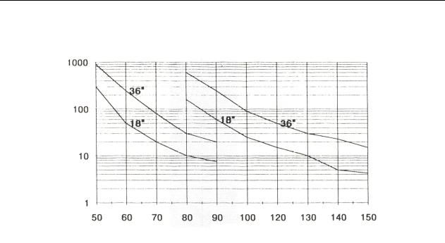
mAs Requirements |
See Figure 1-2 |
Reproducibility |
± 1 kV or 1%, whichever is greater |
Filtration Effects |
50 kVp - 90 kVp range: less than 3.5% with 5.3 mm aluminum |
|
added |
|
80 kVp – 150 kVp range: less than 3% with 8 mm aluminum |
|
added |
|
|
Calibration Frequency |
One (1) year |
Battery |
Type: 9 V alkaline, NEDA 1604 (IEC 6F22) or alkaline equivalent |
|
Life: 75 hr. typical |
|
|
Display |
3 ½ digit, 0.5" high LCD with LO BAT indicator; |
|
Below Range kVp: Flashing middle decimal point |
|
Above Range kVp: Flashing left decimal point |
|
Above Range mAs: Flashing right decimal point |
|
Below Range mAs: Flashing right decimal point and 00.0 |
|
display |
|
|
LED Indicators |
Auto Reset: New exposure detected, last kVp reading cleared |
|
Range Fault: Range select sliding filter not properly engaged |
|
|
Controls |
Power Switch: ON/OFF |
|
Phase Selection Switch: Single phase/3 phase |
|
Filter Range Selection Switch: 50 to 90 kVp or 80 to 150 kVp |
|
|
Connectors |
BNC connector for waveform output |
Dimensions |
2.5 in. x 8 in. x 6 in. |
(H x W x D) |
(6.4 cm x 20.3 cm x 15.2 cm) |
|
|
Weight |
2.4 lbs. (1.1 kg) |
Environmental Specifications |
Temperature: |
|
Operating: 59 to 104° F (15 to 40° C) |
|
Storage: - 0 to 122° F (-18 to +55° C) |
|
Relative Humidity: |
|
Operating: 0 to 90% non-condensing |
|
Storage: 0 to 90% non-condensing |
|
|
1-2
Victoreen 07-494
Operators Manual
.
mA
kVp
Figure 1-2. mAs vs. kVp, Minimum Requirements (Typical Single Phase X-ray Unit)
1-2

Victoreen 07-494
Operators Manual
(Blank page)

Getting Started 2
Receiving Inspection
Section 2
Getting Started
2.1 Receiving Inspection
Upon receipt of the instrument:
1.Inspect the carton(s) and contents for damage. If damage is evident, file a claim with the carrier and contact Fluke Biomedical, Radiation Management Services at 440.248.9300.
2.Remove the contents from the packing material.
3.Verify that all items listed on the packing list have been received and are in good condition. The following items are shipped with the Model 07-494 kVp Meter
a.Part No.168005, Model 07-494 kVp III.
b.Part No.16-29, 9 V Alkaline Battery
c.Part No.168001 Instruction Manual
d.Part No. 010023 Registration Card
NOTE
If any of the listed items are missing or damaged, notify Fluke Biomedical at 440.248.9300.
2.2 Storage
If necessary to store the kVp meter prior to use, pack it in the original container if possible. Be sure the storage area is free of corrosive materials, vibrations, and fluctuations in temperature and humidity. Also be sure the environmental specifications (refer to Section 1-2, Specifications) are not exceeded.
2.3 Routine Cleaning
CAUTION
Do not immerse the Model 07-494 Wide-Range Digital kVp Meter. This unit is not waterproof. Liquid could damage the circuits. The unit should be kept clean and free of dirt and contamination. The unit may be cleaned by wiping with a damp cloth using any commercially available cleaning or decontaminating agent.
2-1

Victoreen 07-494
Operators Manual
2.4 Indicators and Controls
Top Panel
The top panel (Figure 2-1) includes brief operating instructions, beam center indication, display guide for warning indicators A through D, and the range selector switch.
The range selector switch allows the operator to select the appropriate kVp range for the measurement. When the range selector is set to 80 - 150 kVp, a second filter pair is positioned above the photodiodes and a separate calibration is applied to the measurement circuit.
Front Panel
Refer to Figure 2-2 for front panel layout.
Numeric Readout: A 3-½ digit LCD display indicates the kVp value, provides warning status (flashing decimal points), and indicates low battery voltage (LO BAT). Warning indications are listed on the top panel and discussed further in Section 4, Operation.
Auto Reset LED: The auto reset LED is lit whenever the kVp Meter detects an x-radiation. The LED will be on for 0.5 seconds or for the duration of the exposure, whichever is greater. The previous reading is cleared when the LED turns on.
Range Fault LED: The range fault LED is lit whenever the range selector is between ranges or not properly engaged.
Power Switch (ON/OFF): The power switch is an alternate action switch used to turn the instrument on or off. The LCD readout is active when power is applied.
Phase Switch (1φ-3φ). The phase switch allows the operator to select either single phase (1φ) or threephase (3φ) operation. When the phase switch is in the 1φ position, the displayed value corresponds to a single-phase waveform produced by a single-phase x-ray machine. When the phase switch is in the 3φ position, the displayed value is the single phase calibrated output multiplied by a constant to compensate for differences between 3 phase (or DC) and single phase waveforms.
Figure 2-1. |
Top Panel |
2-2
Getting Started 2
Indicators and Controls
Figure 2-2. |
Front Panel |
Rear Panel
Refer to Figure 2-3 for rear panel layout.
Battery Access Cover: The battery access cover is located on the rear panel. Refer to Section 5, Maintenance for battery replacement procedures.
NOTE
Be sure the unit is turned OFF before removing the batteries.
BNC Connector: A BNC connector, located on the rear panel, provides a signal from the radiation detection diodes. The signal can be observed on an oscilloscope during an exposure. However, the signal lasts only as long as the exposure. Therefore, a storage scope or camera is required to view the signal for extended periods of time.
Scope |
CAUTION: Turn off power switch |
|
before replacing battery. Use |
|
MN16404 or equivalent alkaline |
|
|
Figure 2-3. |
Rear Panel |
2-3
Loading...