

Page 1
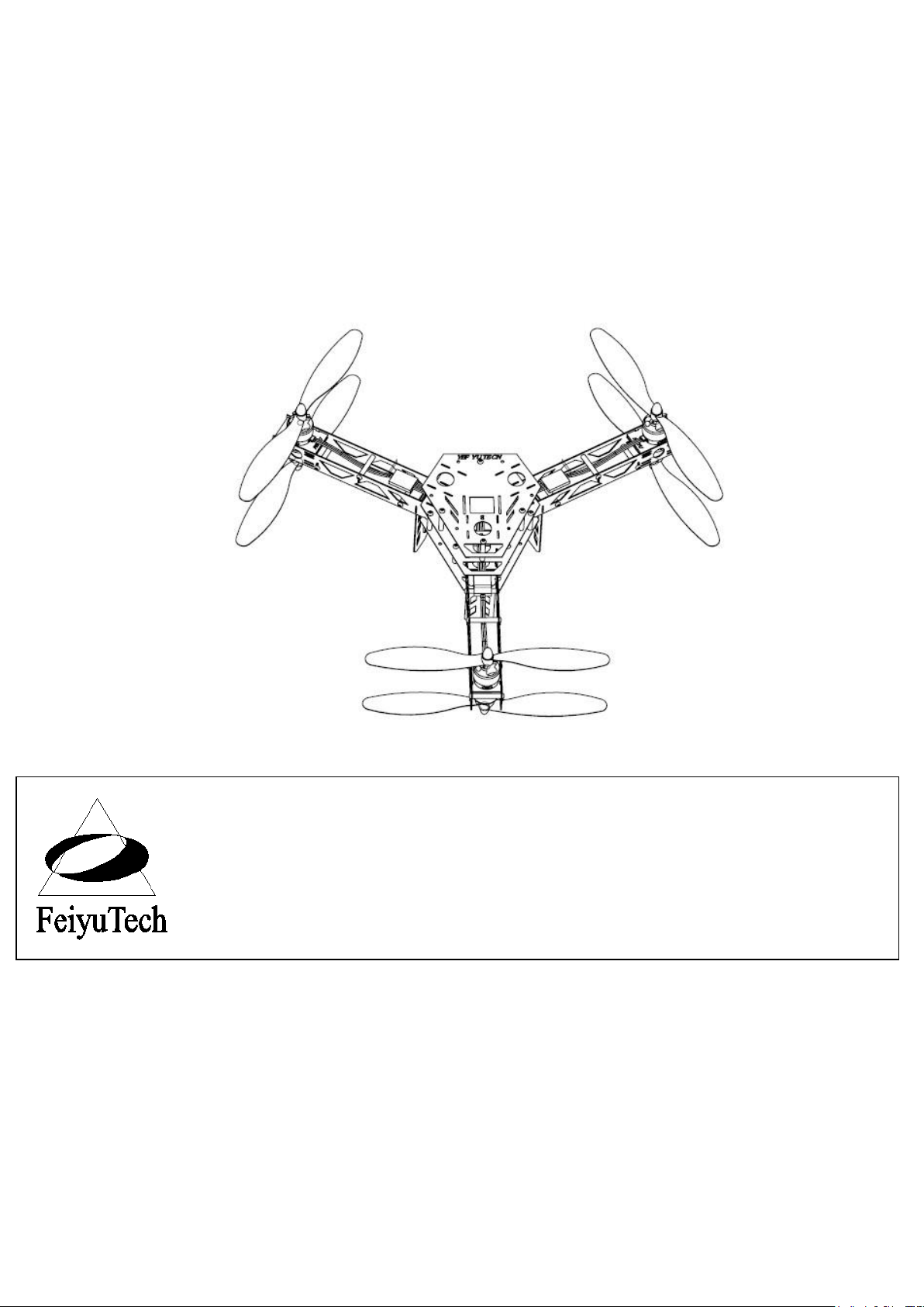
FeiYu Y6 scorpion Copter
Frame Instruction Manual
Please read the manual carefully before using FeiYu Y6
FeiYu Tech
Guilin Feiyu Electronic Technology Co., Ltd
4th Floor,Yu Tai Jie Science&technology Building, Information Industry Park,
ChaoYang Road ,Qi Xing District , Guilin 541004, China
http://www.feiyudz.cn
Email: service@feiyu-tech.com
Page 2
GuiLin FeiYu Electronic Technology Co., Ltd
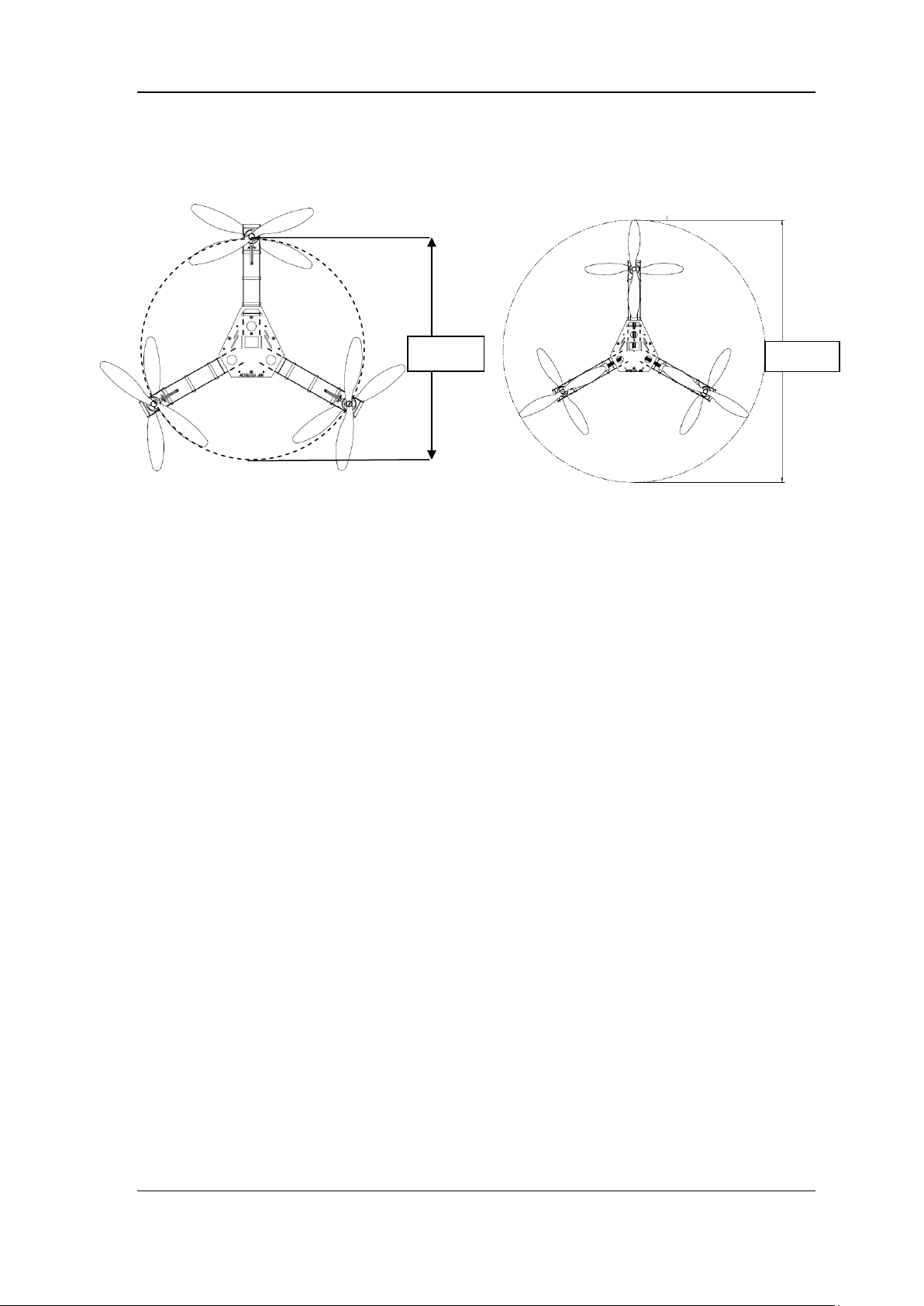
450mm
681mm
Features
1. Dimensions
2. Empty Frame Weight: 630g (receiver and battery not included)
3. Payload Capability: 900g ( battery, receiver, and camera included)
4. Maximum Gross Take-Off Weight: 1430g. DO NOT OVERLOAD ON FeiYu Y6 WHICH CAN
LEAD TO DANGER.
5. Airborne period: >10mins (with 3S 2200mAh battery)
6. Cell Chemistry: 3S 1500mAh ~ 5000mAh Lithium Polymer, and instant discharge capacity >15C.
Support PWM normal ESC.
7. Can install FY91Q. needs at least 4 channels to fly your aircraft. We recommend you to use RC
device with 5 channels or more for expansion. Support most.Compatible with all the RC devices.
Note:First and Foremost is Safety. This is Not A Toy. Used extreme caution when operating the Y6 .
Do Not Fly over Crowds or over people. Do Not use it as a chase copter.
GuiLin FeiYu Electronic Technology Co., Ltd www.feiyudz.cn E-mail: service@feiyu-tech.com
Page 1
Page 3
GuiLin FeiYu Electronic Technology Co., Ltd
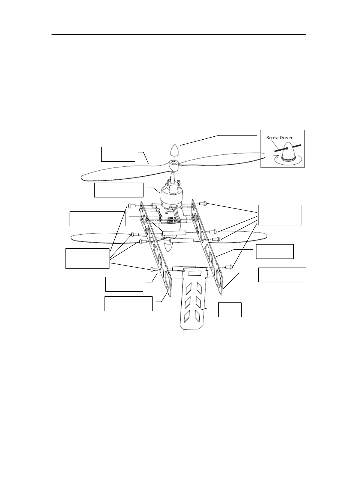
M3×5mm
M3*5mm
Brushless motro
prop
Leg
Right Arm
Left Arm
soldering point
soldering point
M3×30mm Pillar
Install
Tools needed to build the Y6:
Soldering Iron
Rosen Core Solder
Allen Wrench (provided)
Step 1:Frame Arm Assembly
Note: There are three LED on the side of arm,The LED should on out side.
Unpack the Frames, separate them as to color of l.e.d.’s i.e. Blue, Red, Green.
Remove the m3x5mm button head screws.
Remove the m3x30mm pillars.
Unpack the four motor mount plates.
Unpack the four motors.
Unpack the four landing gears.
Take a motor mount plate and using the allen wrench provided, attach the motor to the plate with four
m3x5mm button head screws. Lay this aside.
Take four m3x30 mm pillars, using the allen wrench and m3x5mm button head screw, attach the four
GuiLin FeiYu Electronic Technology Co., Ltd www.feiyudz.cn E-mail: service@feiyu-tech.com
Page 2
Page 4

GuiLin FeiYu Electronic Technology Co., Ltd
pillars to the holes in the side frame. Make sure that the led’s are facing to the outside. Take the
opposite side frame making sure the led’s are facing outwards and the Weld points are on the same end.
Do not tighten the screws yet, Now take the motor with it’s mount and position it in the bottom slots
that are cut in the side frames, snug down the button head screws for the motor. Now take the landing
gear and position it so the long end is pointing down. Now tighten all eight button head screws.
Go through the same procedure for the remaining three frames.
Inspect the assemblies to be sure that all the motors and the landing gears are seated properly.
When assembled properly, the Feiyu Tech Logo’s will be facing upright and the Welding points will all
be lined up.
Step 2:Building the Fuselage and attaching and Welding the Frames
to the Fuselage.
Unpack the three Frame assemblies. You will notice that they are marked with an “A” on one side
and a “B” on the other. The important one is the one with the Electronics mounted on it. Take eight
m3x25mm pillars and secure them with the button head screws . Make sure that the electronics are
facing up and the led plug is on the bottom. Take another fuselage plate in one hand and with the
other take a frame assembly, place the assembly with the weld points pointing down and insert it in the
slots provided on the electronics fuselage.
Take four button head screws and the fuselage plate and align the plate with the holes for the pillars,
making sure that the other die cut holes line up properly. Lightly screw the three button head screws
into the pillars, now take the remaining Frames and place them in the slots provided.
Once all frames are inserted into the top and bottom Fuselage plates, tighten the four button head
screws and insert the remaining four screws and tighten them as before.
Inspect the Frames and make sure that the weld points are seated snugly in their locations. If
necessary, loosen the screw(s) to properly fit the pieces.
GuiLin FeiYu Electronic Technology Co., Ltd www.feiyudz.cn E-mail: service@feiyu-tech.com
Page 3
Page 5

GuiLin FeiYu Electronic Technology Co., Ltd
Cross any two wire ,
change Motor rotation
welding
ESC
Fuselage with
Electronic
components
Magic cable
tie through
square groove
M3×25mm Pillar
Step 3: Welding (soldering) the frames to the bottom fuse plate
with the electronics.
To accomplish this you will need a small soldering iron aprox. 35w.
Plug in the soldering iron and while it is coming to temperature, gather your Rosen Core solder and
safety glasses.
With the soldering iron at temp. place the tip on the bottom fuse weld point, making sure that the tip
makes contact with both the frame and fuse weld points. Apply solder at this point, you will notice
that the solder will wik (Flow) smoothly and make a gusset. Make sure you don’t have a cold solder
joint. I needed, reheat the joint. Use caution as not to Over Heat the solder joints as this will cause
the metal to curl up and away from the contact point.
Follow this process for the remaining points.
Now remove the top Fuselage plate, this will gain you access to the weld points inside and between the
Frames.
Once inspected and sure that no cold solder joints are there. Connect a 3S Lipo Balance plug to the
plug on the bottom of the Fuselage.
You should have all the led’s lit and the bottom will light up White and will flash for a few seconds
then glow steady. If some of the led’s do not light , inspect all your weld points. You can also take a
GuiLin FeiYu Electronic Technology Co., Ltd www.feiyudz.cn E-mail: service@feiyu-tech.com
Page 4
Page 6

GuiLin FeiYu Electronic Technology Co., Ltd
Status
LED on
Slow flash
Medium flash
Fast flash
battery
>11.5V
11.1V~11.5V
10.8V~11.1V
<10.8V
note
Enough power
Voltage
reduction
Need landing
Landing
immediately
M3×30mm Pillar
M3×5mm
Front
M3×25mm Pillar
Power cable through
Round hole
6 ESCs wire
through out
volt meter and on DC range, check for proper voltage Aprox. 2.3vdc is present at the weld points.
Once you have the led’s inspected, remove the battery, place the fuselage you removed previously and
place eight button head screws in the corresponding holes and tighten them.
The Magic cable tie use for fixed battery.
The frame Power detection support 3S (11.1V )battery. Connect a 3S Lipo Balance plug to the plug on
the bottom of the Fuselage.
Power detection: Fuselage Led flash.
Step 4: Installing the ESC’s and the Battery connector.
Take the six esc’s out of their package, This is an important step to be observed. On five of the esc’s,
remove the “Red” positive lead from the servo connector. Place a small piece of Shrink tubing over
the wire as not to cause a short.
This is done as the FY91Q and the Compass module needs only one power source..
Connect the three blue wires with the female connectors to the motor leads. As for now you don’t
need to worry about direction the motor is turning.
Do this for all six motors and esc’s. Running the wires between the pillars and the sides of the frames,
poke the servo connectors up through the top Fuselage plate at each point corresponding to each motor.
Run each JST Battery male plug through the same hole as the servo lead.
Insert the male plugs from the Battery plug assembly as indicated on the photo, attach each Female
JST to each of the plugs.
GuiLin FeiYu Electronic Technology Co., Ltd www.feiyudz.cn E-mail: service@feiyu-tech.com
Page 5
Page 7

GuiLin FeiYu Electronic Technology Co., Ltd
2
3
6 5 1
Front
4
Y6 SCORPION FLYER
1 (top) = ESC 1 CW
2 (top) = ESC 2 CW
3 (top) = ESC 3 CW
4 (bottom) = ESC 4 CCW
5 (bottom) = ESC 5 CCW
6 (bottom) = ESC 6 CCW
cw = clock wise
ccw = counter clockwise
Propeller installation
Pay attention to the installation of the propeller direction.
——END——
Note: We reserve the right to change this manual at any time! And the newest
edition will be shown on our website www.feiyudz.cn.
GuiLin FeiYu Electronic Technology Co., Ltd www.feiyudz.cn E-mail: service@feiyu-tech.com
Page 6
 Loading...