

Guilin Feiyu Electronic Technology Co., Ltd
Addr : 4th Floor,YuTaiJie Science Technology Building,Information Industry Park ,
ChaoYang Road ,Qi Xing District ,Gui Lin ,541004
Website: www.feiyu-tech.com
Email: service@feiyu-tech.com
PandaⅡAutopilot System
Installation & Operation Manual
Apply To The Firmware V1.35 And Above Version

Guilin Feiyu Electronic Technology Co., Ltd.
Table Of Content
User Agreement ......................................................................................................................................1
1. PandaⅡAutopilot System Introduction ...........................................................................................2
2. Major Autopilot Components...........................................................................................................3
3. Technical Parameters .....................................................................................................................4
4. PandaⅡ Instructions .....................................................................................................................5
5. Connection Diagram .......................................................................................................................8
6. S1~S8 Servo Interface Connection Instructions ...........................................................................10
7. The Instructions Of Each Modules‘ Connection ............................................................................10
8. The Installation Of Main Module ...................................................................................................13
8.1 PandaⅡ Module Installation ................................................................................................13
8.2 GPS Module Installation .......................................................................................................14
8.3 Power Management Module Installation ...............................................................................14
8.4 Data Radio Module Installation .............................................................................................14
8.5 Airspeed Sensor Module Installation.....................................................................................15
9. PandaⅡ Indicator Light Instruction ..............................................................................................16
10. RC Unit Requires And Setting ......................................................................................................17
11. Parameter Setting Software (GCS)——USB Driver And GCS Software installation .....................18
12. Connection Between PandaⅡ And GCS Software ......................................................................19
12.1 Steps Of The Connection And Upload The Map ...................................................................19
12.2 Steps Of ID Number Reset ...................................................................................................21
13. Parameters Setting Process Of PandaⅡ Autopilot......................................................................23
14. PandaⅡAutopilot System Other Setting .......................................................................................31
14.1 Power Voltage Calibration ................................................................ ....................................31
14.2 Photograph Control ..............................................................................................................31
14.3 Automatic Take Off ................................................................................................ ...............32
14.3.1 Automatic Take Off Mode Setting .............................................................................32
14.3.2 Automatic Take Off Parameters Setting ....................................................................33
14.3.3 Process Of Automatic Take Off .................................................................................33
14.4 Automatic Landing................................................................................................................34
14.4.1 Automatic Landing Mode Setting ..............................................................................34
14.4.2 Automatic Landing Achieving ...................................................................................35
14.4.3 Automatic Landing Point Setting ..............................................................................36
14.5 RC Switch (SW2) Setting .....................................................................................................37
Guilin Feiyu Electronic Technology Co., Ltd http://www.feiyu-tech.com service@feiyu-tech.com

Guilin Feiyu Electronic Technology Co., Ltd.
14.6 Record Servo Neutral ...........................................................................................................38
14.7 POS Information Reading ....................................................................................................38
15. Route Planning .............................................................................................................................39
15.1 Route Planning In 2D View...................................................................................................39
15.1.1 Route Planning By Mouse Click ...............................................................................40
15.1.2 Regional Auto Route Planning..................................................................................41
15.2 Route Planning In 3D View...................................................................................................41
15.2.1 Route Planning In 3D View .......................................................................................42
15.2.2 Regional Auto Route Planning In 3D ........................................................................43
15.2.3 Route Planning By Mouse Click In 3D View .............................................................45
16. Checking And Suggestion For Fly ................................................................................................45
Appendix................................................................................................................................................48
Appendix A: Introduction For Other Functions And Settings .........................................................48
Appendix B: Adjust The Center Of Gravity....................................................................................52
Appendix C: Flight Area Map Making............................................................................................52
Appendix D: Voltage Calibration Operation...................................................................................55
Appendix E: Airspeed Sensor Installation And Calibration ............................................................56
Appendix F: POS Data Reading And Instructions .........................................................................57
Appendix G: Modify The COM Port Number .................................................................................59
Appendix H: Run The GCS As Administrator ................................................................................62
Appendix J: Fail Save Instructions ................................................................................................62
Appendix K: Photograph Caption Of The Camera Refit ................................................................63
Appendix L: PID Control----―Turn Ctrl‖ Parameter Adjustment. ..................................................... 64
Appendix M: Default Parameters Of PandaⅡ Autopilot...............................................................66
Appendix N: Firmware Upgrade....................................................................................................68
Guilin Feiyu Electronic Technology Co., Ltd http://www.feiyu-tech.com service@feiyu-tech.com

Guilin Feiyu Electronic Technology Co., Ltd.
Dear Pilot
Thank you for purchasing the PandaⅡ Full Function Autopilot with GCS & AFSS
from FeiYu Tech. In order to achieve full potential and safe operation of this product,
please carefully read this manual prior to installation.
This manual applies to PandaⅡ firmware V1.35 or above , GCS 5.23 or above
version .
User Agreement
a) The PandaⅡ autopilot system complies with all regulations within the People‘s
Republic of China (PRC).
b) It is the end user‘s responsibility to ensure compliance to regulations in their own
country if the PandaⅡ is used outside of the PRC.
c) PandaⅡ autopilot system is prohibited to be used for any illegal activity. It is the end
user‘s responsibility to take all safety measures in using this product.
d) The Guilin Feiyu Electronic Technology Co. (herewith known as Feiyu Tech) and our
associates are not responsible for any damages or liabilities caused by the use of this
product.
e) The PandaⅡ is internationally patented. It is unlawful to reverse engineer, copy or
modify this product in any way.
f) Feiyu Tech reserves the right to update, upgrade or modify the product at any time as
we see fit. We will to the best of our abilities inform existing users if such updates
need to be carried out in units already in use.
g) Feiyu Tech reserves the right to amend this manual and the terms and conditions of
use of the PandaⅡ at any time.
When purchase the product, this agreement automatically take effect.
Attention
The installation and use of this autopilot require advance skill and knowledge in
flying remote controlled fixed wing aircraft, the operations of amateur autopilot system
and ground control station (GCS).
If you are a complete beginner in autopilots, we do not recommend you install
this system on your own.
Please find assistance from an experience flier who may provide you with the
basic knowledge in autopilot systems to ensure successful installation and safe use
of this device. Alternately, you may gain experience by using our PandaⅡ first.
If you are already an experienced pilot and have used autopilot systems before,
you will find this step by step manual intuitive and logical. Just follow the instructions
as stated very carefully and you won‘t go wrong.
Please do not hesitate to e-mail us directly for assistance:
service@feiyu-tech.com
Guilin Feiyu Electronic Technology Co., Ltd http://www.feiyu-tech.com service@feiyu-tech.com
Page 1
Guilin Feiyu Electronic Technology Co., Ltd.
1. PandaⅡAutopilot System Introduction
PandaⅡ Autopilot system mainly include: PandaⅡ Autopilot module, GPS module,
Airspeed module, Power management module, Remote adapter module, communication
system, GCS. Through our GCS software you can set flight waypoint, flight altitude, flight
speed, Equidistance or Timing taking photo and so on. Also can control the aircraft to
Automated circling, Automated Return to Home (RTH), Automated take off and
Automated landing according the route setting. You can real-time change the flight task
during the flight, convenient and flexible operation, easy installation and debugging. In
addition there are many protected mode, can the greatest degree of guarantee reliable
and flight safety. Could be used for unmanned aerial vehicles (uavs) automatically
control or professional aerial photography.
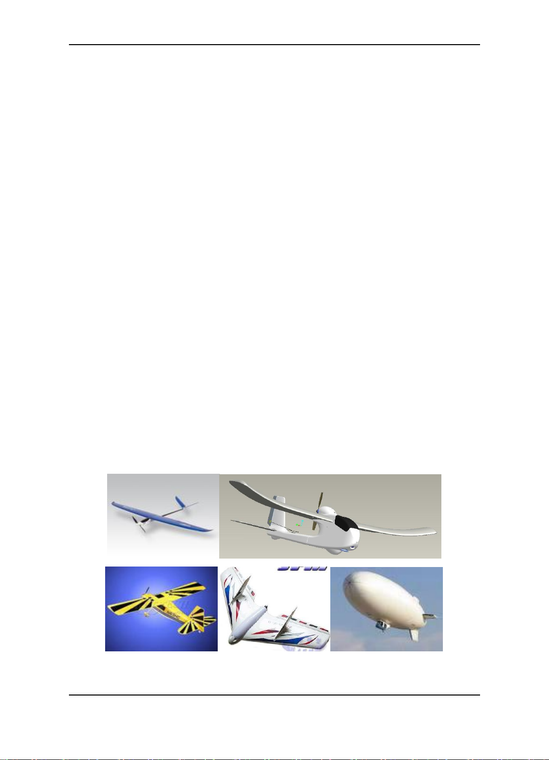
Aircraft Suitability
1. Normal / Traditional fixed-wing planes
2. Delta-winged plane with rudder
3. Delta-winged plane without rudder
4. Plane without aileron
5. V –tail plane with and without aileron
6. Any other configuration, please e-mail us for enquiry: service@feiyu-tech.com
Guilin Feiyu Electronic Technology Co., Ltd http://www.feiyu-tech.com service@feiyu-tech.com
Page 2

Guilin Feiyu Electronic Technology Co., Ltd.
2. Major Autopilot Components
1. PandaⅡ provides high-precision flight attitude measurement and control through the
utilization of an integrated 32 bits microprocessor, GPS receiver, three-axis MEMS gyros,
three-axis accelerometer, three-axis magnetic sensor, accurate barometric pressure
sensor, attitude algorithm, Kalman filtering and data fusion algorithms.
2. Combined the attitude module and the control module, get more small volume and lighter
weight.
3. Realize auto take off and auto land, maximum reduce the operating pressure.
4. Can accord to the plane internal space to adjust the install direction , easier to complete
the connection.
5. 10Hz data rate GPS receiver, 35 seconds fast positioning time and accuracy of 2.5
meters CEP. The GPS can record the positional parameter with battery , the locating time
greatly improved.
6. 100HZ inner attitude control, 10HZ outer navigation control.
7. Multi-channel mixed-control output can be adjusted with ease. The control options
include:
a) Elevator and rudder navigation
b) Elevator, aileron and rudder navigation
c) Elevator and aileron mixed-control (elevon) navigation
d) V-tail rudder may be used, however a third party mixer have to be supplied by the
user.
8. Three control modes:
a) Manual Mode ;
b) AFSS activated (Active Stabilization) ;
c) Automatic navigation control.
9. Two automated navigation control modes:
a) Air route navigation mode ;
b) Mouse controlled flight mode.
10. Three special flight modes:
a) Fixed circling mode;
b) Auto Return to Home (RTH) mode;
c) Auto take-off mode.
(On Auto Return to Home(RTH) mode, PandaⅡ has 50m altitude protection limited, if
the switch point altitude below 50m, PandaⅡ will automatic climb to 50m.)
11. Any standard RC transmitter and receiver can be used with this system.
12. Automated RTH (Return to Home) protection when there is a break in GCS
communication link via the data radios. This time the system is working only in the data
radio control mode.
13. Panda Ⅱ can Integrated automatic and manual aerial photography triggering.
Equidistance or Timing taking photo. Combine with the POS data record module can
record the current flight attitude info of the taking photo point, for example the Longitude,
Guilin Feiyu Electronic Technology Co., Ltd http://www.feiyu-tech.com service@feiyu-tech.com
Page 3

Guilin Feiyu Electronic Technology Co., Ltd.
Component
Min
Value
Standard
Value
Max
Value
Units
Remark
Main Supply Voltage
6.5 26
Volt
Main Supply Current
60 mA
At 5V supply
voltage
Altitude Measurement Range
-500
6000
Meter
GPS Ground Speed
Measurement Range
0 350
Meter/Se
c
GPS Horizontal Navigation
accuracy
2.5 Meter
Repeat Precision
Barometric Pressure Altitude
accuracy
2
Meter
Repeat Precision
Waypoints setting
98
98 point
programmable
Rudder Servo
3
Channel
Throttle Channel
1
Channel
Servo Output Frequency
1
µS Updated Servo Frequency
50 Hz
latitude, altitude, speed, etc .
14. The GCS software helps integrate Automated and Manual flight control modes in an easy
to use display interface.
15. The GCS software includes electronic map formatting. By using the electronic map,
aircraft route and tasks can be modified in real-time via your GCS computer.
16. Real time display on the GCS includes flight parameters such as main pack voltage, mAh
consumed, Amp draw, GPS satellite strength and temperature of the autopilot unit.
17. All flight parameters are downloaded automatically by the GCS for instant playback.
18. IMPORTANT: GCS Function
When using the Data Radio to control the aircraft, the controlling signals from the RC
Receiver is directly sent to the Remote Adapter and converted to digital signals. The
Data Radio will then upload the commands to your aircraft via the data radio.
The GCS is only used to monitor telemetry and flight status of the aircraft.
Transmission of commands is minimal. i.e. the aircraft is mainly controlled by your RC
Transmitter. The autopilot still can realize most of the functions (for example, air route
setting, RTH, circling) without the GCS.
19. Support the firmware update, can update by yourself.
3. Technical Parameters
Table 1.1: Unless specified, values are at operating temperature of 25 ℃.
Guilin Feiyu Electronic Technology Co., Ltd http://www.feiyu-tech.com service@feiyu-tech.com
Page 4
Guilin Feiyu Electronic Technology Co., Ltd.
Flight status PID Control Rate
100 Hz Navigation Control PID Rate
10 HZ
Data Telemetry‘s Track
Frequency
1
Hz
Maximum 10Hz
Data Telemetry‘s Mission
Frequency
1
Hz
Maximum 10Hz
Data Telemetry ‗s Flight Status
frequency
1
Hz
Maximum 10Hz
RS-232 Baud Rate
19200
Bps
TTL Level
Operating Temperature
-20
25
60 ℃
Temperature
25 ℃
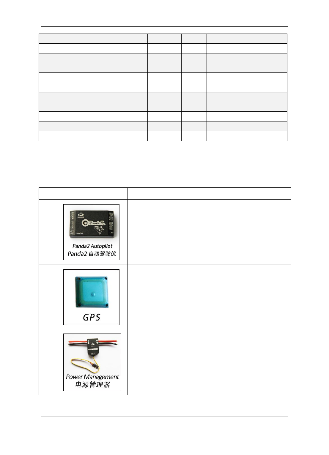
No.
Module
Instructions
1
PandaⅡ Control Module
Volume:57mm * 34mm * 19mm
Weight:34g
2
GPS Receiver Module
Volume:32mm * 32mm * 13.5mm
Weight:24g
3
Integrated current sensor, can power on PandaⅡcontrol
module
Volume:26mm * 39mm * 15mm
Weight:24g
4. PandaⅡ Instructions
Guilin Feiyu Electronic Technology Co., Ltd http://www.feiyu-tech.com service@feiyu-tech.com
Page 5
Guilin Feiyu Electronic Technology Co., Ltd.
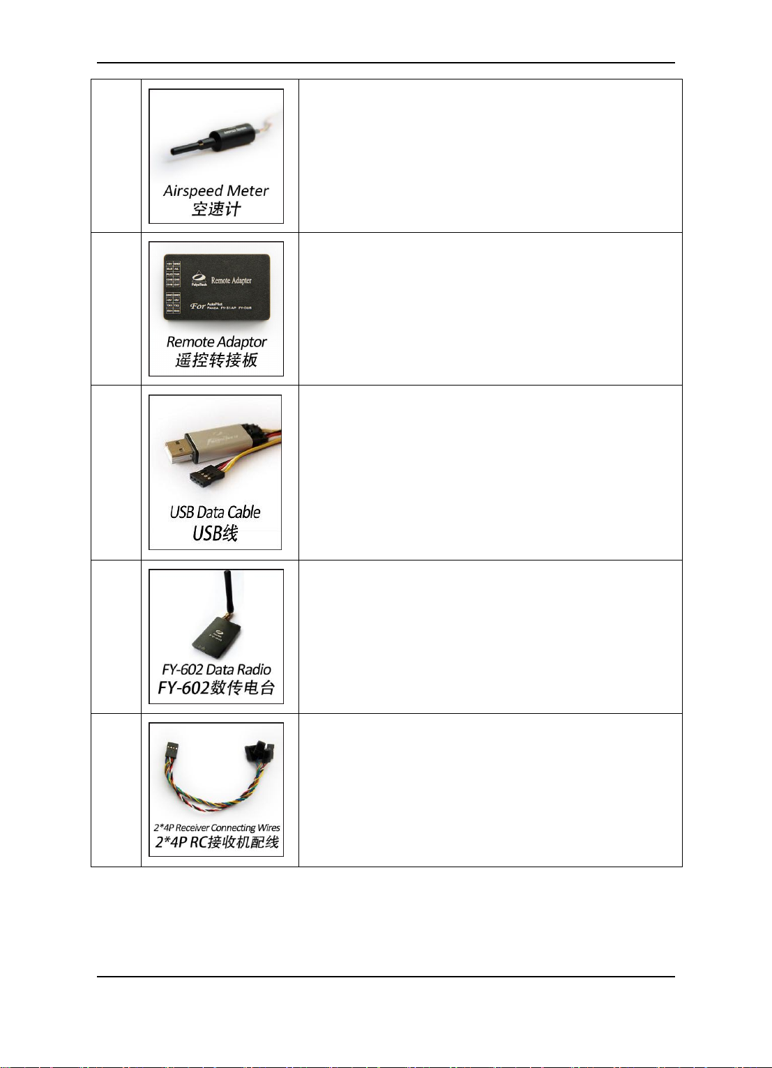
4
Use for measure the airspeed
volume:64.5mm * 13.5mm * 13.5mm
Weight:9g
5
Turning receiver signal to digital signal for data radio
Volume:52mm * 33.5mm * 14mm
Weight:26g
6
1.Connect Data Radio and PC
2.Connect Remote Adapter and PC
3.Use for PandaⅡ firmware upgrade
7
Used as the wireless data transmission between
PandaⅡ and GCS
Power:500WM
Frequency:433MHZ(default) / 915MHZ
Communication distance:10KM(unobstructed)
Volume:64*41*12mm
Weight:43g
8
Use for connect PandaⅡ and RC receiver
Guilin Feiyu Electronic Technology Co., Ltd http://www.feiyu-tech.com service@feiyu-tech.com
Page 6
Guilin Feiyu Electronic Technology Co., Ltd.
9
Use for connect Remote Adaptor and RC receiver
10
Use for connect Data radio and USB data cable
11
GPS extension cord
12
Attention: If you do not use the ESC to power on the
servos, you can connect external power source to power
on the servos through P2 port.
13
Connect to the taking photo port of the camera.(Need to
do the camera shutter transformation)
Guilin Feiyu Electronic Technology Co., Ltd http://www.feiyu-tech.com service@feiyu-tech.com
Page 7
Guilin Feiyu Electronic Technology Co., Ltd.
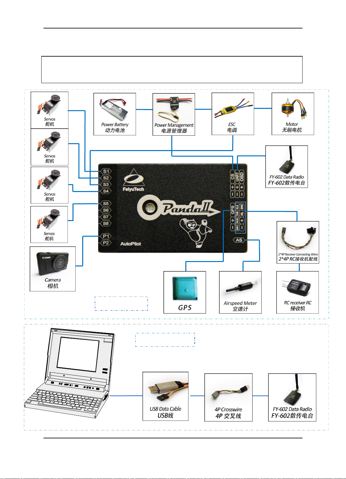
OPTION 1 (“RC” control mode): RC receiver directly connect to Panda Ⅱ. The maximum
flight range depend on your RC Transmitter. No delay, high real-time performance.
Aircraft
Ground Station
5. Connection Diagram
Guilin Feiyu Electronic Technology Co., Ltd http://www.feiyu-tech.com service@feiyu-tech.com
Page 8
Guilin Feiyu Electronic Technology Co., Ltd.
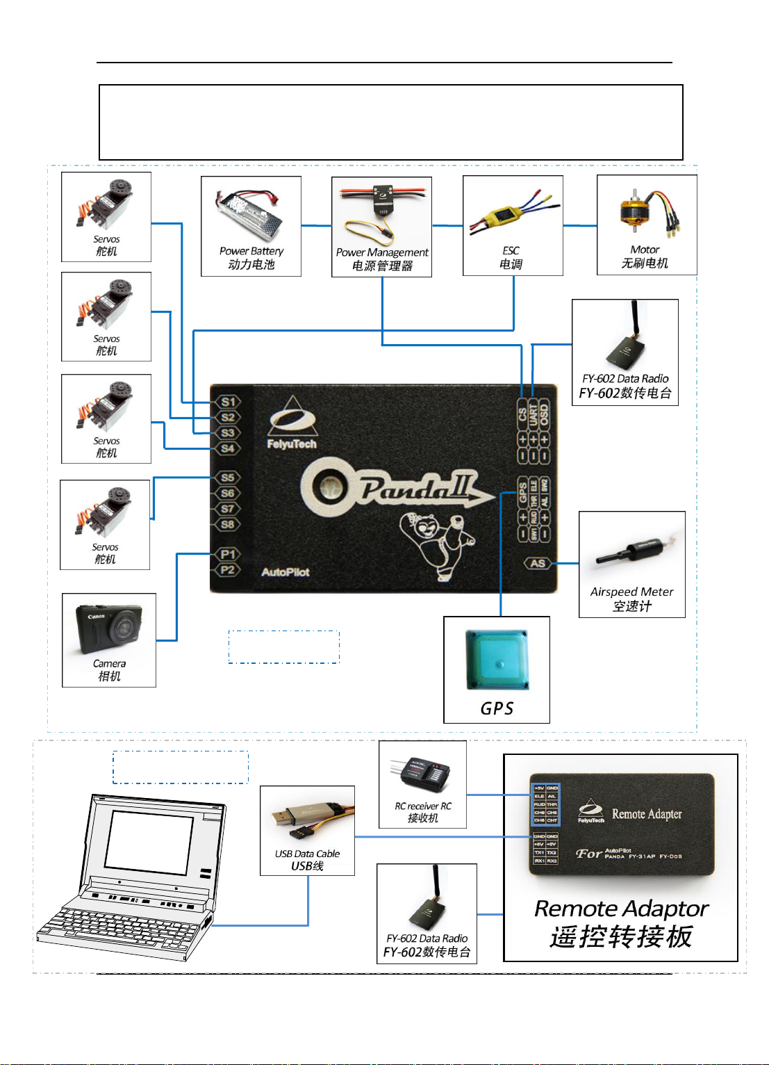
OPTION 2 (“DDRC” control mode ): The Data Radio range will dictate your flight range.
Additionally, due to the digital signal conversion and processing, some delay in manual control
transmission will occur
Aircraft
Ground Station
Zz
z
Guilin Feiyu Electronic Technology Co., Ltd http://www.feiyu-tech.com service@feiyu-tech.com
Page 9
Guilin Feiyu Electronic Technology Co., Ltd.
No.
Type
Traditional
Flying wing
V tail
Airship
S1
Aileron servo 1
Aileron &Elevator mix
control servo 1
Aileron servo 1
Not use
S2
Elevator servo
Aileron &Elevator mix
control servo 2
Elevator &Rudder
mix control servo 1
Elevator servo
S3
Throttle servo/ESC
Throttle servo/ESC
Throttle servo/ESC
Throttle
servo/ESC
S4
Rudder servo
Not use
Elevator &Rudder
mix control servo 1
Rudder Servo
S5
Aileron servo 2
Not use
Aileron servo 2
Not use
S6
Not use
Not use
Not use
Not use
S7
Not use
Not use
Not use
Not use
S8
Not use
Not use
Not use
Not use
Connection Diagram
Institutions
S1 ~ S8 servo connecting wires,
please pay attention to the direction
of signal line .
常规布局
6. S1~S8 Servo Interface Connection Instructions
7. The Instructions Of Each Modules’ Connection
Guilin Feiyu Electronic Technology Co., Ltd http://www.feiyu-tech.com service@feiyu-tech.com
Page 10
Guilin Feiyu Electronic Technology Co., Ltd.
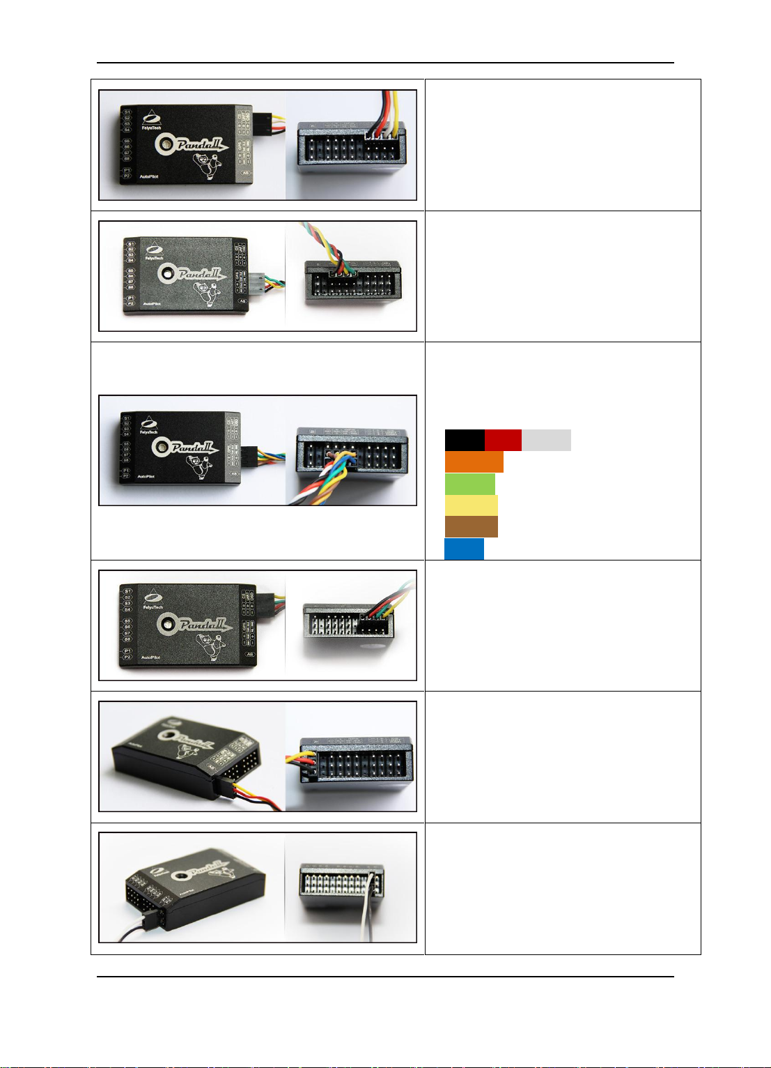
The wire connection about power
management module.
The wire connection about GPS
module.
2*4P RC receiver connecting wires,
use for connect the RC receiver and
PandaⅡ,the wires is arranged by
the colors.
Black Red White —— AIL
Orange —— ELE
Green —— THR
Yellow —— RUD
Brown —— CH5
Blue ——CH6
The FY-602 Data radio connecting
wires.
The Airspeed sensor connecting
wires.
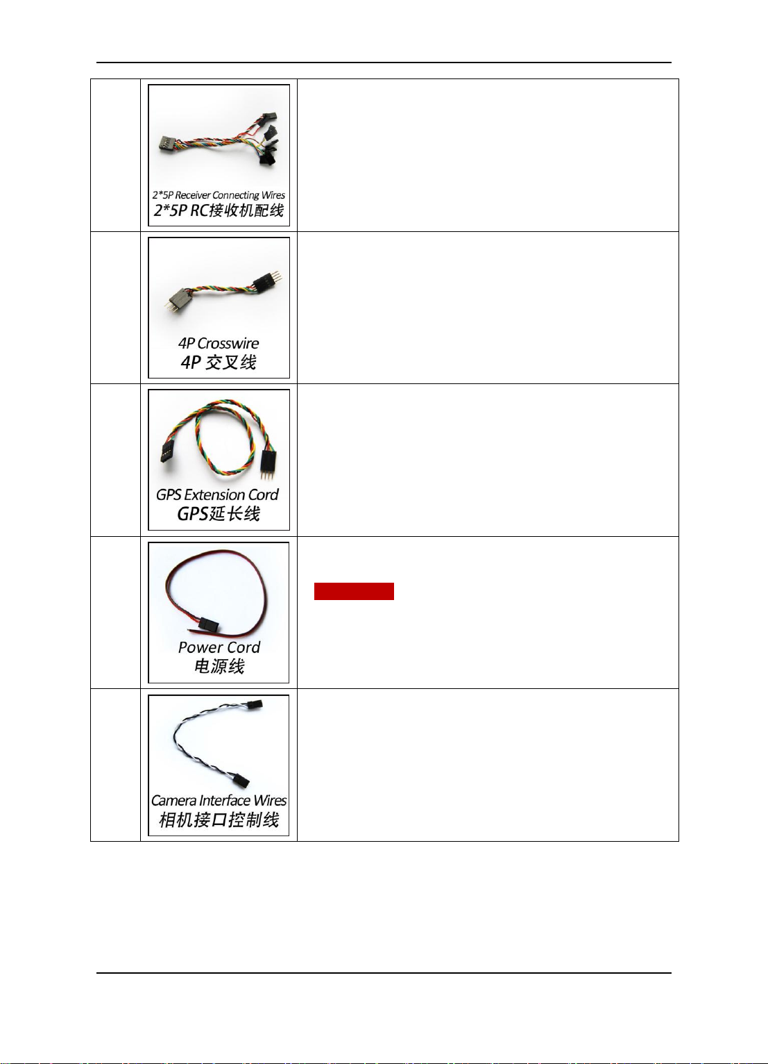
The wire connection about camera
control port P1, white(signal),
black(GND).
Guilin Feiyu Electronic Technology Co., Ltd http://www.feiyu-tech.com service@feiyu-tech.com
Page 11
Guilin Feiyu Electronic Technology Co., Ltd.
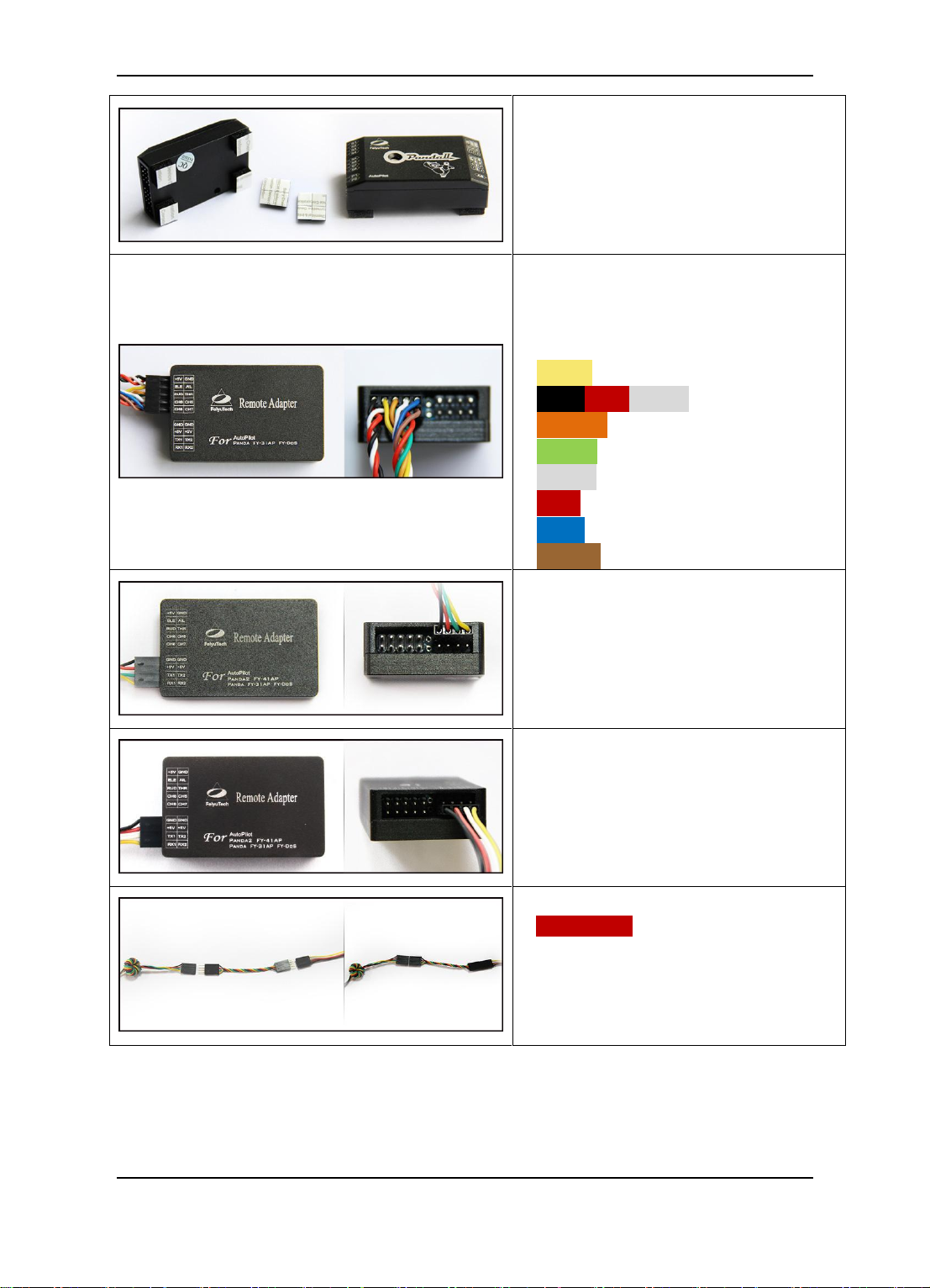
Vibration absorbing pads
(dampers),use for PandaⅡvibration
damping installation.
2*5P RC receiver connecting wires,
use for connect the RC receiver and
Remote Adaptor, the wires is
arranged by the colors.
Yellow —— AIL
Black Red White —— ELE
Orange —— THR
Green —— RUD
White —— CH5
Red —— CH6
Blue —— CH7
Brown —— CH8
The wire connection about Remote
Adaptor and FY-602 Data radio.
The wire connection about Remote
Adaptor and USB data cable.
Attention: You must use the 4P
crosswire like picture left shows,
when you connect the USB data
cable and FY-602 data radio.
Guilin Feiyu Electronic Technology Co., Ltd http://www.feiyu-tech.com service@feiyu-tech.com
Page 12
Guilin Feiyu Electronic Technology Co., Ltd.
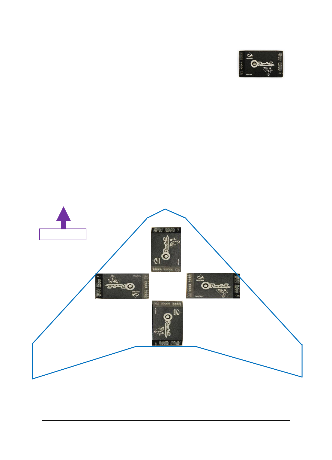
Nose of the plane
Arrow Forward (Default Direction)
Arrow Towards To Left
Arrow Towards To Right
Arrow Towards To Back
8. The Installation Of Main Module
8.1 PandaⅡ Module Installation
The Autopilot module must be placed horizontally and as close as possible to the
plane‘s CG (Center of Gravity). The default direction is the arrow direction must be
pointing towards the nose of the plane (i.e. direction of flight). You can change the
direction to four directions via the GCS software, i.e direction forward, back, left, right.
When installing the autopilot module please make use of the supplied damper mount
or other DIY vibration damping device, especially on gasoline aircraft. Otherwise the
vibrations will cause a large data inconsistencies which will adversely affect the autopilot
accuracy.
Guilin Feiyu Electronic Technology Co., Ltd http://www.feiyu-tech.com service@feiyu-tech.com
Page 13

Guilin Feiyu Electronic Technology Co., Ltd.
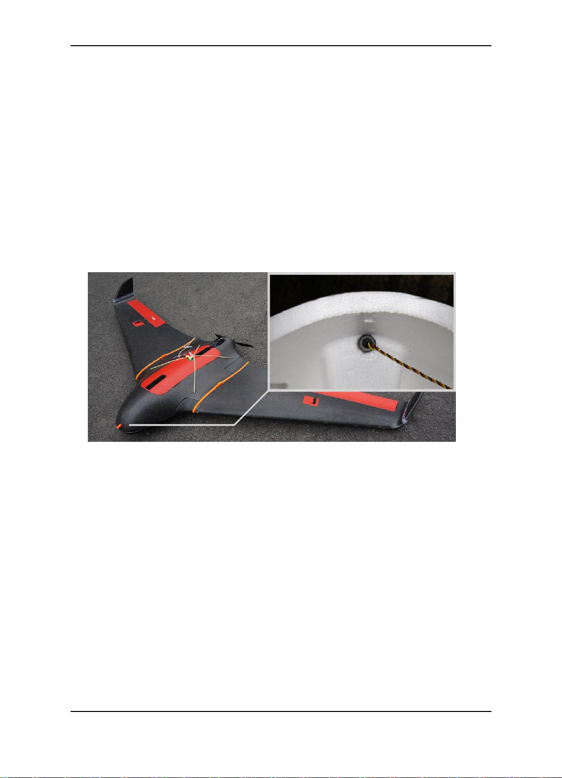
8.2 GPS Module Installation
GPS module including a flat-GPS passive antenna. This is a sensitive antenna for
GPS signals, while false signals reflected from the ground is effectively filtered out. Install
the GPS unit horizontally. Keep metal objects and other conductive materials such as
carbon fibre away from the GPS unit. Additionally no transmitting antenna should be
around the GPS antenna. The communication link antenna (Data Radio) or your video
transmitter should be kept as far away from the GPS unit as possible.
8.3 Power Management Module Installation
The power management module is used to connect the power battery and ESC,
which integrates a current sensor, can measure the power current and voltage, the
internal integrated DC-DC module will output a stable voltage which about 5.3V to power
on PandaⅡ. The control part and the servos power port is isolated on the PandaⅡ
module, so the power management module can not power on the servos .The servos still
need to power on through the ESC from S3 port or external power source from P2 port.
8.4 Data Radio Module Installation
The Data Radio module should placed away from the GPS module , PandaⅡ
module and the servos as far as possible, in order to avoid the disruption of these
devices. The Data Radio antenna should be vertically up or down when you install it .
Certain frequency bands from the Data Radio can interfere with servos due to
electromagnetic emission. To resolve this issue either avoid placing the Data Radio
transmitter close to sensitive components or use a magnetic core (as shown below) to
reduce the interference.
Guilin Feiyu Electronic Technology Co., Ltd http://www.feiyu-tech.com service@feiyu-tech.com
Page 14
Guilin Feiyu Electronic Technology Co., Ltd.
8.5 Airspeed Sensor Module Installation
The airspeed sensor need to pull ahead the front of the pneumatic opening and in
the line with the direction of flight. You can install the Airspeed sensor to the wing or in
the front of the nose, do not block the front of the air inlet, we can use the glue to fix the
airspeed sensor.
Make sure that after installation, the fuselage in flight airflow can not interfere
with air intakes.
Please calibrate the airspeed sensor in the first fly, skill of calibration please
refer to the Appendix E.
Guilin Feiyu Electronic Technology Co., Ltd http://www.feiyu-tech.com service@feiyu-tech.com
Page 15
Guilin Feiyu Electronic Technology Co., Ltd.
Red
Manual Mode, GPS not lock
Red—Red—Green
Stabilized Mode, GPS lock
Purple—Purple—Green
Stabilized Mode, GPS lock,
If it stay static means need Gyro Reset.
Blue—Blue—Blue—Green
Waypoint Navigation Mode, GPS lock
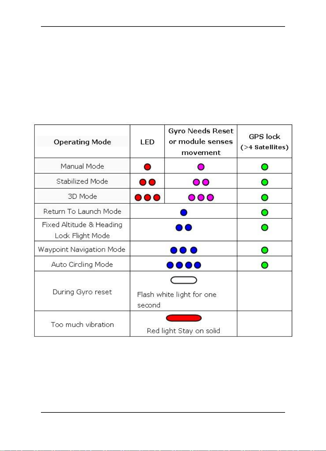
9. PandaⅡ Indicator Light Instruction
LED on the PandaⅡ module can send out red, blue, green and purple light.The
working statue can be know via the different colors which the LED sends out and the
flash frequency. green light flash means GPS location fixed, red and blue light indicate
PandaⅡ working mode. Under manual mode, stabilization mode or 3D mode, keep
PandaⅡ in the static state and if the LED sends out purple light it means PandaⅡ
needs Gyro Reset.
e.g.
Guilin Feiyu Electronic Technology Co., Ltd http://www.feiyu-tech.com service@feiyu-tech.com
Page 16
Guilin Feiyu Electronic Technology Co., Ltd.
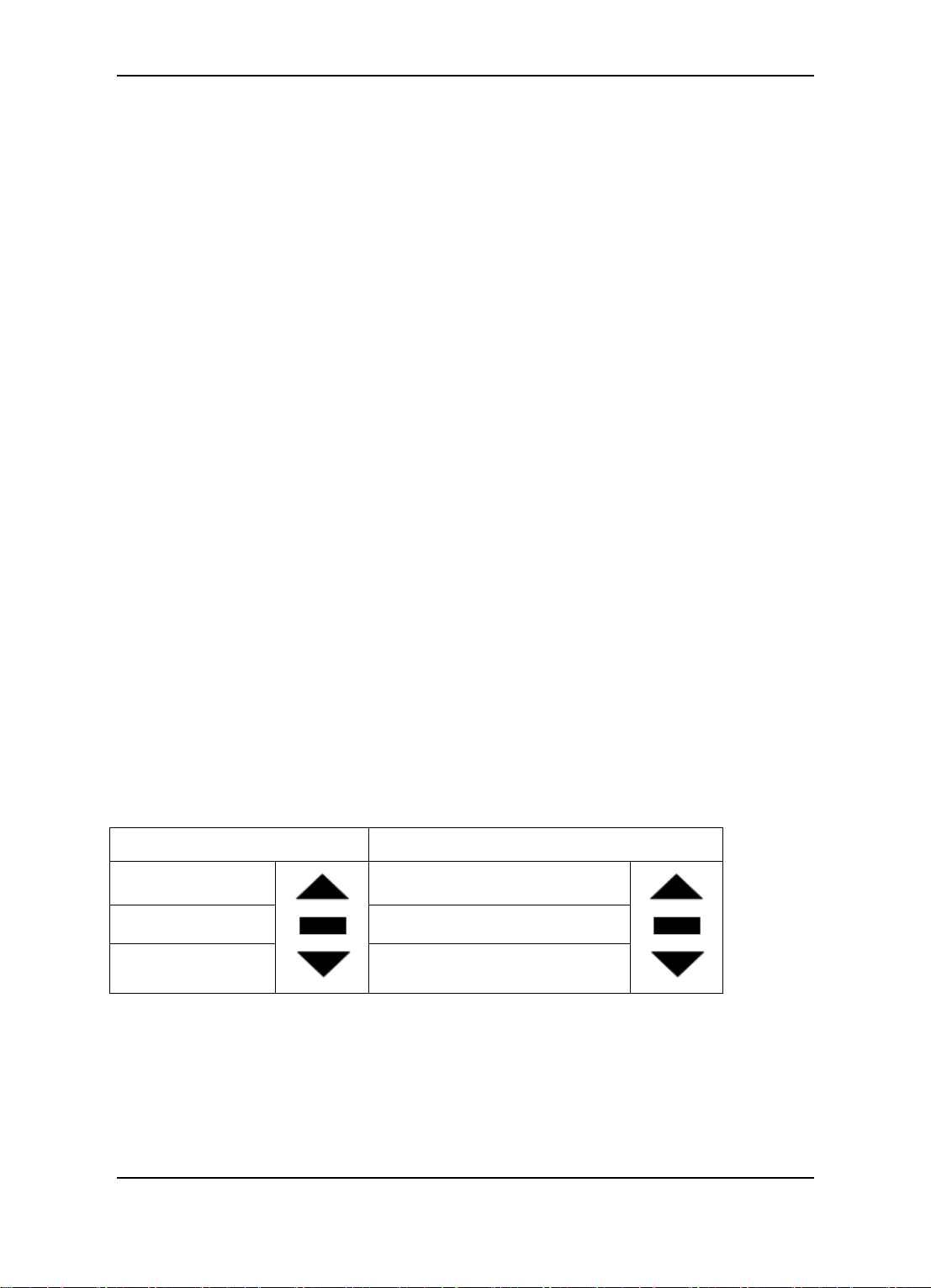
SW1
SW2
Manual Mode
Waypoint Navigation Mode
Stabilized Mode
NULL
3D Mode
Return To Launch Mode
10. RC Unit Requires And Setting
PandaⅡ requires a minimum of 6-channel RC receiver.4 Receiver channels are
used for aileron (channel 1), elevator (channel 2) ,throttle (channel 3) and rudder
(channel 4) signal output. 2 free Receiver channels are required to control the PandaⅡ
Flight Modes (a 3-position switch or dial knob, ‖SW1‖) and Navigation Mode (a 3-position
switch or dial knob, ‖SW2‖).
RC mode setting of your controller has to be fixed wing mode and cancel all mix
control setting.
PandaⅡ need two 3-position-switch to control the flight mode. One SW1 used for
control manual mode, stabilized mode and 3D mode, this can not be set. Another one
SW2 used for setting Auto Return To Launch Mode and Waypoint Navigation Flight
Mode(default) or Auto Circling Mode and Fixed altitude & Heading lock Mode. If need to
set up please refer to the section 14.5 RC switch setting.
SW2 has priority over SW1. Only when SW2 is in the ‗Null‘ Mode can SW1 work.
Therefore ‗Null‘ should be one of the options for SW2, otherwise SW1 will not work.
After set up switch mode, you can switch to the corresponding position then observe
the LED flashing situation to confirm whether the setting is correct or not.The details
please refer to section "9 Pnada2 indicator light instruction"
RTL mode、Line mode、Path Navigation mode、ACM mode are navigation
working modes, only when the GPS location fixed all of this navigation mode
can be activate effective.
SW1&SW2 default setting:
Guilin Feiyu Electronic Technology Co., Ltd http://www.feiyu-tech.com service@feiyu-tech.com
Page 17
Guilin Feiyu Electronic Technology Co., Ltd.
11. Parameter Setting Software (GCS)——USB
Driver And GCS Software installation
Step A : Please visit the official website: www.feiyu-tech.com. Download the correct
USB driver, GCS installation program and the Google Earth plug-in 6.1 or
above version then unzip the RAR file.
Step B : Install the USB driver according to the guide.
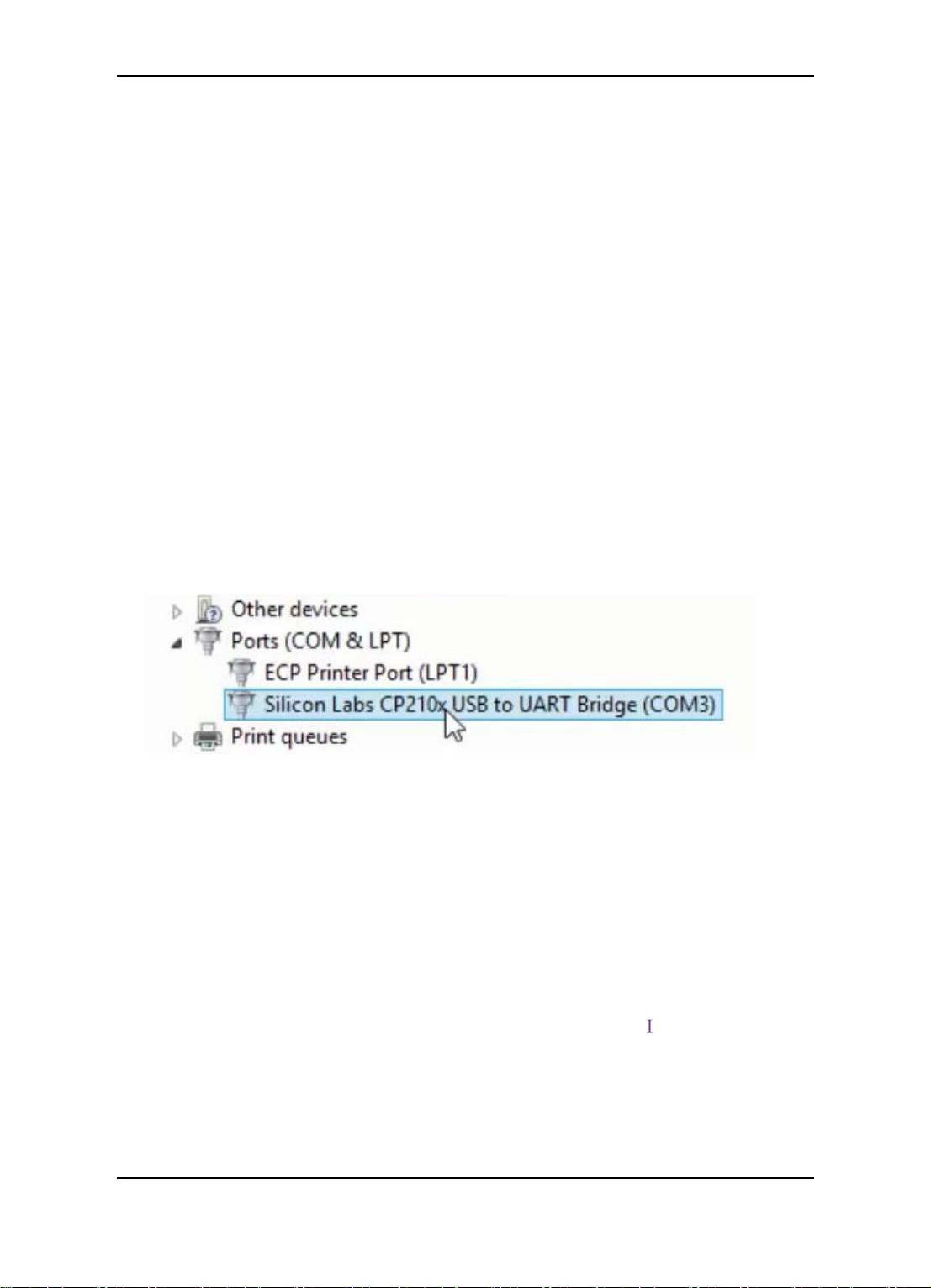
Step C : After successfully install the USB driver, insert the USB-TTL interface cable
into computer USB COM port(don‘t connect TTL port to any other device ) , the system
will correctly identify the USB -TTL data cable, then you will find there is a new port
add(COM and LPT) .―Silicon Labs CP210x USB to UART Bridge (COM3)‖.The ―COM*‖ is
what the connection need (e.g. COM3).
If the COM number is more than COM10, please modify to the available port which
lees than COM10 (Skill of modification please refer to the Appendix F ).
Step D : Install the GCS software according to the guide (Please install with the default
path).
Step E : Install the Google Earth plug-in 6.1.
The USB driver and the GCS software can be support the operation systems:
Windows XP, Windows 7, Windows 8, Windows 8.1, Windows Vista
Please run the GCS software as administrator when work with the Windows 7,
Windows 8, Windows 8.1, Windows Vista operation system. Steps for how to
run the GCS as administrator please refer to the Appendix
Guilin Feiyu Electronic Technology Co., Ltd http://www.feiyu-tech.com service@feiyu-tech.com
Page 18
Guilin Feiyu Electronic Technology Co., Ltd.
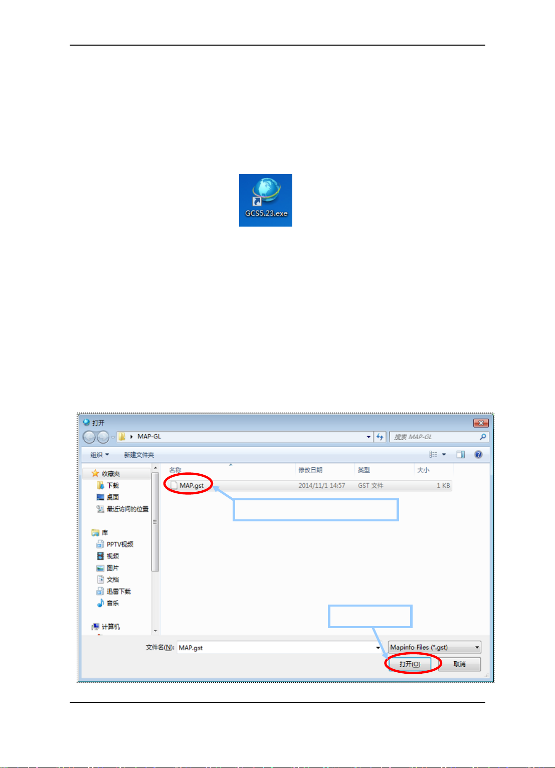
1. Select the Pre-made to the map
2. Click ―Open‖
12. Connection Between PandaⅡ And GCS
Software
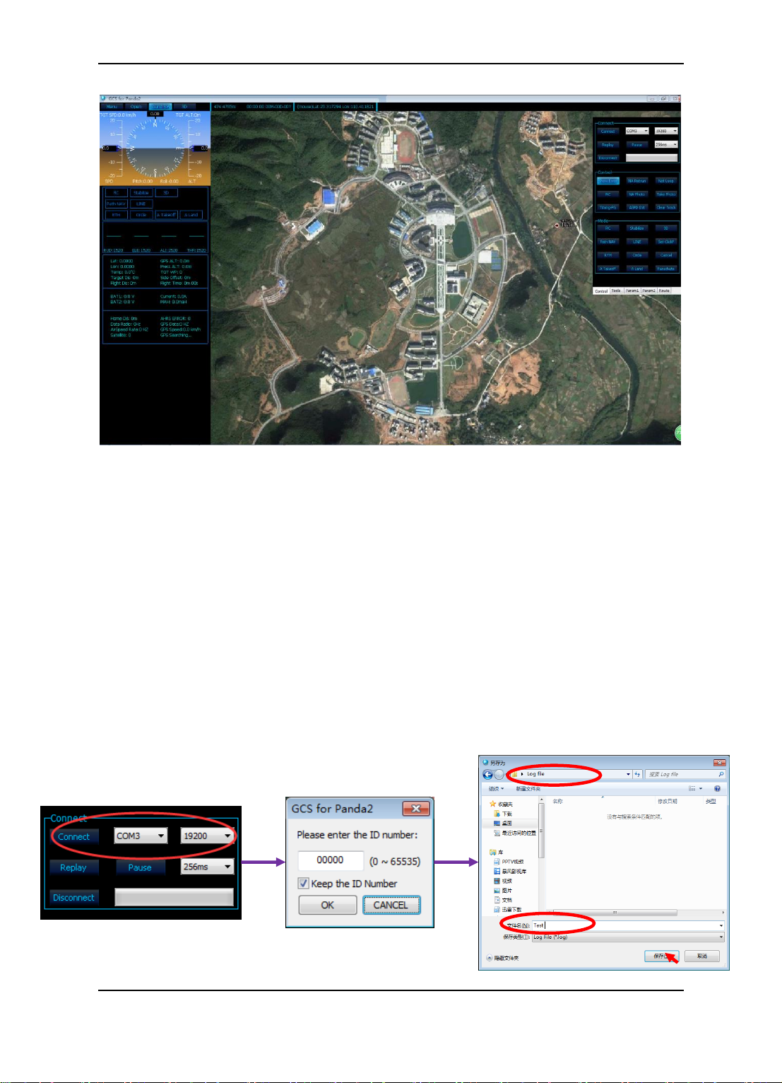
12.1 Steps Of The Connection And Upload The Map
Step A : Assumption the Autopilot system have installed ,connect to the computer
and power on normally.
Step B : Double click the icon ― ‖ start the software.
Step C : Select the correct COM port (e.g. COM3),baud rate:19200,click on
―Connect‖ button.
Step D : Enter the ID number in the pop-up ID setting dialog box(The default number
of the PandaⅡ is ―00000‖ ),click on ―OK‖ button.
Step E : Choose the save path and rename the file in the pop-up dialog box then
click on ―Save‖ button to save the log file of flying. Connection between
PandaⅡ and GCS finish.
Step F : Click on ―Open‖ button on the GCS select the *. gst files, click on ―Open‖
button uploaded the map to the software(Skill of map making please refer to
the Appendix B ).
Guilin Feiyu Electronic Technology Co., Ltd http://www.feiyu-tech.com service@feiyu-tech.com
Figure Load Interface
Page 19
Guilin Feiyu Electronic Technology Co., Ltd.
Figure Map Information Interface
After finish the Step E, if the current parameters of the autopilot can be display
on the GCS, it will indicate that the connection is successful.
The ID number can be reset by users. The new number please select
from“00000” to “65535”.If the number of characters more than 5 ,the ID
number will invalid.
The ID number reset operation support under the “OPTION1 (RC control
mode )” and “OPTION2 (DRRC control mode)”.
Connection diagram.
Guilin Feiyu Electronic Technology Co., Ltd http://www.feiyu-tech.com service@feiyu-tech.com
Page 20

Guilin Feiyu Electronic Technology Co., Ltd.
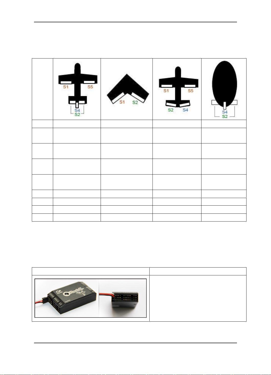
12.2 Steps Of ID Number Reset
Step A : Power off the autopilot unit .
Step B : Install the jumper to the signal pin on P1,P2 port ( Refer to the picture 12.1).
Step C : Connect the Autopilot unit to the computer (Ensure power on the unit normally).
Step D : Running the GCS software , select the correct COM port (e.g. COM3),baud
rate:19200,click on ―Connect‖ button.
Step E : Enter the new ID number (e.g. ―01234‖) in the pop-up ID setting dialog box, click
on ―OK‖ button.
Step F : Choose the save path and rename the file in the pop-up dialog box then click on
―Save‖ button to save the log file.
Step G : Select ―Menu---Autopilot Bound‖ on the GCS, the GCS software will prompt
“Autopilot Bound Success!”to remind the resetting successful ( Refer to the
picture 12.2)
Step H : Disconnect the unit, power off the autopilot unit ,uninstall the jumper .
Please remember the new number for the next connection.
If the ID number have lost , please reset refer to the “Step A” to “Step H”.
Figure 12.1 Jumper Install
Guilin Feiyu Electronic Technology Co., Ltd http://www.feiyu-tech.com service@feiyu-tech.com
Page 21

Guilin Feiyu Electronic Technology Co., Ltd.
Figure 12.2 ID Bounding Diagram
Guilin Feiyu Electronic Technology Co., Ltd http://www.feiyu-tech.com service@feiyu-tech.com
Page 22

Guilin Feiyu Electronic Technology Co., Ltd.
13. Parameters Setting Process Of PandaⅡ
Autopilot
Select ―Menu---Autopilot Configuration Wizard‖ begin doing basic configuration.
Step One: Installation direction setting
Set up the correct mounting direction according to the PandaⅡ mounting direction
on the plane(The default setting is Arrow forward).Click on the button "Set" after you
select the correct mounting direction. After that, pitch and roll inclined the plane through
the attitude Chart to check whether the posture and aircraft state is identical.
Guilin Feiyu Electronic Technology Co., Ltd http://www.feiyu-tech.com service@feiyu-tech.com
Page 23

No.
Normal
Elevon
V tail
Airship
Option
No MIX
ELE&AIL MIX
ELE&RUD MIX
No MIX
Guilin Feiyu Electronic Technology Co., Ltd.
Step Two: Servo’s output mix control mode setting
Set up the correct mixing mode according to the layout of the aircraft. The default
setting is‖ Normal (AIL NAV)‖. Click on the button "Set" after you select the correct mixing
mode.
―AIL NAV‖ means using only aileron make a turn in navigation mode.
―RUD NAV‖ means using only rudder make a turn in navigation mode.
Guilin Feiyu Electronic Technology Co., Ltd http://www.feiyu-tech.com service@feiyu-tech.com
Page 24

Guilin Feiyu Electronic Technology Co., Ltd.
Step Three: Servo control reverse setting
( 1 ) Aileron, Elevator, Throttle, Rudder auto control surface
direction setting
Operate the RC control sticks to control the aircraft servos movement to observe if
they are in the same control direction with the RC sticks. And if not, please adjust the RC
to make them correct.
Switch to the "Auto Balance Mode" mode after set up the RC unit, check the auto
control direction.
Guilin Feiyu Electronic Technology Co., Ltd http://www.feiyu-tech.com service@feiyu-tech.com
Page 25

Guilin Feiyu Electronic Technology Co., Ltd.
Downward
Upward
Nose Up
Nose Down
Aileron ( Check In "Auto Balance Mode" )
Right roll the aircraft, the right aileron should automatically move downwards, while
the left aileron move up.
Left roll the aircraft, the left aileron should automatically move downwards, while the
right aileron should move up.
If the servo movement is incorrect, please select ―AIL REV‖.
Elevator ( Check In "Auto Balance Mode" )
Upward incline the aircraft nose, the elevator should automatically move
downwards.
Downward incline the nose, elevator should automatically move upwards.
If the servo movement is incorrect, please select “ELE REV”.
Guilin Feiyu Electronic Technology Co., Ltd http://www.feiyu-tech.com service@feiyu-tech.com
Page 26

Guilin Feiyu Electronic Technology Co., Ltd.
Turn left
Rudder moves to the right
Turn right
Rudder moves to the left
Rudder ( Check In "Auto Balance Mode" )
Clockwise rotate the aircraft, the rudder should move to the left.
Counter clockwise rotation, the rudder should move to the right
If the servo movement is incorrect, you need to reverse the automated servo
movement please select “RUD REV”.
Throttle
Warning: It is recommended that remove the prop or disable the motor while
performing these setup procedure.
Pleases refer to the throttle output at the servo display as shown to the right. With
the throttle at the lowest setting the number should read 1000. As the throttle up this
number should get larger. If instead the number reads 2000 and gets smaller as you
increase the throttle please select “THR REV”
(2)Parachute servo direction setting
Parachute servo have to plug to S8 on the PandaⅡ.When the PandaⅡ autopilot
system power on and start normally ,the parachute servo will revert to its default position
Guilin Feiyu Electronic Technology Co., Ltd http://www.feiyu-tech.com service@feiyu-tech.com
Page 27

Guilin Feiyu Electronic Technology Co., Ltd.
of internal logic controls in the autopilot. The physical installed of the parachute
equipment should be make the arm of the servo pressed parachute hatch,if the arm of
the servo keep press the parachute hatch after autopilot starting, this is normal .If the arm
of the servo have a motion try to open the parachute hatch,please select “PAR REV”
(3)Photograph control direction setting
Camera connect to the P1 on the PandaⅡ, turn on the camera and set up the
camera well for photographing. Click on “Take Photo” on the GCS software, the camera
should be take photos normally, if the camera can not take photos, please select “PHO
REV”.
After checking and finish setting the reverse, please click on “Set” button to
confirm the setting.
Step Four: Stability gain setting
We suggest that the first flight should be in default value, then adjust the value
according to the actual flight.
Adjustment principle: Check the gain of stability whether it is normal in the "Auto
Balance Mode ―.
Skills of adjust: Control aircraft in roll, then loosen the rocker, observe that if the
plane can be automatic recovery level, control aircraft in pitch, then loosen the
rocker, observe that if the plane can be automatic recovery level. If the automatic
recovery control can not strong enough ,you can tone the gain of stability .If the pitch
and roll swings back and forth ,it means the parameters is too great ,it need
decrease to a small amount.
The greater gain of RUD the weaker effect of the servo when in making a turn .
Gain of the throttle generally do not need to adjust, if the airspeed have a small
space velocity shock in automatic navigation, you can decrease the parameter to
suitable.
After adjust the gain of the stability please click on “Set” button to confirm the
setting.
Guilin Feiyu Electronic Technology Co., Ltd http://www.feiyu-tech.com service@feiyu-tech.com
Page 28

Guilin Feiyu Electronic Technology Co., Ltd.
Step Five: The cruise speed and circle radius setting
Target Speed Setting: This is the expectation speed when the PandaⅡ flight in the
navigation working mode(Default setting is 68.4Km/h). The flight speed is very important,
please don‘t optional setting. The speed have to make the aircraft keep normal flight. We
suggest not increase the speed too high, it may cause very unusual flying behavior and
may result in damage of your aircraft due to excessive throttling.
You can observe the "GPS Speed" on GCS software when in flight, and to evaluate
the aircraft's cruising speed.
Circle Radius: It means the radius of the hovering flight. We suggest that the circle
radius should be set up to more than 2 times of the flight speed. Such as the speed of the
aircraft in 70km/h ,the circle radius suggest that set in 140 meters .If the circle radius is
set too small , hovering flight may not be able to normal ,the plane will decrease flight
altitude, even cause the dangerous of air crash.
Guilin Feiyu Electronic Technology Co., Ltd http://www.feiyu-tech.com service@feiyu-tech.com
Page 29

Guilin Feiyu Electronic Technology Co., Ltd.
After set up the parameter please click on “Set” button to confirm the setting.
Step Six: Gyro and airspeed sensor Initialization
Gyro Initialization: Please keep the PandaⅡ static the click on the ―Initialize the
gyro‖ button to reset the gyro. It‘s better to do the gyro reset before each flight.
Airspeed sensor initialization: Keep the aircraft static, you can use your hand to
cover the port of the airspeed, and do not let the wind interfere with the airspeed sensor,
then click the button ―Initialize the airspeed‖. After that please check whether the
airspeed showing on GCS is in the vicinity of 0-3.Due to the sensor error, there are some
tiny airspeed value on the ground is normal.
Guilin Feiyu Electronic Technology Co., Ltd http://www.feiyu-tech.com service@feiyu-tech.com
Page 30

Guilin Feiyu Electronic Technology Co., Ltd.
After set up the parameters please click on “Finish and Save” button to save
the setting.
14. PandaⅡAutopilot System Other Setting
14.1 Power Voltage Calibration
Please make a calibration for the measure of the power voltage before flight. Steps
for calibration please refer to the Appendix D. If devices (PandaⅡ autopilot or power
manager) have any replacement, please calibrate again.
14.2 Photograph Control
The camera should be connect to the P1 on the PandaⅡmodule. The camera shutter
Guilin Feiyu Electronic Technology Co., Ltd http://www.feiyu-tech.com service@feiyu-tech.com
Page 31

Guilin Feiyu Electronic Technology Co., Ltd.
pulse is optional (Camera remake pictures please refer to the Appendix J ).
Camera shutter pulse can be select with“Normal” or “Narrow”. Please set up
according to the camera. For the camera which need for a longer camera shutter pulse,
we suggest that select the ‖Normal‖, otherwise it may fail to photograph because the
short shutter pulse; For the camera which need for a shorter camera shutter pulse, we
suggest that select ―Narrow‖, otherwise it may generate not only a photo for each trigger.
Pulse width of the camera shutter pulse,“Normal”:1S; “Narrow”:0.2S.
Two modes for selection of auto photograph :”Timing-PG”,”E-Dis-PG”
After finish the camera shutter pulse setting, please click the “ Save ” button
in page ” Param1” in the tool bar to save the setting.
14.3 Automatic Take Off
14.3.1 Automatic Take Off Mode Setting
PandaⅡautopilot has two auto take off modes (―Hand Throws‖ and
―Catapult-Assisted‖)for selection and can set up via the GCS software. ―Menu‖ ——
―Autopilot Setting‖ —— ‖Takeoff and Landing Setting‖ then select the needful auto take
off mode. Default mode is ―Hand Throws‖
Difference between “Hand Throws” and “Catapult- Assisted” automatic take off
mode
Catapult-Assisted: When the aircraft‘s motion is detected, the autopilot will control
the airplane with the maximum throttle quantity which set up via the GCS. Otherwise will
adjust 30% of the throttle for idle speed.
Hand Throws: After click on the ―A Takeoff‖ button on the GCS software ,the
Guilin Feiyu Electronic Technology Co., Ltd http://www.feiyu-tech.com service@feiyu-tech.com
Page 32

Guilin Feiyu Electronic Technology Co., Ltd.
Auto Take-Off End Point
Home Point
Auto Take-Off Start Point
autopilot will control the aircraft with maximum gradually.
14.3.2 Automatic Take Off Parameters Setting
Take Off Pitch: The minimum climbing angle in auto take off process.
Default value is 15°.
Take Off Throttle: The maximum throttle quantity in the auto take off process.
Default value is 95%.
Automatic take-off is not suitable for all model aircraft, it's more suitable for hand
throwing or catapult-assisted take-off. Make Hand throwing as an example, after set up
the parameters of automatic take-off and prepare well for throwing, click on ―A Takeoff‖
button, throwing the aircraft, then wait for the take off process finish automatically.
14.3.3 Process Of Automatic Take Off
Figure Track Of Automatic Take-Off
Two phases about automatic take off
Phase One: When the aircraft motion is detected, the autopilot will control the aircraft
with the parameter of the “TakeOff Pitch” to climb to the target altitude (80 meters),
under some certain condition, the autopilot will increase a suitable pitch angle for comfort
Guilin Feiyu Electronic Technology Co., Ltd http://www.feiyu-tech.com service@feiyu-tech.com
Page 33

Guilin Feiyu Electronic Technology Co., Ltd.
climbing;
Phase Two: The aircraft will turn into auto circle mode automatically after climb to the
target altitude. Afterwards the aircraft climb to the new target altitude 110 meters while fly
to the home point then hover above the home point and wait for the next command.
In the process of the auto take off process, the throttle can not control by pilot,
another rockers (Aileron, Elevator, Rudder) of the remote control can manual
assisted for auto take off.
If the communication of date radio being interrupt, the aircraft will not turn into
the "RTL" mode before finish the phase one in auto take-off process.
If the GPS signal lost after the finish the phase one, the aircraft will turn into
NO GPS auto circle mode.
Two methods for canceling the auto take off :Click on the “Cancel” button on
the GCS in page “Control” in tool bar;Switch to the navigation mode via the
SW2.If you want to enter the manual working mode please switch SW2 tot the
“NULL” position to out of the navigation mode.
14.4 Automatic Landing
14.4.1 Automatic Landing Mode Setting
PandaⅡ autopilot has two auto landing modes (―LINEAR‖ and ―PARACHUTE‖) for
selection and can set up via the GCS software. ―Menu‖ ——‖ Autopilot Setting‖
—— ‖Takeoff and Landing Setting‖ then select the needful auto landing mode. Default
mode is ―LINEAR‖
Please connect the parachute servo to the S8 on the Panda2 if select the
“PARACHUTE” Landing Mode.
Guilin Feiyu Electronic Technology Co., Ltd http://www.feiyu-tech.com service@feiyu-tech.com
Page 34
Guilin Feiyu Electronic Technology Co., Ltd.
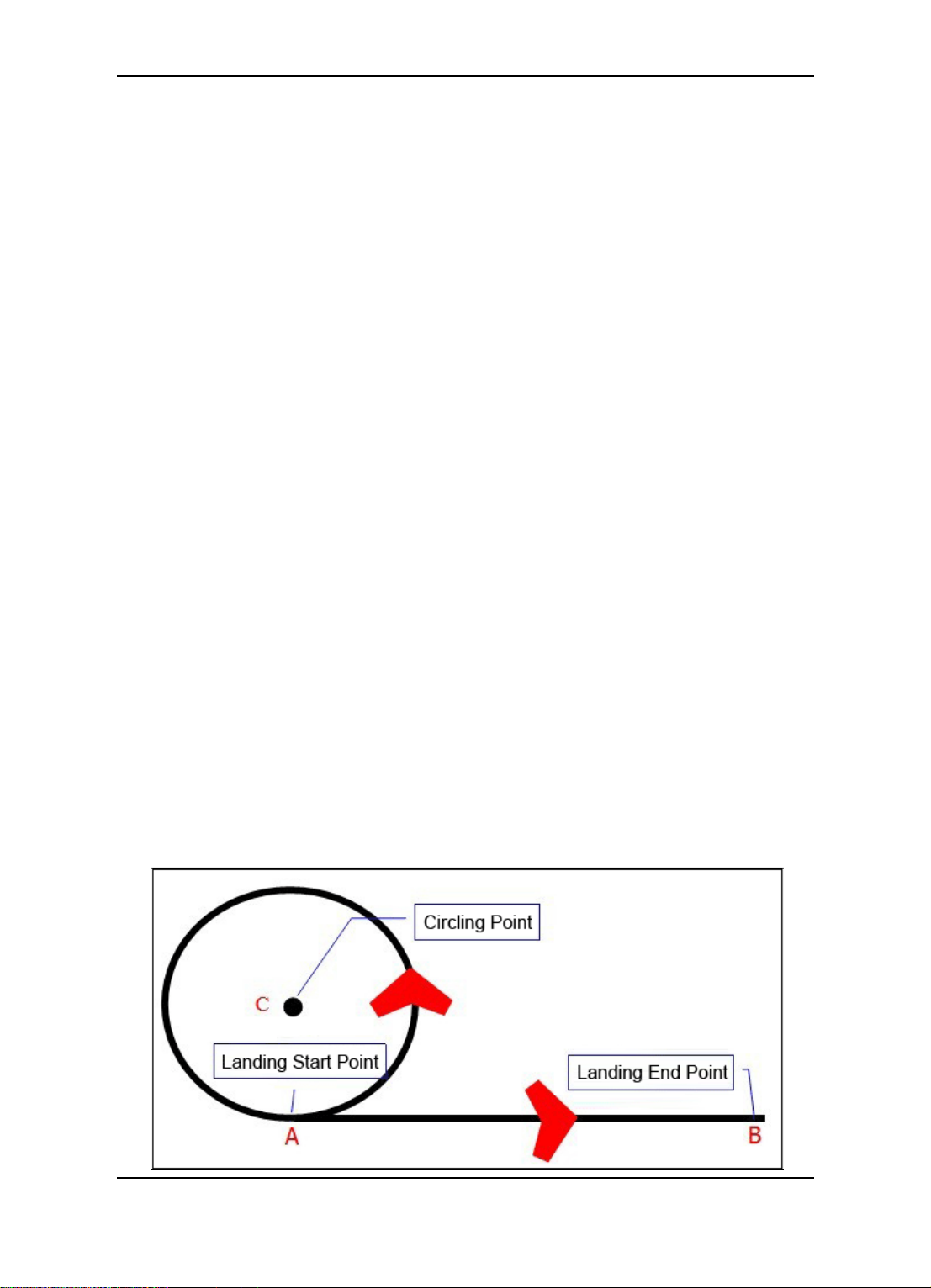
14.4.2 Automatic Landing Achieving
In order to achieve the auto landing, the aircraft need two points to confirm the
landing route: Landing start point and Landing end point. PandaⅡ autopilot will generate
the landing route according to this two point. Refer to the picture, landing start point ―A‖,
landing end point ―B‖, landing route ―A->B‖, distance of ―A‖ and ―B‖ suggest set up more
than 5 meters.
Steps of Automatic Landing Achieving
Step A: Click on ―A Land‖ button on the GCS, the aircraft will fly to circling point ―C‖.
Step B: The aircraft descent to the suitable altitude for entering to the landing route
while circling. LINEAR Landing Mode: Altitude descent to 40 meters; PARACHUTE
Landing Mode: Altitude descent to the parameter which you set via ―OpenP Alt‖ on the
GCS.
Step C: The aircraft enter to the Landing route ―A->B‖ after descent to the target
altitude.
Step D: The autopilot will control the aircraft landed at point‖ B‖, and cut down the
throttle before landing.
LINEAR Landing Mode:The throttle will be cut down when the aircraft descent to
the altitude which less than 12meters;
PARACHUTE Landing Mode: The throttle will be cut down when the aircraft arrive
at a suitable distance before landing end point ―B‖, then shoot out parachute for landing.
Step E: Aircraft landing, the process of the automatic landing finish.
The aircraft land to the ground, the autopilot will switch to “RC”
working mode automatically and keep the throttle cut down.
Automatic landing need for a range of open space. And the auto landing
mode is suitable for small and throwing UAV. Maybe it is possible to
damage the plane ,please used with caution.
Guilin Feiyu Electronic Technology Co., Ltd http://www.feiyu-tech.com service@feiyu-tech.com
Page 35

Guilin Feiyu Electronic Technology Co., Ltd.
14.4.3 Automatic Landing Point Setting
There are three option for landing point setting .The landing point can set up in 2D
view or 3D view on the GCS. Introduce the setting in 2D view as a reference, setting in
3D view please refer to the manual of the GCS.
Click on the ―Land Start‖ or ―Land End‖ button in page ―Route‖ in the parameter
setting bar. Select the setting mode in the pop up setting dialog.
① Set the current point to the target point:
Wait for the GPS positioning well, then take the
aircraft to the point of landing route, click the ―Land
Start ‖ button, select the ―Set the current point to the
target point‖ in the setting dialog then click the ―OK‖
button to set the current point as the landing starting
point ― ‖. Take the aircraft to the ending point
of landing route, click the ‖ Land End ‖ button, select
the ―Set the current point to the target point‖ in the
selection dialog then click on ―OK‖ button to set the
current position as the landing ending point ― ‖.
② Set the target point on the map : In this setting mode, fine the target point then
mouse click on the map to set the landing start point or landing end point. Right click the
mouse to exit the setting landing point mode.
③ Enter the coordinates of the point : In this setting mode, enter the latitude and
longitude of the target point then click the ― OK ‖ button, the landing starting point or
landing end point will be mark on the map. Unit of the latitude and longitude is degree,
input in decimal format.
For Example: setting a landing start point at east longitude:110.283, northern
latitude:25.277 (According to the international standard: the west longitude, south
latitude expressed by negative value)
Click on ‖ Land Start ‖select the‖ Enter the coordinates of the point‖, enter :
Guilin Feiyu Electronic Technology Co., Ltd http://www.feiyu-tech.com service@feiyu-tech.com
Page 36

Guilin Feiyu Electronic Technology Co., Ltd.
110.283 in the longitude edit box,25.277 in the latitude edit box, click on ‖ OK ‖ button, it
will mark the landing starting point at the target coordinates on the map, show as the
following interface.
(Landing ending point please refer to the operation of the setting for landing starting
point.)
14.5 RC Switch (SW2) Setting
Sw2, the three position switch which control navigation working modes can
configurate via the GCS software.‖Menu‖——―Autopilot setting‖——―RC Setting‖ click on
―READ‖ button to get the curren setting and aselect the mode which you want, then click
on ―SET‖ button to confirm the setting.The navigation mode configuration can be check
via the state of the LED on PandaⅡmodule,or check on the GCS after the GPS
positioning well.
After finish the configuration, please click the ”Save” button in page” Param1”
in the tool bar to save the setting.
Guilin Feiyu Electronic Technology Co., Ltd http://www.feiyu-tech.com service@feiyu-tech.com
Page 37

Guilin Feiyu Electronic Technology Co., Ltd.
14.6 Record Servo Neutral
Adjust the center of gravity of the aircraft well, fix the devices on the aircraft, then the
neutral can be record after place the aircraft in correct attitude (The adjustment of COG
of the aircraft we will use fly wing X8 as a reference, please refer to the Appendix B).
Neutral Servo is the reference value of the autopilot when work in the navigation
working mode. The servo neutral must be record in correct attitude.
Servo neutral record: Keep the plane static, leveling the rudder surface, keep the
aircraft level in roll, and a tiny pitching angle in the pitch direction, switch to the ―RC‖
working mode, click on ―Record Servo Neutral‖ button in page ―Param2‖, then go to page
―Param1‖ click ―Save‖ button to save the value.
If the center of gravity of the aircraft , the installation of the PandaⅡ autopilot
without any changing , and the servo neutral don’t need record again after
save with correct altitude.
14.7 POS Information Reading
PandaⅡ has already built-in POS information record module, the POS information
record module has 4M storage space, it will automatically record photo-taken POS
information after the GPS positioning . If the storage space is full, the new POS
information will override the earliest generated files.
POS information can be read out via two connection style: Reading via data radio
connection; Reading via USB cable connect to Panda Ⅱ directly ,this is the
recommended mode.
Guilin Feiyu Electronic Technology Co., Ltd http://www.feiyu-tech.com service@feiyu-tech.com
Page 38

Guilin Feiyu Electronic Technology Co., Ltd.
Please read the POS information after the aircraft landing on the ground. The
reading command will be invalid if the aircraft still in flying;
When reading the POS information the PandaⅡwill enter the “RC” working
mode automatically and keep the throttle shut down;
If POS information reading via data radio, the data radio will be interrupt and
will display the message on the GCS “Data Radio Failure”;
POS information reading diagram ( Operation steps please refer to the
Appendix F):
15. Route Planning
GCS 5.20 or above version support route planning in 2D view and 3D view. Both
operation steps will be introduce.
15.1 Route Planning In 2D View
Load the map to the GCS software, turn to page ―Route‖ in tool bar .
Guilin Feiyu Electronic Technology Co., Ltd http://www.feiyu-tech.com service@feiyu-tech.com
Page 39

Guilin Feiyu Electronic Technology Co., Ltd.
Another way to modify the
information of the waypoint:
Double click the information
to select the waypoint, and
then click the target position
on the map.
If you want to modify the
data, firstly, select the
information of the waypoint,
then edit the information in
this edit box. You can add
or delete the waypoint.
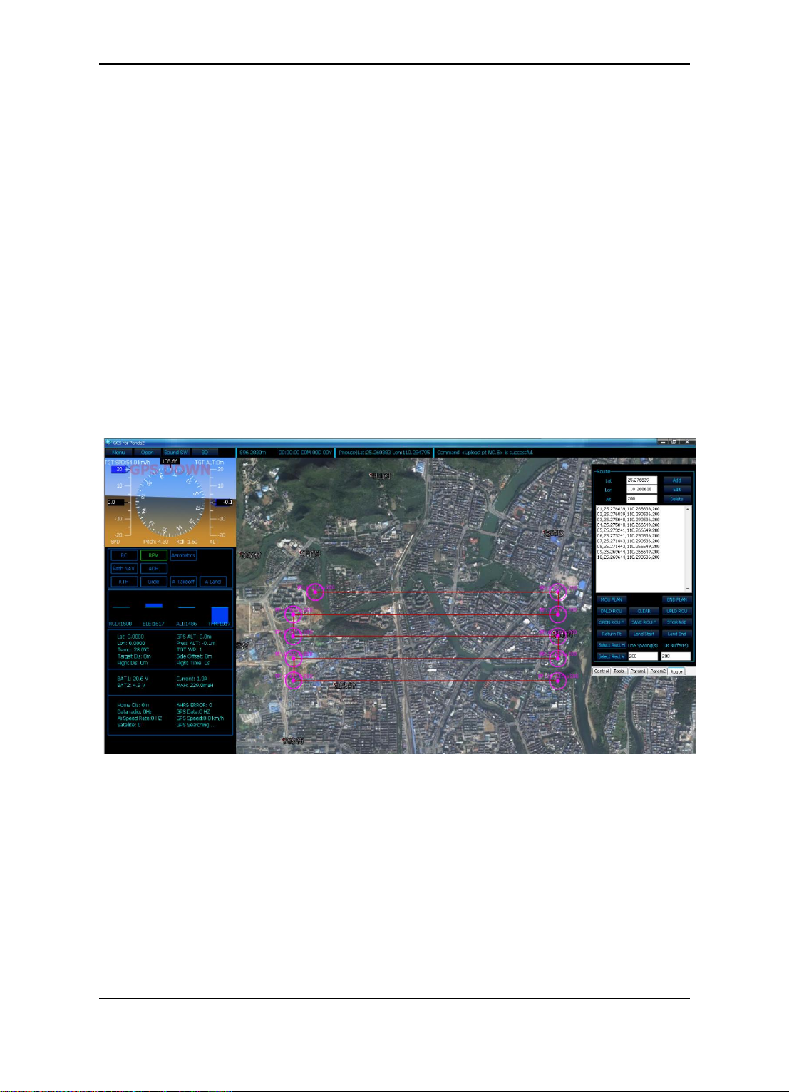
15.1.1 Route Planning By Mouse Click
Click ― MOU PLAN ‖ button, mouse click the target point on the map the waypoint will
generate . Right click the mouse or click the ―END PLAN‖ button to end the route
planning.
Figure Route Planning Interface
After end the route planning, please click ―UPLOD ROU‖ to upload the route to the
autopilot.The pop up dialog box prompt that the route upload finish.
After uploading, clear the current waypoints on the map via click the ―CLEAR‖ button.
And then click ―DNLD ROU‖ to download the information of waypoints from autopilot,
check whether waypoints are correct. Click ―STORAGE‖ button, save the route which is
Guilin Feiyu Electronic Technology Co., Ltd http://www.feiyu-tech.com service@feiyu-tech.com
Page 40
Guilin Feiyu Electronic Technology Co., Ltd.
upload into autopilot, otherwise waypoints will be lost after power outage.
Please don’t click any other buttons when the route is in the uploading
or downloading status.
15.1.2 Regional Auto Route Planning
Firstly, set up the ―Line Spacing‖, ―Distance Buffer‖, then select the route direction
(Horizontal please select the ―Select Rect H‖ button, vertical please select the ―Select
Rect V ‖ button). For example, enter 200 meters in the ―Line Spacing‖ edit box and the
―Distance Buffer‖, click the ―Select Rect H ‖, drag left mouse button to select the region
for route planning, the regional route planning interface show as the following. Click
―STORAGE ‖, save the route which is upload into autopilot, otherwise information of the
waypoints will be lost after power outage.
15.2 Route Planning In 3D View
Please ensure that the network is available, start the GCS software and switch to the
3D interface. If the computer have install the Google Earth plug-in, the 3D view will be
display as the picture.
Guilin Feiyu Electronic Technology Co., Ltd http://www.feiyu-tech.com service@feiyu-tech.com
Page 41

Guilin Feiyu Electronic Technology Co., Ltd.
Route planning in 3D view need to make altitude initialization, use to extracting the
initial relative altitude of the routes in Google earth, otherwise the route may be obscured
under layer.
If the autopilot system connect to the GCS, after GPS fixed position the software
will initialize the altitude automatically. Otherwise you have to manual initialize.
15.2.1 Route Planning In 3D View
Find the needed region, click on the "Path" button in the menu bar to get the route
planning interface.Click on the ―Init Alt‖ button, select ― Y ‖ button in the promt dialog, the
mouse change into gripper type, press on the ―Alt‖ button on the keyboard mouse click
the target point , it will pop-up a dialog box then click the ―Confirm‖ button to finish the
altitude initialization. If you need to reset the initial point, please repeat the above steps.
Guilin Feiyu Electronic Technology Co., Ltd http://www.feiyu-tech.com service@feiyu-tech.com
Page 42

Guilin Feiyu Electronic Technology Co., Ltd.
15.2.2 Regional Auto Route Planning In 3D
After initialized altitude .Input the route altitude, spacing, turn distance in parameter
edit box, click on ―Set‖ button to confirm the setting. Click on the ―Area Start‖ button
mouse change into gripper type, press on ―Ctrl‖ button on the keyboard, select three
vertices of the target area on the map, the fourth vertex of the area will
generated automatically. Show in the following picture (It will display the total area in the
area, for example:1.221sq.km).
Figure Diagram Of The Area
Loosen the "Ctrl" button, click on the ―Area End‖ button, it will generate aerial routes
in the area automatically, shown in picture (It will display the total distance in the area, for
example: 11.591 km). If connected to autopilot system which the GPS have not fixed
position, area route planning will generate the route starting point and ending point at the
center of the area, for example the point 1 and the point 12. If connected to autopilot
system which the GPS have fixed position, area route planning will generate the route
starting point and ending point at current position of the aircraft.
Guilin Feiyu Electronic Technology Co., Ltd http://www.feiyu-tech.com service@feiyu-tech.com
Page 43

Guilin Feiyu Electronic Technology Co., Ltd.
Figure Aerial Route Planning Interface
After route planning completely, please click ―Upload‖ button to upload the route to
the autopilot. After upload the route successfully, it will pop up the following dialog box,
click ― OK ‖ button to confirm.
In order to ensure the waypoint upload with correct information, after uploading,
please clear the current information on the map via click the ―Clear‖ button. And then
click ―Download‖ button to download waypoints from autopilot, check whether
information of the waypoints are correct. After confirm the information of the waypoints,
please turn to ―Route‖ page in the tool bar , click the ―STORAGE‖ button to save the
route which is upload into autopilot, otherwise data of the route will be lost after power
outage.
Please don’t click any other buttons when the air route is in the
uploading or downloading status.
Guilin Feiyu Electronic Technology Co., Ltd http://www.feiyu-tech.com service@feiyu-tech.com
Page 44

Guilin Feiyu Electronic Technology Co., Ltd.
15.2.3 Route Planning By Mouse Click In 3D View
After initialized altitude. Input the altitude in parameter edit box, click on ―Set‖ button
to confirm the setting. Click on the ‖Start‖ button, the mouse change into gripper type,
press on the ―Ctrl‖ button on the keyboard, mouse click on the target point on the map to
set the corresponding navigation point. Loosen the "Ctrl" button, click on the ―End‖ button
to finish route planning (It will display the distance of each route and the total distance ).
The checking of the information please refer to the method which introduce in the
“Regional Auto Route Planning”. After checked, please save the information of the
route in page ―Route‖ in the tool bar, otherwise information of the ruto will be lost after
power outage.
16. Checking And Suggestion For Fly
Step A: Check whether the connection of the aircraft is normal, whether the antenna
place well (If fly for photograph, please check the camera carefully ,whether the
power is enough, whether the storage card is clear and the parameters are
setting normally).
Step B: Check the center of the gravity of the aircraft and the batteries. If the power of
Guilin Feiyu Electronic Technology Co., Ltd http://www.feiyu-tech.com service@feiyu-tech.com
Page 45

Guilin Feiyu Electronic Technology Co., Ltd.
the batteries is normal please clamp the batteries after confirm the center of the
gravity.
Step C: Power on the system for checking on the ground.
1) Turn on the RC transmitter, check the power and the flight mode (Select the
traditional layout of fixed wing flight mode).
2) Start the computer, run the GCS software, power on the part of the autopilot system
on the ground.
3) Power on the aircraft, autopilot system connect to the GCS software successfully
then load the map of flying area.
4) Check the RC setting of the SW2. Wait for GPS positioning, switch the
3-position-switch and check whether the GCS can display the corresponding
working mode.
Step D: Check the flight parameters
1) Set up correct mixing mode, and check the installation direction of the autopilot with
its setting.
2) Switch to ―RC‖ working mode, check whether the control surfaces are smooth then
control the control surface by RC unit, if the direction of the control surface not follow
the direction of the rocker please set up servos reverse on the RC transmitter;
Switch to ―ABM‖ working mode, check whether the automatic control quantity of
servos is correct, if not, please set up reverse on GCS.
3) Check the landing mode and the auto photo mode whether camera can photograph
normally. (Please check the parachute equipment if choose the Parachute landing
mode).
4) Check the target speed and circle radius whether they are matching(Pay attention to
the take-off angle and take-off throttle if choose automatic take off).
Steps E: Initialize the sensors, test and record the servo neutral
1) Airspeed sensor initialization: Keep the aircraft static, cover your hand in front of the
airspeed sensor, then click on ―Initialize the airspeed‖, wait for the value of the
airspeed sensor close to ―0‖, then blow to check whether the airspeed sensor is
working normal.
2) Barometer checking: After finish the initialization of the airspeed, the pressure
altitude will reset to ―0‖. Uplift the aircraft, the altitude will change.
3) Gyroscope initialization: Keep the aircraft static, click on ―Initialize the gyro ‖. Please
Initialize gyroscope before every take off.
4) Record servo neutral: Please refer to the “14.6 Record Servo Neutral” the way
see the manual (attention: If the center of gravity of the aircraft , the installation of
Guilin Feiyu Electronic Technology Co., Ltd http://www.feiyu-tech.com service@feiyu-tech.com
Page 46

Guilin Feiyu Electronic Technology Co., Ltd.
the PandaⅡ autopilot without any changing, and the servo neutral don‘t need
record again after save with correct altitude).
After finish the parameter checking and change, please click the “ Save ”
button in page ” Param1” in the tool bar to save the setting.
Step F: Air route planning and the landing point setting
1) Make sure the air route within the flying range (the first fly please set up a simple air
route for testing).
2) Pick up the landing start point and end point, please refer to the ”14.4.3 Automatic
Landing Point Setting”.
Step G: Power equipment testing
Raise the throttle slowly, check the rotation direction of the motor and force of the
aircraft, whether the brake function is normal.
Steps H: Take off
1) Automatic take off: Please select ―A Take off‖ under ABM working mode.(Don‘t
suggest to use automatic take off at the first flying ), you can assist automatic take
off by RC sticks except throttle.
2) Manually take off: Take off under ABM working mode, slowly reduce the throttle to
the appropriate control after climbing to the suitable altitude.
Steps I: Fly
1) Debugging the aircraft under ABM working mode, check the reaction of the aircraft is
too soft or oscillation, then adjust the parameter according to the actual flying
attitude.
2) Aircraft climbed to suitable altitude (about 100 meters), then switch to ―RTH‖ working
mode. Observe whether the airspeed and throttle control are normal after the aircraft
circling above the home point.
3) Make sure the aircraft can work normally, set up the target altitude to make the
aircraft flight to the working altitude.
4) Switch to the ―Path Navigation ‖ mode, start ―Auto Photo‖.
5) Finish the route flight, the aircraft will circle flying at the end point of the route and
wait for the next command.
Steps J: Landing
Finish the job flying, switch to ―RTH‖ mode, the aircraft will circle at the home point,
change the target altitude on the GCS to make the aircraft descent to the suitable altitude
(about 100 meters), then landing.
Guilin Feiyu Electronic Technology Co., Ltd http://www.feiyu-tech.com service@feiyu-tech.com
Page 47

Guilin Feiyu Electronic Technology Co., Ltd.
Step K: The Post processing
1) Power off the aircraft after landing, turn off the RC unit and GCS, take back the
aircraft.
2) Read the image from the camera, the POS information from the PandaⅡ autopilot,
then post processing.
Appendix
Appendix A: Introduction For Other Functions And
Settings
1. “Click Point Flight” Working Mode
PandaⅡ autopilot can enter the ―Click Point Flight‖ mode under any working mode.
Click on the ―Set ClickP‖ button in page ―Control‖ in tool bar on the GCS, then click the
flight target point on the map, the aircraft will fly to the target point directly with the current
altitude then hovering and waiting for the next command. Click the ―Cancel‖ button in
page ―Control‖ on GCS to exit the ―Click Point Flight‖ mode or you can switch the SW2 to
any navigation mode to exit.
2. Route Loop Function
The default path navigation working mode is not circulation, the aircraft will hovering
at the last waypoint and waiting for the next command when the aircraft finish the route
flying. Click on the ―Not Loop‖ button in page ―Control‖ on the GCS to cancel the the
default setting .The button will display ―Loop‖ after change the setting. If the ― Path
Navigation‖ fly with ―Loop‖ the aircraft will auto repeat the waypoint. When the aircraft
fly over the last waypoint it will back to the first waypoint for lying again.
After finish the parameter setting, please click the “Save” button in page
“Param1” in the tool bar to save the setting.
Guilin Feiyu Electronic Technology Co., Ltd http://www.feiyu-tech.com service@feiyu-tech.com
Page 48

Guilin Feiyu Electronic Technology Co., Ltd.
3. Special Instruction For Navigation Working Mode
The aircraft can not be control by Remote Control when work in navigation mode
except Fixed altitude & Heading lock Mode.
The aircraft can be control by Remote Control when work in Fixed altitude & Heading
lock Mode except the throttle.
When working in navigation mode, once the flight altitude descend to less than 12
meters, the throttle will shut down.
4. Auto Waypoint Photograph Setting
The ―Auto Take Photo Waypoint‖ function
can be set up in page ―Param2‖in the tool bar on
GCS.
The autopilot will activate the ―Auto Photo‖
when the aircraft arrive the start waypoint, and
turn off the ― Auto Photo‖ when arrive the end
waypoint in the Path Navigation working mode.
For example: Parameters set as―Start‖: 2,―End‖: 4, the auto take photo function will
be activate at the waypoint which is number 2 and turn off at the waypoint which is
number 4.
When the starting and the ending point set as “0”,it means that disable the
function of “Set Auto Take Photo Waypoint”.
After finish the parameter setting, please click the “Save” button in page
“Param1” in the tool bar to save the setting.
5. Set Up Target Waypoints
( 1 ) Significance Of Setting Target Waypoint
Working in the path navigation mode. When the autopilot receive the command
about the setting target waypoint, the aircraft will fly immediately to the target waypoint
from the current position then execute the new routes (The new route start from target
waypoint to the ending waypoint) .
Guilin Feiyu Electronic Technology Co., Ltd http://www.feiyu-tech.com service@feiyu-tech.com
Page 49

Guilin Feiyu Electronic Technology Co., Ltd.
If the target waypoint setting when the aircraft work in other working mode (not in
the path navigation mode),the air routes will start from the target waypoint when switch
to the path navigation mode.
( 2 ) Operation Of Setting Target Waypoint
Click on “SET POINT” button in page “Route”
in the tool bar on GCS. Input the waypoint number in
the setting box(For example:3), click on ― OK ‖ button
to confirm then setting, the command will send to the
autopilot immediately.
Please input the number which within the effectively waypoint number.
6. Throttle Setting
Pnada2 autopilot can limit the range of the throttle. This function commonly
used in most of the gasoline engine and some special motor.
Operation For Throttle Setting: “Menu”—“Autopilot Setting”—“Throttle Setting”
(1) Set up the lower and upper limit of the throttle lever on the remote control.
(2) Connect the autopilot to the GCS software. Put the throttle lever to the lowest
position on the remote control, click the ―Minimum Throttle‖ to record the throttle lower
limit; Put the throttle lever to the highest position on the remote control, click the
―Maximum Throttle‖ to record the throttle upper limit.
Please remove the motor before record the maximum throttle, to avoid the
harm cause by the motor rotation.
After finish the throttle setting, please click the “ Save ” button in” Param1”
page in the tool bar to save the setting.
Guilin Feiyu Electronic Technology Co., Ltd http://www.feiyu-tech.com service@feiyu-tech.com
Page 50

Guilin Feiyu Electronic Technology Co., Ltd.
7. Up/Down Data Frequency
"Teleme Rate" Refers to the autopilot data downlink frequency. Because the limit of the
data radio performance, please set up the "Teleme Rate" to 1HZ.
"RC Rate" means the remote control frequency when using the Remote Adaptor.
Because the limit of the data radio performance, please set up the "RC Rate" to 10 HZ. If
the frequency is set too high, it will obstruct the communication of the data radio and can
not communicate at all.
After finish the throttle setting, please click the “ Save ” button in” Param1”
page in the tool bar to save the setting.
8. Connection Option And Control Mode Setting
If the PandaⅡ autopilot system connection in accordance with the ―OPTION 1
(“RC” control mode )” please set up the control mode as ―RC‖ through GCS software. If
connection in accordance with the ―OPTION 2 (“DRRC” control mode )” please set up
the control mode as ―RC‖ through GCS software.
After finish the control mode setting, please click the “ Save ” button in”
Guilin Feiyu Electronic Technology Co., Ltd http://www.feiyu-tech.com service@feiyu-tech.com
Page 51

Guilin Feiyu Electronic Technology Co., Ltd.
Param1” page in the tool bar to save the setting.
Appendix B: Adjust The Center Of Gravity
Lift the aircraft at the design COG (center of gravity) point. It is OK if the aircraft can
satisfy the conditions: maintain balance at rolling and the head or tail slowly title to one
side. Please fix the batteries and the other equipment well after finish the adjustment.
Appendix C: Flight Area Map Making
( 1 ) Confirm the network is available, start the GCS software, click the ―3D‖ button on
the GCS switch to 3D view. Hidden the toolbar, make the GCS software to maximize
window.
( 2 ) Set up the screenshot resolution before making map. The default setting is ―High‖.
Suggest that use the default setting.
( 3 ) Selecting region for screenshot.
Fine the desired region on Google earth, press the “Alt” on the keyboard, mouse
will change into gripper type, click the first and the last point of the region, the GCS
software will generate the screenshot region automatically.
Guilin Feiyu Electronic Technology Co., Ltd http://www.feiyu-tech.com service@feiyu-tech.com
Page 52

( 4 ) Map making
Guilin Feiyu Electronic Technology Co., Ltd.
Click the “Make Map” button to grab the map after select the region. In the
process of grabbing the map, you can’t do any operation, click and move the mouse is
also forbid, wait for finish grabbing the map.
In the process of map making, the total number of the pictures, the serial number of
the pictures which is grabbing at present will display in the message bar.
Guilin Feiyu Electronic Technology Co., Ltd http://www.feiyu-tech.com service@feiyu-tech.com
Page 53

Guilin Feiyu Electronic Technology Co., Ltd.
( 5 ) Finish grabbing the pictures, it will pop-up a dialog box to prompt
that getting picture is OK. Click ―Confirm‖ button, choose the save
path in the save dialog box, the file can be rename, but please don‘t
change the file format. Click the ―Save‖ button to finish making map.
Guilin Feiyu Electronic Technology Co., Ltd http://www.feiyu-tech.com service@feiyu-tech.com
Page 54

Guilin Feiyu Electronic Technology Co., Ltd.
Map making success should be generate 3 format files with the same name,
( “.gst”, “.tab”, “.jpeg” files). The .gst file is the map file that load in the 2D
view on the GCS, after load it can do route planning or other operations.
The region have selected too large or too small may cause failure of the map
making. Total number of the pictures should be less than 512 pictures.
The screenshot resolution of the map making about the GCS is “Height”, In
the same conditions, the higher the resolution, the clearer map which make in
3D view.
Appendix D: Voltage Calibration Operation
( 1 ) Measure the actual voltage of the batteries, record as:V0.
( 2 ) Connect the batteries to the power manager,the voltage display on the
GCS(BAT1) record as V1 .
Formula for voltage calibration ratio:C=(V0 / V1) x 100
For example: Actual voltage of the batteries V0 =15.76 V ;
Voltage display on the GCS V1=15.5 V
Voltage Ratio C=(15.74/15.5) x 100=1.017*100=102
Settings of voltage calibration: ―Menu‖——― Autopilot setting ‖—— ―Power Voltage
Calibration ‖, it will pop-up the setting dialog.
“Voltage Ratio”= “0” means that the voltage display without calibration. If the
voltage is need to be correct, please calculate the voltage ratio "C".
According to the above steps,then enter into the dialog , click on“OK”button to
confirm the setting of this parameter (For example: 102).
Guilin Feiyu Electronic Technology Co., Ltd http://www.feiyu-tech.com service@feiyu-tech.com
Page 55

Guilin Feiyu Electronic Technology Co., Ltd.
After finish the voltage calibration, please click on ―Save‖ button in page ―Para1‖ to
save the setting to the autopilot, otherwise the autopilot will restore the original settings
after power off.
( 3 ) After the voltage calibration success, the voltage display on the GCS(―BAT1‖) is
the power voltage which have been calibrated .
Voltage can be calibrate through USB cable connect to the autopilot directly or
calibrate through the data radio.
Appendix E: Airspeed Sensor Installation And Calibration
( 1 ) Airspeed Sensor suggest that install as the figure: The airspeed sensor needs to
pull ahead the front of the pneumatic opening and in the line with the direction of flight.
The tail end of the sensor cannot be blocked. The Airspeed sensor can be install on the
wing or in the front of the nose, please make sure the body of the aircraft does not affect
the air inlet.
Guilin Feiyu Electronic Technology Co., Ltd http://www.feiyu-tech.com service@feiyu-tech.com
Page 56

Guilin Feiyu Electronic Technology Co., Ltd.
( 2 ) Airspeed Sensor calibration: Suggest that calibration in the windless flight
environment.
Take off after Airspeed Sensor initialization. Keep the aircraft level flight, observe the
current airspeed and the GPS speed try to calibrate both to uniform (Also suggest that
the airspeed less than GPS speed 5~10KM).
The calibration operation: If the current airspeed larger than the GPS speed please
reduce the airspeed parameter——―ASP‖ in page ―Param1‖ on tool bar, otherwise
increasing the ―ASP‖ then click on the ―Set‖ button to confirm the modify. Check again, if
the current airspeed is normally to the desired value please click on "Save" button in
page ―Param1‖ on the tool bar to save the parameter.
Appendix F: POS Data Reading And Instructions
1. Steps for POS data reading
1) Establish the connection between PandaⅡ autopilot and the GCS software.
2) Select ―Menu‖ –―Read Pos Data‖, it will load the POS information read dialog box.
3) Click the ―Read File List ‖ the file will display in sequence.
4) Select the file you want click ―Read File‖ button, then the information box will display
the content of the file.
5) Click ―Save File‖ button, the selection file will be saved to the computer. Select the
desired saving path, input the file name in the Pop-Up dialog (Please added the .txt
expanded-name).
Guilin Feiyu Electronic Technology Co., Ltd http://www.feiyu-tech.com service@feiyu-tech.com
Page 57

Guilin Feiyu Electronic Technology Co., Ltd.
If need for other POS data file please follow the above steps.
2. POS Data Instructions
1) The file name according to date and time of the current GPS data: year-month-day,
hour-minute-second. The sequence number will + 1 after record a new file.
2) Open .txt document, every data is separated by ―,‖ and a line of data is created in
every photo-taken.
Guilin Feiyu Electronic Technology Co., Ltd http://www.feiyu-tech.com service@feiyu-tech.com
Page 58

Guilin Feiyu Electronic Technology Co., Ltd.
Type of command
Pos information
Fields 1
Photo serial No.
Fields 2
Time of photo taken(hour)
Fields 3
Time of photo taken(Minute)
Fields 4
Time of photo taken(Second)
Fields 5
latitude
Fields 6
longitude
Fields 7
GPS Height above sea level
Fields 8
pressure altitude
Fields 9
Flight speed(Km/H)
Fields 10
Pitch angle (unit degree)
Fields 11
Roll angle (unit degree)
Fields 12
Heading angle (unit degree)
Fields 13
Aircraft head heading angle (unit degree)
Instructions Of Every Data
Appendix G: Modify The COM Port Number
( 1 ) After correct install the USB driver ,insert the USB cable to the computer, open the
"Device Manager".
Guilin Feiyu Electronic Technology Co., Ltd http://www.feiyu-tech.com service@feiyu-tech.com
Page 59

Guilin Feiyu Electronic Technology Co., Ltd.
( 2 ) Right click【Ports: Silicon Labs CP210x USB to UART Bridge(COM**)】, select
"Properties‖.
( 3 ) Switch to the "Port Setting" then click "Advanced (A)" button.
Guilin Feiyu Electronic Technology Co., Ltd http://www.feiyu-tech.com service@feiyu-tech.com
Page 60

Guilin Feiyu Electronic Technology Co., Ltd.
( 4 ) In the settings window click on the COM number, please select the available COM
number which within COM10 (For example COM3) and then click "Confirm" button
to confirm the setting.
( 5 ) Check in the ―Device Manager‖ again , and the port number will change to COM3.
Guilin Feiyu Electronic Technology Co., Ltd http://www.feiyu-tech.com service@feiyu-tech.com
Page 61

Guilin Feiyu Electronic Technology Co., Ltd.
Appendix H: Run The GCS As Administrator
Appendix J: Fail Save Instructions
Setting Home Point
After power on the autopilot system, the point where the GPS position first time will
be record as home point automatically. The home point can be reset by click on the
―Return Pt‖ button in page "Route" in the toolbar. Click the ―Return Pt‖ button, then left
click mouse on the map, the point will be record as the new home point.
“Fail-Safe” Of The RC And Auto Return To Home
Equipments of the autopilot system connection by ―OPTION1 (―RC‖ control mode)‖.
RC receiver connect to the PandaⅡ directly, both of RC transmitter and RC receiver
must be ―Fail-Safe‖ function. The SW2 should be switch to the RTL (Return to Launch)
working mode when set up fail save in the‖ Fail Save‖ menu on the RC transmitter.
Data Radio Communication Interrupt And Return To Home
Equipments of the autopilot system connection by ―OPTION2 (―DRRC‖ control
Guilin Feiyu Electronic Technology Co., Ltd http://www.feiyu-tech.com service@feiyu-tech.com
Page 62

Guilin Feiyu Electronic Technology Co., Ltd.
mode)‖. RC receiver connect to Remote Adapter, the Panda Ⅱ will detect the
communication automatically when in flying, if the communication is interrupt by 5
seconds continuous, the PandaⅡ autopilot will switch into RTL "Return to Launch "
working mode automatically.
Appendix K: Photograph Caption Of The Camera Refit
The P1 port on the autopilot module is the photograph controlling interface. It can
output a camera shutter triggered signals, this signal is TTL level (0-3V), if you take
photos by small camera like Canon S100V, the camera need to be refit to release the
remote cord then connect to the P1 port ,the camera can be control by PandaⅡ autopilot
now. This pictures will show the refitting of Canon S100V:
Guilin Feiyu Electronic Technology Co., Ltd http://www.feiyu-tech.com service@feiyu-tech.com
Page 63

Guilin Feiyu Electronic Technology Co., Ltd.
On the basis of the original value, increase these 2 parameters
Appendix L: PID Control----“Turn Ctrl” Parameter
Adjustment.
There are three items in one parameter: P、I、D. When the PandaⅡ autopilot work in
"navigation" mode, if the aircraft flight from point A to point B, and when one of the
following situation occurs please modify corresponding settings according to the
instructions below to get a better flying .
Situation 1: The aircraft fly a long "S" way along the line, like the picture below, please
adjust the parameter: "Param1" -> "PID Control" -> "Turn Ctrl" increase the 1st and 3rd
items.
Situation 2: The aiecraft fly a small "S" way along the line, like the picture below,
Guilin Feiyu Electronic Technology Co., Ltd http://www.feiyu-tech.com service@feiyu-tech.com
Page 64

Guilin Feiyu Electronic Technology Co., Ltd.
On the basis of the original value, decrease these 2 parameters
On the basis of the original value, increase this parameter
please adjust the parameter : "Param1" -> "PID Control" -> "Turn Ctrl" , decrease the 1st
and 3rd items, if the situation still exist, please fine tune the 3rd item again, increase first
then tune it smaller until appropriate.
Situation 3: The aircraft always deviate from the center of the line, please adjust the
parameter: "Param1" -> "PID Control" -> "Turn Ctrl", increase the 2rd item.
Situation 4: The aircraft wave along the line (with very small deviation to the center of
the line), please adjust the parameter: "Param1" -> "PID Control" -> "Turn Ctrl",decrease
the 2rd item.
Guilin Feiyu Electronic Technology Co., Ltd http://www.feiyu-tech.com service@feiyu-tech.com
Page 65

Guilin Feiyu Electronic Technology Co., Ltd.
PID Control
Name
Parameter
P I D
Turn Ctrl
60
20
60
Altitude Ctrl
50
10
50
Throttle Ctrl
50
10
50
Head Stability
50
10
50
Pitch Stability
50
20
50
Roll Stability
50
20
50
Flight Parameters
Name
Parameter
Instruction
TGT SPD
68.4 (Km/h)
The expectations speed when work in the navigation
working mode.
TGT ALT
0 (m)
The expectations altitude when work in the navigation
working mode.
CIR RAD
120 (m)
The circling radius when hovering.
On the basis of the original value, decrease this parameter
Appendix M: Default Parameters Of PandaⅡ Autopilot
Guilin Feiyu Electronic Technology Co., Ltd http://www.feiyu-tech.com service@feiyu-tech.com
Page 66

Guilin Feiyu Electronic Technology Co., Ltd.
PhoIntval
4 (S)
The interval of auto photo (Timing-PG).
Cruise thr
50%
Throttle reference quantity when switch to the
navigation working mode.
PG DELAY
1200 (ms)
The interval time between output the camera shutter
and completely save the POS data of the photo
ASP
120
The reference value of the airspeed sensor calibration.
Auto Take Off Parameters
Name
Parameter
Instruction
TakeOff pitch
15°
The minimum climb angle during auto takeoff.
TakeOffThrottle
95%
The maximum throttle quantity for using during
the auto takeoff
Configuration Of Auto Takeoff & Auto Landing Mode
Auto Landing
Line
Note:The default altitude of open parachute is 50
meters when select the ―Parachute‖ Landing
mode .
Auto Takeoff
Hands Throws
Configuration of RC
Remote Control
Setting
Instruction
SW2
Go Home
Note: SW2 have to maintain a NULL
position.
NULL
Path
RC Max Distance
4000 Meters
Note: This function activate when
autopilot system connect as
―OPTION1 (RC control mode)‖
Other Basic Configuration
Control Mode
―DDRC‖ Mode (Note: Matching to the ―OPTION2‖ connection )
Fail Save
Auto Return (Note: Setting only activate when autopilot system connect as
―OPTION2 —— ―DDRC‖ control mode)‖
Mixing Control
Normal (AIL NAV)
Install Setting
Arrow Front
Guilin Feiyu Electronic Technology Co., Ltd http://www.feiyu-tech.com service@feiyu-tech.com
Page 67

Guilin Feiyu Electronic Technology Co., Ltd.
Appendix N: Firmware Upgrade
PandaⅡ autopilot contain the basic function of firmware upgrade, users can update
to the latest firmware which release on the official website: www.feiyu-tech.com.
1. Steps for firmware upgrade
(1) Please visit the official website of Feiyu Tech: www.feiyu-tech.com to download the
latest firmware and the firmware upgrade software and the USB driver.
(2) After successful install the USB driver, please insert the USB data cable to the
computer. Confirm the port number in ―Device Manager‖ on the computer (If the port
number is more than COM10 , please modify to the available number within
COM10 ).
(3) Open the firmware upgrade software, select the right COM port number
(For example COM3), baud rate —— 19200, the correct type of the product ——
FY-Panda2, then click on ―Open ‖ button.
Guilin Feiyu Electronic Technology Co., Ltd http://www.feiyu-tech.com service@feiyu-tech.com
Page 68

Guilin Feiyu Electronic Technology Co., Ltd.
(4) USB data cable connect to the "UART" port on the PandaⅡ. ―Connect OK!‖ will
display in the information bar on the software after connect successfully.
(5) Click the "Read the version number" button to get the information of current
firmware in autopilot, click on "Select the file" button to select the firmware (.Bin
file).
Guilin Feiyu Electronic Technology Co., Ltd http://www.feiyu-tech.com service@feiyu-tech.com
Page 69

Guilin Feiyu Electronic Technology Co., Ltd.
(6) Click the ―Start upgrade‖ button, the progress of upgrade will display in information
bar on the software, waiting for completing the upgrading.
(7) Firmware upgrade success, close the serial port, remove the USB cable.
Guilin Feiyu Electronic Technology Co., Ltd http://www.feiyu-tech.com service@feiyu-tech.com
Page 70

Guilin Feiyu Electronic Technology Co., Ltd.
2. Notes In Upgrading
( 1 ) Please remove all devices before firmware upgrade.
( 2 ) Please operate step by step, and ensure that click ―Open‖ button to open the series
port before the USB data connect to the PandaⅡ.
( 3 ) Please don‘t interrupt the upgrading forcibly.
( 4 ) After completes firmware upgrade. It will fail to get the current information of the
firmware if click the "Read the version number" button directly. Please disconnect then
connect the PandaⅡ again.
This manual is just a guideline to help you set up your aircraft for autonomous flight.
As each aircraft is unique, you will need to fine tune the settings to suit your aircraft‘s
flight characteristics.
–––– END ––––
Note: We reserve the right to change this manual at any time! And the newest edition will
be shown on our website www.feiyu-tech.com.
Guilin Feiyu Electronic Technology Co., Ltd http://www.feiyu-tech.com service@feiyu-tech.com
Page 71
 Loading...