

GuiLin FeiYu Electronic Technology Co., Ltd http://www.feiyudz.cn E-mail: service@feiyu-tech.com
FeiyuTech
FY-21AP Flight Stabilization System
Installation & Operation Manual
Dear Pilot,
Thank you for purchasing the FY-21AP Version II stabilizer from FeiYu Tech.
In order to achieve full potential and safe operation of this product, please carefully read this
manual prior to installation
Warning:
The installation and use of this device require some skill and knowledge in flying remote
controlled fixed wing aircraft.
If you are a complete beginner and have never flown one before, we do not recommend you
install this device on your own.
Please find assistance from an experience flier who may provide you with the basic knowledge
required to use this device successfully.
If you are already an experienced flyer, you will find the installation to be easy and logical. Just
follow the instructions as stated in this manual and you won‟t go wrong.
You may e-mail us directly for assistance; tech@feiyu-tech.com
How It Works
Attitude Flight Stabilization System (AFSS)
FY-21AP Version II is an advance Attitude Flight Stabilization System (AFSS) and Autopilot
for RC aircraft.
The FY-21AP utilizes a 3-axis gyroscope and tri-axial accelerometer to form an accurate drift
free attitude stabilization system. The unit also utilizes Global Positioning System (GPS) and a
barometric altitude sensing for accurate 3-dimensional positioning of the aircraft. By combining
attitude control and positioning, a comprehensive inertial navigation system and autopilot is
provided to you in a small compact light-weight package.
The AFSS achieves its attitude control via FeiYu Tech‟s proprietary algorithm, the unit
calculates the aircraft attitude in 3-dimension and detects any changes to the model‟s horizontal
position. If attitude change occurs, controlling signals will be sent out to the plane‟s ailerons,
elevator and rudder to counter the change. By continuously doing this, the plane is kept in a state of
stabilized equilibrium, resulting in a smooth level flight.
When activated, you only need to release the flight control sticks so that they return to the
transmitter neutral (middle) position. The model will immediately revert to level flight. The unit can
be activated or de-activated via a spare channel from your receiver.
GPS, Barometric Sensing and Autopilot
Upon initial boot up, the FY-21AP will search for GPS positioning signals. When a minimum
of 5 satellites have been detected, a fixed position is established. The FY-21AP will record that
position as the return to launch (RTL) point.
The on-board barometric sensor and GPS altitude readings will be combined to establish an
accurate relative-altitude of the aircraft.
When the Autopilot Mode is activated via a spare channel, the aircraft will automatically turn
and fly back to the take off point (RTL). The aircraft altitude will be constantly maintained. After
reaching the home position, the plane will automatically circle with a radius of 120 meters. By using
the same autopilot algorithm, you can also activate an auto circling flying pattern at a fixed altitude
anywhere you wish.
DEVICE FUNCTIONS
FY-21AP Attitude Flight Stabilization System
Constant stabilized flight in any condition – the FY-21AP will automatically level the flight
attitude of your aircraft in any weather condition. If you are just learning to fly, this will help
you gain experience, log more flying time and increase your confidence. The FY-21AP can be
activated throughout the flight duration, from take off to landing.
Emergency Recovery – in case you lose orientation or you feel the aircraft is out of control,
activate the FY-21AP and let go of the control sticks. The FY-21AP will immediately bring the
plane back to stabilized level flight.
Precision Flying: For the experienced pilot, FY-21AP can help you achieve more leveled and
precise flight paths, especially when flying and landing in strong wind.
First Person View (FPV): For long distance flying or FPV, the FY-21AP will take over the job
of leveling and stabilizing the plane for you. Just point the plane where you want to go and
enjoy the view!
FY-21AP GPS and Barometric Sensor
Fixed altitude flight - When this function is activated, the unit will maintain your aircraft
altitude. You only need to input the right throttle level and point the plane in the direction you
want to go.
Return to Launch (RTL) – You can flip the designated RTL switch on your radio and the
aircraft will return to the take-off point. RTL can also be programmed into your Receiver
failsafe so that the aircraft returns home if RC link is lost.
Fixed Position circling – by activating this function, the aircraft will automatically circle the
selected area at a fixed altitude. Very useful for aerial photography.
Optional Upgrade with FYOSD and 606 Data Radio
The FY-21AP provides an optional upgrade combining the FYOSD with the FY-606 Data
Radio. With this add-on, you will receive:
Real time telemetry – real time by-directional telemetry is monitored directly by your ground station
computer. Changes to aircraft altitude, circle radius and flight path can be controlled from your ground
station computer.
Record and monitor your flight - you can monitor and download your flight path into your ground
station computer.
For more information, please refer to the FY-OSD Version 2.0 and FY-606 manual.
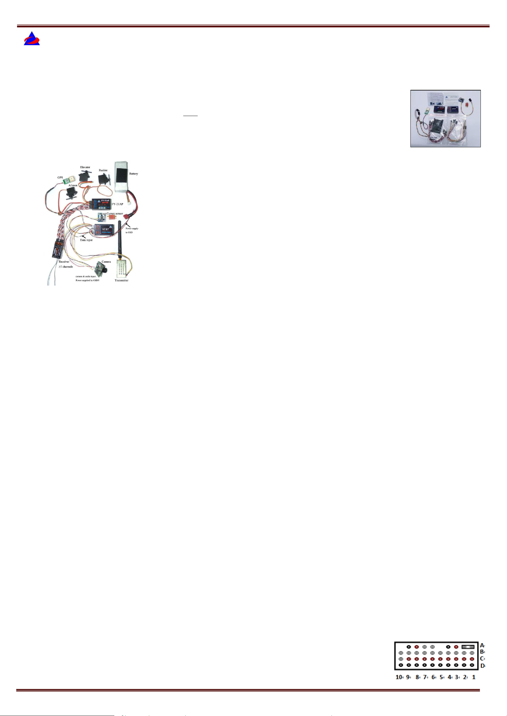
COMPLETE FY-21AP PACKAGE CONTENT
In each set of FY-21AP, you will receive the following:
• 1 x FY-21AP Version II unit
• 6 x RC receiver connecting wires;
• 1 x GPS Receiver;
• 1 x Current Sensor;
• 1 x OSD circuit board;
• 2 x Velcro double sided tape
• 1 x instruction manual;
• 1 x vibration absorbing mount;
• GPS wire with ferrite filter
• Some related wirings
Technical Specification and working requirements:
Working voltage : 4.0~6.0 Volt
Current draw : 52mA (at 5V)
Size : 55 x 33 x 20 mm(2.17 x 1.3 x .79 in)
Weight (exclude wire) : 20g (0.71oz)
Working Temperature : -25°C~ +70°C (-13°F~+150°F)
Maximum rate of rotating : ≤ 1200 °/s
Aircraft Suitability
The FY-21AP has been proven to operate in the following aircrafts:
1. Normal / Traditional fixed-wing planes
2. Delta-winged plane with rudder
3. Delta-winged plane without rudder,
4. Plane without aileron,
5. V –tail plane with aileron
6. V –tail plane without aileron
7. Any other configuration, please e-mail us for enquiry: tech@feiyu-tech.com
Remote Control system requirement:
The FY-21AP has been tested to work with the following RC systems:
Robbe-Futaba PPM / PCM 1024 / PCM G3 mode, 2.4 GHz systems;
Graupner/JR PPM 8, PPM 12, SPCM mode;
MPX PPM8, PPM 12 with UNI mode
Any remote control system using the standard of 1.5 ms neutral position.
FY-21AP Flight Modes
A. The FY-21AP has three flight modes. You may activate any of the flight modes via a free Receiver
channel and a 3-position switch on your computer radio:
MODE 1: Deactivated Mode. In this mode, all control of the aircraft is by the pilot. The FY-
21AP does not participate in flight control.
MODE 2: Stabilized mode. In this mode and your transmitter control sticks at center, the FY-
21AP will continuously send out controlling signal (aileron, elevator, rudder) to ensure the
aircraft maintains a stabilized, horizontal flight and constant flight direction. In this mode FY21AP will not allow acrobatic flights.
Warning: The Auto Balance Mode will provide a smoother leveled landing for your aircraft.
However, note that the turning radius is much larger when AFSS is activated. Please ensure
your landing area has adequate clearance for this larger flight radius.
MODE 3: Fixed–Altitude Flight Mode. In this mode the aircraft Stabilized Mode is activated
combined with fixed altitude flight. Upon activation, the aircraft is immediately stabilized while
altitude is maintained autonomously. You only need to control the direction of the plane.
STALL WARNING: The FY-21 AP has no control over your throttle channel. When flying in
MODE 3, please ensure you have enough forward movement to prevent your aircraft from
stalling. If your forward movement cannot compensate for the autopilot‟s active altitude hold
action, your aircraft will stall.
B. FY-21AP Autonomous Flight Modes
Two autopilot modes are incorporated into the FY-21AP algorithm:
AUTOPILOT MODE 1: Deactivated. The autopilot function is not activated.
AUTOPILOT MODE 2: Auto Return to Launch (RTL). When activated in this mode, the FY-
21AP will automatically fly the plane to the take-off point, while maintaining altitude. Upon
reaching the launch area, the unit will automatically fly the plane in a circle at a default circling
radius of 120 meters.
Note: Should you change the Autopilot Mode during lost of RC signal, the RTL Mode will
immediately change to this latest mode upon RC signal re-establisment.
AUTOPILOT MODE 3: Auto circling mode (ACM). When activated in this mode, the plane
will immediately fly in a circle. The centre of the circle is the point of activation. The default
circle radius is 120 meters. The aircraft altitude will be automatically maintained throughout the
ACM.
AUTOPILOT STALL WARNING
a. The FY-21AP has no control over the throttle channel. Therefore when flying in Autopilot Mode,
please ensure you have enough forward movement to prevent stalling.
b. If your forward movement cannot compensate for the autopilot‟s active altitude hold, your aircraft
will stall.
c. This is especially important if RTL is part of your RC failsafe. In the event of RC Link lost, you can
set RTL into your Receiver failsafe. However, please do not forget to also set your throttle failsafe to
between 25 % to 50% to prevent stalling.
d. Never set your throttle failsafe to zero. If you do so, your aircraft will RTL in a continuous stalled
flight which will result in a crash.
Gyroscope initialization (re-setting):
Out of the box, the FY-21AP has been fully initialized. However, if the following conditions occur,
initialization is recommended:
1. The device has not been used for a long time.
2. There is a change in environmental temperature of
over 30 degrees since last flight.
3. When in Mode 2: Stabilized Mode, and the
installed device in the horizontal position, the plane
control surfaces begin to move and deflect by itself,
without input from the pilot.
GuiLin FeiYu Electronic Technology Co., Ltd http://www.feiyudz.cn E-mail: service@feiyu-tech.com page 1
GuiLin FeiYu Electronic Technology Co., Ltd http://www.feiyudz.cn E-mail: service@feiyu-tech.com
Flight
mode
MODE 1:
Stabilization
not active
MODE 2:
Stabilization
active
Autopilot Mode
3: (circling mode)
Autopilot
Mode 2:
RTL
MODE 3:
FixedAltitude
Flight
Red LED
light
indicator
Continuous
uniform
flashing
Stay ON
solid
Continuous, single
flash each loop
Continuous,
double flash
each loop
Continuous
flashing.
3 times each
loop
Status
Too much vibration
(flight stabilization
will not function)
No GPS
GPS data
received
GPS location fixed
(> 5 satelites)
Blue LED
light
Indicator
Stay ON solid
Stay OFF
solid
Continuous
Single flash each
loop
Continuous double flash
each loop
Red LED
Blue LED
Initialization / Reset Process
Install the jumper as shown in this picture:
Power-ON the FY-21AP and keep it stationary for at least 20 seconds. You will notice the red light
blink with two different rates.
After 20 seconds the re-setting / initialization is complete. Disconnect the power, unplug the
jumper & remove it (keep safe for future use).
NOTE: Carry out this re-setting procedure only if the above occur. We do not recommend
regular re-setting. It is not necessary and not recommended.
The stabilizer unit does not need to be in a horizontal position during initialization. However, you
must ensure there is no vibration during this process. If you suspect shaking occurred, just restart
the initialization / resetting process.
FLIGHT INDICATOR (Red and Blue Light)
Red LED
The red LED indicator will light up when the FY-21AP is ON. The flight mode of your autopilot is
indicated by how this LED flashes or stays solid.
.
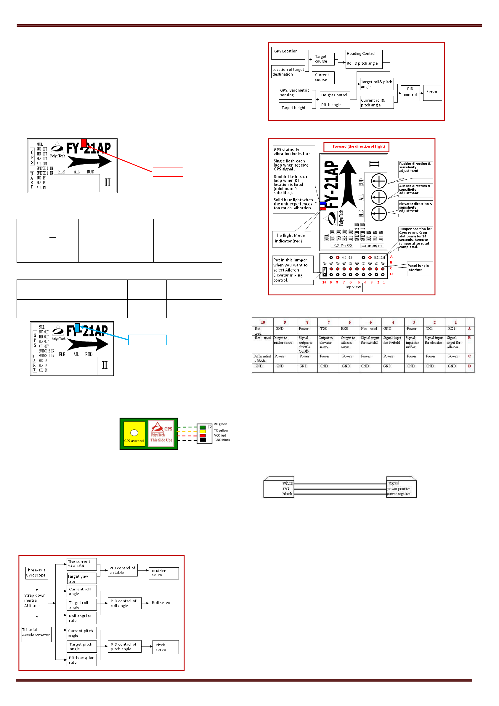
Schematic diagram of navigation control:
The Interface of FY-21AP
By observing this red LED, you can easily re-confirm your Flight Mode switch settings of your
radio:
Blue LED
The Blue LED light indicates the GPS status & vibration level experienced by the FY-21AP:
The interface and features of the GPS circuit board
TX0:Data transmission. Connect to the FY-21AP RX pin.
RX0:Data receive. Connect to FY-21AP TX pin.
Interface Features: TTL level
Baud rate: 38400
Data bits: 8
Stop bits: 1
Parity: None
GPS Data refresh rate: 10Hz
a. If GPS cannot fix the aircraft location
(minimum 5 satellites), only Mode 1 (Deactivated) and Mode 2 (Stabilized Mode) will
function. Mode 3 and Autopilot will not be functional.
b. Install the GPS Module with the antenna face up (see above). DO NOT install next to metal or
carbon fiber and other shielding material, which may block satellite signal.
c. Install the GPS Module away from electromagnetic sources such as ESC‟s, power wires,
servo wires and video transmitters.
GPS – Satellite Signal Lost During Autonomous Flight
GPS provides the aircraft geographic positioning, altitude, speed and flight direction.
With this data the FY-21AP can perform the Autopilot Modes.
In case GPS signal is lost during flight – e.g. in very cloudy weather - the autopilot will be
switched off automatically. The FY-21AP will go into Mode 3: Fixed Altitude Stabilized
Flight Mode until GPS position is regained.
After GPS signal is regained the plane will resume the Autopilot Mode.
FY-21AP Version II - Schematic diagram of balance control:
Panel for Pin Interface:
①Channel 8is optional. It will output throttle control signal only if the FY-21AP is linked to the FY-606
Data Radio
FY-21AP Electrical Connection and Diagram
Power supply
The FY-21AP operates between 4 to 6 volts input.
FY-21A is powered via the Receiver connection.
If your plane is Electric powered, the Receiver power supply is normally from the ESC built-in
Battery Elimination Circuit (BEC).
Alternately, you can supply the Receiver and FY-21AP via a separate BEC.
For Gas or Nitro powered planes, you will require a battery to power the Receiver and FY-21AP.
Connection to RC Receiver
a) Connection between the FY-21AP and Receiver output is via the supplied wire:
FY-21AP requires a minimum of 6-channel RC receiver.
b) 3 Receiver channels are used for aileron, elevator and rudder signal output. Connect these 3 receiver
output signals to the FY-21AP with the supplied wires.
c) 2 free Receiver channels are required to control the FY-21AP Flight Modes (3-position switch) and
Autopilot Mode (3-position switch).
d) Example of 6 channel receiver utilization (refer page 16 ):
Channel 1 = Aileron Signal Output
Channel 2 = Elevator Signal Output
Channel 3 = Throttle Signal Output
Channel 4 = Rudder Signal Output,
Channel 5 = Switch IN1 controlled by radio 3-position switch for FY-21AP Flight Modes.
Channel 6 = Switch IN2 controlled by radio 3-position switch for FY21AP Autopilot Modes.
SWITCH DEFAULT MODES
Switch IN1
a) If the FY-21AP does not detect any incoming signal to the Switch IN1 Channel Input, it will
automatically engage Mode2: Stabilized Mode.
b) However, we DO NOT recommend flying the unit with no signal input to the FY21AP Switch
Channel. It is possible that the auto balance will not function properly if the Switch channel is left
open.
c) If you do not have a 3 position switch available on your radio, you can set the flight Modes using a
two position switch. However you need to omit one of the flight modes.
For example, you may choose to set Mode 1 (Stabilization Deactivated) and Mode 3: (Fixed
Altitude Flight Mode) on your two-position switch, therefore omiting Mode 2 (stabilized flight).
GuiLin FeiYu Electronic Technology Co., Ltd http://www.feiyudz.cn E-mail: service@feiyu-tech.com page 2

GuiLin FeiYu Electronic Technology Co., Ltd http://www.feiyudz.cn E-mail: service@feiyu-tech.com
Switch-IN1
Signal input
900-1200μs
1200-1800μs
1800-2100μs
Functional Mode
Deactivated
Stabilized Flight Mode
Fixed Altitude Flight Mode
Switch-IN2
Signal Input
900-1200μs
1200-1800μs
1800-2100μs
Function Mode
Return to Launch
(RTL)
Autopilot
Deactivated
Auto circling mode
(ACM)
Servo 1
Servo 2
Servo 3
Aileron servo
Elevator servo
Rudder servo
Servo 1
Servo 2
Servo 3
Rudder servo
Elevator servo
Don‟t connect
Servo 1
Servo 2
Servo 3
Differential
servo 1
Differential
servo 2
Rudder servo
900-1200μs Return to Launch
1800-2100μs Auto circling mode
1200-1800μs Autopilot Deactivated
900-1200μs Deactivated
1200-1800μs Stabilized Flight
1800-2100μs Fixed Altitude
Differential servo 1 input 1
Differential servo 1 input 2
FY21AP Elevator
signal output
Add-on
mixing
device
FY21AP Rudder
signal output
Stick the FY-21AP on the shock absorbing mount
A. Split shock mount
B. Completed shock mount
Switch IN2
a) If the FY-21AP does not detect any incoming signal to Switch IN2 Channel Input, it will
automatically engage Autopilot Mode 1: Deactivated (no autopilot).
b) However, we DO NOT recommend flying the unit with no signal input to Switch IN2
Channel. It is possible that the autopilot will not function properly if the Switch channel is
left open.
c) If you do not have a 3 position switch available on your radio for Switch IN2, you can set
the Autopilot Modes using a two position switch. However, you will only have two working
modes: Autopilot Mode 1 (Deactivated) and Autopilot Mode 3 (Auto circling).
FLIGHT MODE SWITCH-IN1
a) To select the modes, set your End Points Adjustment (EPA) for the 3-Position Switch:
2. Connect your Receiver Channel 4 to FY-21AP (RUD IN) and connect the rudder servo to RUD
OUT.
Aileron-Elevator Mixing
For the following aircraft: Delta Wing with Elevator signal
mixing (e.g. Flying wing elevon):
Differential Output is carried out by using a jumper as shown here.
The jumper has to be installed before powering ON as shown
below. If you install it after powering ON, the mixing function
will not take effect.
Do not remove this jumper. Leave it installed as long as you are
using the mixing function.
Rudder-Elevator Mixing
The Jumper should NOT BE USED if you want to do Rudder-Elevator Mixing, because FY-21AP does not
support Differential-Mode stabilization for rudder-elevator mixing.
Therefore, the rudder-elevator differential control for V-tailed planes must have an add-on mixing device
for the corresponding differential channel before connection to the servos:
FLIGHT MODE SWITCH-IN2 (AUTOPILOT MODE)
FY-21AP needs one free channel from your receiver to control the Autopilot Modes.
Connect this channel to “SWITCH_IN2” of the FY-21AP stabilizer.
IMPORTANT: Activation of the Autopilot Modes (RTL and Auto Circling) has priority
over the 3 flight stabilization modes controlled by SWITCH-IN1. If you wish to use the
Flight Mode controlled by Switch IN1, you must de-activate the Autopilot Modes via
Switch IN2 first.
IMPORTANT: RADIO PROGRAMMING
1. Remove all existing mixing function already programmed in your radio.
2. The FY21AP will do all the differential mixing, not your radio.
3. Program your radio like a traditional plane layout (rudder, aileron and elevator).
VIBRATION
a) The AFSS in the FY-21AP is vibration-sensitive. To optimize its stabilization capability, vibrations
reaching the unit must be kept at a minimum.
b) Therefore when installing this flight stabilizer, we highly recommend that you install it with the
supplied shock absorbing platform.
c) The algorithm in the FY-21AP compensates from normal levels of flight vibrations. However, if the
vibration experienced by the unit exceeds the acceptable level, it may not work normally or may even
stop working altogether.
d) To keep vibration at a minimum, install the FY-21AP away from the engine or any other vibration
sources.
e) The included vibration-absorbing mount will meet the damping requirements of electric powered
aircrafts and most gas / nitro planes.
f) If you receive your shock absorbing mount uninstalled (A), please complete it as shown below (B):
Plane Connection Layout:
Normal / Traditional servo layout:
Plane without aileron servo:
Delta-winged plane servo:
For all fix wing aircrafts (including the traditional rudder, aileron and elevator planes, and planes
with aileron and elevator mixing, and so on, if the rudder is NOT used in any mixing function, you
can have two options ,as shown below:
1. Keep the FY21AP rudder channel (RUD IN, RUD OUT) open (not used). Connect the
Rudder servo directly to your RC Receiver. Autopilot can still work normally; eg.auto
circling and RTH.
GuiLin FeiYu Electronic Technology Co., Ltd http://www.feiyudz.cn E-mail: service@feiyu-tech.com page 3
g) Use the supplied Velcro strips to mount the FY-21AP to the suspended platform (below).
h) Mount the entire unit to the plane using double sided tape (recommended), Velcro, screws or glue.
Only the vibration damping pad is enough when the vibration is not so big.
The supplied Damper Mount will take care of most aircraft vibrations, unless it is (the vibration) too
severe.
WARNING: VIBRATION CHECK
Even with the shock absorbing mount, your aircraft installation may not meet the damping requirements of
the AFSS. To confirm correct vibration damping:
A. Connect all wires between the Receiver, FY-21AP and Servos, install the unit as recommended
(ensure correct orientation).
B. Run the plane engine or motor at different throttle levels. DO NOT TAKE OFF.
C. Move the throttle level at different positions & maintain for 20 seconds at each level.
D. At each throttle position, observe the state of the blue light.
E. If the blue lights stay ON solid then the vibration dampening is not enough.
F. If the blue light does not stay ON solid, this indicates the vibration dampening requirements have
been met.
G. Please note that the blue light is also an indicator of GPS connection. However, the blue LED takes
priority to indicate vibration status first, then the GPS connection.
FY-21AP INSTALATION: ORIENTATION, POSITION & LEVEL
i. The FY-21AP has an arrow printed on the top of it. Orientate the arrow towards the front of the craft
(i.e. direction of flight).
ii. When installing, please keep the FY-21AP horizontal and as close as possible to the "Centre of
gravity" (CG) of the aircraft.
iii. The control benchmark of FY-21AP is its horizontal position. Therefore, ensure the FY-21AP is in
the horizontal position when the plane is in level flight.
iv. If there is deviation between the FY-21AP horizontal position and the plane‟s level flight, it may
cause the neutral value to be different between Mode 1 (Deactivated) and the stabilized Flight
Modes. This difference may result in the following:

GuiLin FeiYu Electronic Technology Co., Ltd http://www.feiyudz.cn E-mail: service@feiyu-tech.com
The knobs control both
gain and servo direction.
The gyro gain is lowest
when the knob in the
middle. i.e. The further
away from center, the
higher the gyro gain.
Turning the knob left or
right off-center will change
servo direction.
Rotate right
Rudder moves to the left
Rotate left
Rudder moves to the right
FY-21AP IN STABILIZED MODE
v. We do not recommend using your transmitter trims to level your aircraft in Auto Balance
mode, as the new trim settings will affect your aircraft when you revert to Manual Mode. It is
best to land and adjust the FY-21AP installation.
FY-21AP Pre-Flight Checking and Debugging
PRE-FLIGHT CHECK:
The following procedure explains how to check for correct servo control direction upon FY21AP activation. You should also check that the FY-21AP does not control the aircraft servos when
in Mode 1: Deactivated Mode.
STEP 1: DIAL ADJUSTMENT
Adjust the three dials on the FY-21AP so that the arrow is in the middle, as shown below. Then
rotate all dials in one direction (does not matter which direction):
STEP 2: STABILIZED MODE
Place the plane on a horizontal surface with both the wings and pitch leveled. Centre the rudder
surface. Move your radio 3-position switch so that the FY-21A is in Mode2: Stabilized Mode.
STEP 3: AILERON CHECK:
Incline the plane to the right (roll right). The ailerons should give a control signal to counter
this roll direction (see below). Same as when rolled to the left. If the ailerons move correctly,
the knob has been turned in the right direction. You can now adjust gain by moving nearer (low
gain) or further away (high gain) from center:
Move the Rudder knob to the opposite side (from Centre) if the servo movement is incorrect:
Adjust Rudder gain according to your aircraft requirement (lowest gain nearest to centre, highest gain
further away from centre).
STEP 6: FLIGHT TEST AND SENSITIVITY ADJUSTMENT
Steps 1 to 5 should enable you to correctly set your servo movement direction via the 3 knob dials.
To fine tune your aircraft attitude control via the FY-21AP, some flight testing has to be performed.
For the first flight it is recommended that the gains not be set too high. This will reduce large
oscillation or „flight overcorrection‟.
After the flight take off, switch the device from Mode 1 (deactivated) to Mode 2 (Stabilized mode).
If you see oscillation of the wings, this indicates the Aileron gain is set too high. Switch back to Mode
1 (deactivated) and land the airplane.
Reduce the sensitivity (move dial towards centre position) and fly again. You should see improvement
in wing attitude. Adjust until you are satisfied with the level of wing stabilization.
Too much Elevator gain will show the tail moving up and down (rocking). Too much Rudder gain will
show tail wagging. Reduce gain until this flight overcorrection is gone.
Alternately, if you find the flight correction is not enough, you can increase gain accordingly.
WARNING: SAFETY PRECAUTION – MUST READ
I. The purpose of the FY-21AP (AFSS) is to stabilize the aircraft. It is not an Anti-Stall device. The
stabilization action of the FY-21AP will fail if the aircraft is stalled. Please ensure adequate throttle
especially when in the Autopilot Modes.
II. The aircraft direction is controlled by you, at all times. Make sure you know where you are going.
III. The FY-21AP is for your enjoyment. But do not fly the plane into a crowded area, where your aircraft
can cause serious injury if it crash. Please be responsible when using this product.
IV. Besides the regular pre-flight checks (we recommend a checklist). Always check the correct operation
of the stabilizer on the ground prior to take off.
V. Any electronic and hardware on an RC aircraft can fail over time. Please assess your aircraft and
electronic condition before use. FeiYu Tech is not responsible for any losses or injury as a
consequence of using this product.
VI. Please ask an experienced RC Plane pilot for assistance if you are a beginner. It is absolutely critical
that you get flight basics before proceeding. You also need directions to correctly assemble, take off
and control your RC Model. We highly recommend joining your local RC Model club.
VII. Never fly close to people, buildings, overhead wires, vehicles, trees or closed spaces. You could
VIII. Minimum flying distance should be 20 foot from you and others. Learn about emergency procedures
XII. Never use the remote control within three miles of your local airport. You could endanger full scale
XIII. Keep all electrical equipment away from rain water, moisture and extreme high temperature.
XIV. DO NOT OPEN any FY-TECH Attitude Flight Stabilization System (AFSS) unit or any of our other
seriously injure yourself or someone else.
should you lose control of your aircraft.
IX. Keep the RC Model and related equipment away from children. RC planes are not toys. Children
must be supervised at all times if they are allowed to fly.
X. Please operate your RC plane within the permitted area of your local government. For more detail,
please check with your local council or government.
XI. If you are not using 2.4 GHz spread spectrum radio, never turn on your radio before checking and re-
checking that you're the only one using the frequency. You could cause a crash of another aircraft if
the frequency is the same. For security; please obey to the local frequency regulation.
aircraft instruments. Lives could be lost.
modules. Opening or dismantling the module cover will null any kind of warranty we and our
distributor have on the product you purchased.
If the ailerons do not follow the movements shown above, simply turn the aileron knob to the
opposite side (beyond centre). You should now see the correct aileron movement.
STEP 4: ELEVATOR CHECK
Incline the plane NOSE UP. You should see the elevator move down. And when you move the
NOSE DOWN, the elevator should move up. Move the Elevator knob to the opposite side
(from Centre) if the servo movement is incorrect:
Adjust Elevator gain according to your aircraft requirement (lowest gain nearest to centre,
highest gain further away from centre).
STEP 5: RUDDER CHECK
Rotate the plane at its centre axis from left to right. You should see the following action:
GuiLin FeiYu Electronic Technology Co., Ltd http://www.feiyudz.cn E-mail: service@feiyu-tech.com page 4

GuiLin FeiYu Electronic Technology Co., Ltd http://www.feiyudz.cn E-mail: service@feiyu-tech.com
Incline FY-21AP to the right, left aileron goes up:
Incline FY-21AP to the left, right aileron goes up:
FY-21AP INSTALLATION GUIDE
Equipments list:
FY-21AP;
FYOSD;
FY-CS100A;
FUTABA remote controller;
FUTABA10 receiver;
video transmitter;
A pair of scissors,
A knife;
Double sided tape;
Battery;
Aircraft;
Some related wirings.
1. Prepare the plane, install the electrical motor, servo,
etc.
2. Aircraft installation tools may include (but not
limited to) screwdriver, scissors, knife, foam
double-sided tape, Velcro with double sided tape,
etc
3. You should be able to do some basic wire soldering
to install the FY-CS100A (main battery current
sensor).
Connection wires include FYOSD plug, connecting
wires for camera and video transmitter to FYOSD,
the data wires between FYOSD to the FY-21AP and
the connecting wires from FYOSD to the RC
receiver.
4. FYOSD connection to camera and Video
Transmitter.
5. We recommend making a hatch door for FY-21AP
installation:
i. Check the automatic movement direction of each servo.
ii. Reverse dial knob rotation if servo movement is incorrect.
14. Connect the data wirings from GPS Module and FYOSD to the FY-21AP. Velcro tape the RC
receiver to the FY-21AP. Velcro tape the FY-21AP to the vibration absorbing mount.
15. Use double sided tape to fix the vibration absorbing mount to the plane‟s center of gravity.
16. Install Current sensor between the ESC and battery:
17. Fix the camera and GPS module:
18. Arrange the wires neatly inside the aircraft cabin (avoid the GPS Module). Installation is complete.
Go fly!
6. Connect the extension wire of the video transmitter. Install video transmitter to fuselage.
7. Connecting wires for FYOSD.
8. Use the Velcro tape to install FYOSD to the aircraft cabin.
9. Connect the RC receiver to the FY-21AP.
Note: FeiYu Tech reserves the right to change this manual at any time.
——END——
Note: We reserve the right to change this manual at any time! And the
newest edition will be shown on our website www.feiyudz.cn.
10. Connect the servos to the FY-21AP.
11. Power ON and check the connecting wires. Move the control sticks and check for correct
rudder, aileron and elevator movement.
12. Set CH5 and CH6 to a 3-position switch to control the three Flight Modes and Autopilot
Modes of the FY-21AP. Set CH7 to VrC, to control the data overlay of the FYOSD.
13. Adjust the three dial knobs. Turn all in one direction.ON your transmitter and connect power
to your plane. Switch the FY-21AP to Flight Mode 2: Stabilized Mode:
GuiLin FeiYu Electronic Technology Co., Ltd http://www.feiyudz.cn E-mail: service@feiyu-tech.com page 5
 Loading...