

8 7 6 5 4 3 2
1
No.
ESC4
out
ESC3
out
ESC2
out
ESC1
out
GND
Power
TX
RX
A
Power
Power
Power
Power
CH5
(Switch)
CH 4
(Rudder)
CH 3
(Throttle)
CH 2
(Elevator)
B
GND
GND
GND
GND
GND
Power
CH 1
(Aileron)
NULL
C
Switch number
1 2 3
4
ON
For Factory
use only
Flight Mode
Selection
Flight Mode
Selection
Not
used
OFF
Always OFF
position
Flight Mode
Selection
Flight Mode
Selection
Not
used
Blue LED
Continuous flashing
On Solid
Flight Modes
MODE 1
MODE 2
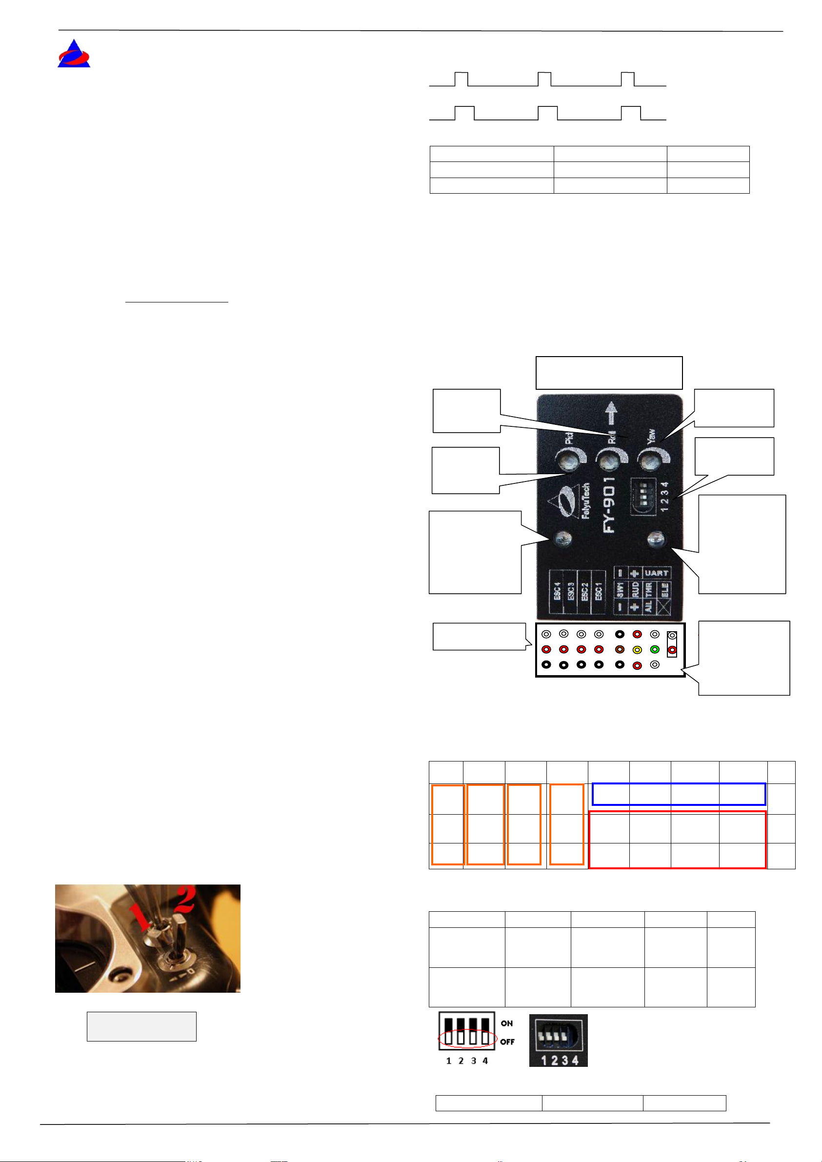
Receiver signal output
900-1800uS
1800-2100uS
FY-901 Function
Auto Stabilization mode
3D Mode
POINT ARROW FORWARD
(TOWARDS FLIGHT
Roll
sensitivity
knob
Pitch
sensitivity
knob
Blue LED: Flight
mode indicator.
Always On: 3D
mode.
Singleflashing:Aut
o Stabilization.
Interface pin panel
B
A
8
C
7
6
5 4 3 2 1
Yaw sensitivity
knob
Function DIP
switch
Red LED: Solid
ON indicates
vibration is too
severe.
Flashes when
stationary: indicate
need for gyro
initialization.
Jumper installed
during gyro
initialization.
Do not insert
jumper during
normal use.
900-1800us Auto Stabilization
Mode
1800-2100us 3D Mode
FeiyuTech
Switch setting example
Dear Pilot,
GuiLin FeiYu Electronic Technology Co., Ltd http://www.feiyudz.cn E-mail: service@feiyu-tech.com
FY-901 Flight Stabilization System
installation & operation manual
Thank you for choosing FY-901 as your inertial stabilization solution. This
manual mainly introduces FY-901 firmware for Multi-rotor flight system.Please read
this manual carefully before using the system to ensure proper use and operation.
Note:
To set up and use of FY-901 in multi-rotor flight require a certain degree of
multi-rotor flight and RC experience.
If you have never flown a multi rotor aircraft before, we recommend that you
don’t install this equipment on your own. Please seek assistance from an experienced
RC multi-rotor pilot.
If you are already an experienced multi-rotor pilot, you will find the installation
simple. Please follow the instructions as stated in this manual and you won’t go
wrong.
Remember, SAFETY ALWAYS FIRST.
If you need any technical support, please feel free to contact us:
service@feiyu-tech.com.
INTRODUCTION
FY -901 has integrated three-axis gyro and three-axis accelerometer, which
controls the aircraft movement in three-dimensional space. FY-901 can be used in
multi-rotor copter.
b) If you do not connect the Switch channel with your RC Receiver or FY-901 does
not detect any incoming signal through this input channel, it will automatically
engage Mode 1- Auto Stabilization Mode. However, we do not suggest flying the unit
with no signal input to the Switch Channel.
c) Please note that even though there are Throttle Input and Throttle Output from
the FY-901, the system does not control the Throttle to hold the altitude, you must
always control the Throttle to keep flying altitude.
FY-901 interface for multi-rotor
Aircraft Apply
The FY-901 for multi-rotor copter can be used in the following models:
Quadcopter X-Type
Quadcopter cross-Type
Y3-copter
Any other configuration apply need, please e-mail us: service@feiyu-tech.com.
RC Radio suitability:
The FY-901 has been tested to work well with the following RC system:
Robbe-Futaba PPM / PCM 1024 / PCM G3 mode, 2.4G systems
Graupner / JR PPM 8, PPM 12, SPCM mode;
MPX PPM8, PPM 12 with UNI mode
any other system with a neutral position of 1.5 ms (standard in most RC Radios).
The FY-901 Operating Mode for multi-rotor copter supports two flight modes :
Mode 1: Auto-Stabilization mode. In this mode, the FY-901 will automatically
command the control surface of the aircraft to maintain level flight all the time(sticks
in the middle position). The sticks correspond the roll and pitch attitude angle.The
netual position of sticks is 0 degree and the maximum angle is 55 degrees.
Mode 2: 3D Control Mode. In this mode, the balancer utilizes its 3-axis
gyroscope to sense roll velocity and flight attitude. If no input is given by the pilot
(sticks in the middle position) the FY-901 will lock the current aircraft attitude. This
prevents from rolling of the aircraft at the axial plane and maintains its current
posture. Therefore, the aircraft can be easily maneuvered to complete a variety of 3D
movements with added stability and smoothness.
Pin interface to sort the list
Switch Setting for FY-901 Flight Modes
To activate the different flight modes, use a free Receiver channel (e.g. Channel 5) to
output the appropriate signal to FY-901.
a) Use a 2 way-switch from your RC radio as in the example below:
RC Receiver Signal output
DIP Switch Function:
Blue LED
GuiLin FeiYu Electronic Technology Co., Ltd http://www.feiyudz.cn page 1
GuiLin FeiYu Electronic Technology Co., Ltd http://www.feiyudz.cn E-mail: service@feiyu-tech.com
Flight Mode Status
Auto Stabilization
3D Mode
Red LED
OFF
Aircraft is
stationary but
Red LED Flashes
ON Solid
Status
Indicator
Normal
Need to initialize
the gyro/ moving
High Vibration Detected.
Does not meet system
requirement.
Wire color
Receiver channel
White (red and black)
Aileron
Channel 1
Orange
Elevator
Channel 2
Green
Throttle
Channel 3
Yellow
Rudder
Channel 4
Brown
Controlled 2-Way switch
Channel 5
1 2 3
4
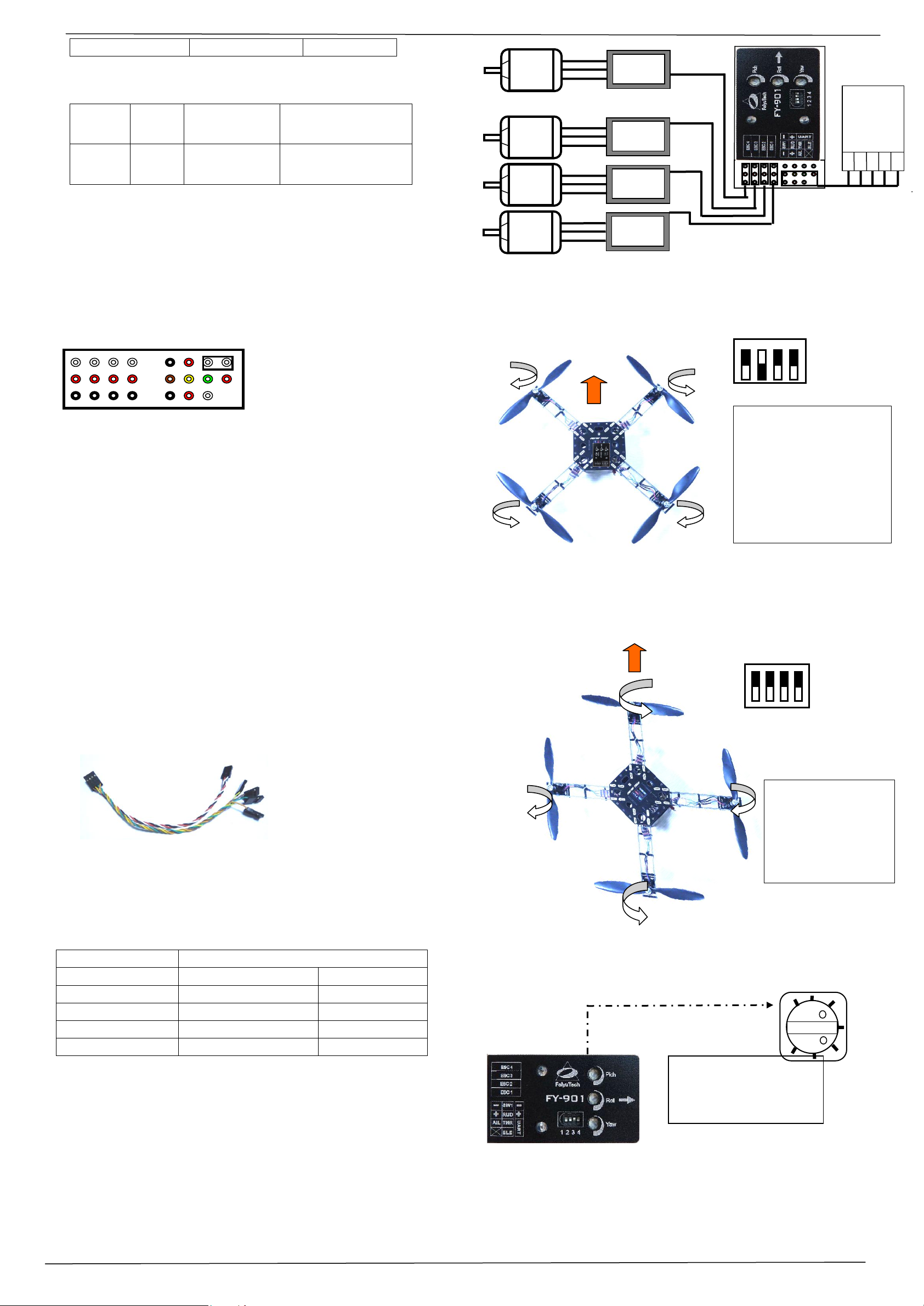
十 - Type Quad Layout:
1 = ESC 1 CCW
2 = ESC 2 CW
3 = ESC 3 CCW
4 = ESC 4 CW
cw = clock wise
ccw = counter clockwise
ESC4
Motor4
ESC3
Motor3
ESC2
Motor2
ESC1
Motor1
RC
Receiver
B
A
8
C
7
6 5 4 3 2 1
2 4 3
1
ON
OFF
1 2 3
4
X-Type QuadCopter Layout:
1 = ESC 1 CCW
2 = ESC 2 CW
3 = ESC 3 CCW
4 = ESC 4 CW
cw = clock wise
ccw = counter clockwise
1
2 3 4
OFF
ON
Turning the knob to the
left will reduce the gyro
gain ,turning to the right
increase the gyro gain.
0 Min
100 Max
0 Min
Red LED
Gyroscope initialization (re-setting):
Out of the box, the FY-901 has been fully initialized. However, if the following
condition occurs, resetting the gyro is recommended:
1. The device is kept unused for a long time.
2. There is a change in environmental temperature of over 30 degrees.
3. The red LED light flashes even when the aircraft is stationary.
Initialization / Reset Procedure
Install the jumper as shown in this picture:
Power-ON the FY-901 and keep it stationary for at least 20 seconds. You will
notice the red light blinks at two different rates (or turns off). Re-setting of Gyro
is completed. Disconnect power, unplug the jumper and keep it in a safe place
for future use).
NOTE:
Carry out this re-setting procedure only if the condition (above) occurs. It is
not recommended to regularly reset the gyro. It is not necessary.
The stabilizer unit does not need to be in a horizontal position during
initialization. However, you must ensure there is no vibration during this process.
If you suspect shaking has occurred, just restart the resetting process.
FY-901 power supply
X-Type Layout
Cross Type Layout
FY-901 working voltage = 5 to 6V.
The FY-901 requires stable power input. Therefore, we highly recommend using
an external BEC power supply with minimum 3A output. The higher the better.
Be sure to remove the Red wire from your ESC plug if using an external BEC.
BEC should be plugged into your RC Receiver. Power is sent to the FY-901 via
Channel 1 input.
FY -901 colour coded cable to RC Receiver:
RC Receiver Requirement
a) FY-901 requires at least a 5-channel receiver
b) Plug in the cable into the FY-901 and connect to the RC Receiver following
these colour codes:
c) Note Channel 5 will output the signal to control the 2 flight modes of the
FY -901. Therefore assign 2-way switch to this channel.
QUADCOPTER SET UP
The knob for Quadcopter
Y3-COPTER SET UP
GuiLin FeiYu Electronic Technology Co., Ltd http://www.feiyudz.cn page 2

GuiLin FeiYu Electronic Technology Co., Ltd http://www.feiyudz.cn E-mail: service@feiyu-tech.com
1
2
3
4
OFF
ON
Motor 1
Motor 2
Motor 3
Servo for
RUD,control the
Motor 1
deflexion
Y3-Copter Layout:
1 = ESC 1 CW
2 = ESC 2 CW
3 = ESC 3 CCW
cw = clock wise
ccw = counter clockwise
Servo for RUD,control the Motor 1 deflexion,aircraft turn left, servo
must control Motor1 Tilt leftaircraft turn right ,servo must control
Motor1 Tilt right. If not ,adjust the RUD knob to change the direction.
The Pitch and Roll for the pitch and roll sensitivity,turning the knob to the
left will reduce the gyro gain ,turning to the right increase the gyro gain.
The Yaw for the yaw servo sensitivity, the gyro gain is lowest when the
knob in the middle. i.e. The further away from center, the higher the gyro
gain.
Turning the knob left or right off-center will change servo direction for
stabilization.
0 Min
100 Max
0 Min
RC
Receiver
ESC4
(Servo)
ESC3
Motor3
ESC2
Motor2
ESC1
Motor1
Elevator and Rudder trims to counter any drift.
VIBRATION DAMPING
a) The FY-901 flight controller algorithms can filter and operate under normal
vibration levels, however if the vibration and shock experienced by the onboard
sensors is too big, stabilization can fail and the system can shut down altogether.
b) Because of this, to achieve the best stabilization and flight performance out of
the FY-901, you must minimize the amount of vibration on the aircraft as best you
can.
c) Examples of vibration reduction steps that can be taken:
i) Ensure your motors are mounted properly and squarely.
ii) Balance your propellers regardless of the manufacturer’s claim of perfect
balance out of the factory.
iii) Balance your motor bell housing (if possible).
iv) Ensure rigidity of your frame (will not flex with
motor rotation).
v) Use appropriate propeller length and pitch for the
weight of your aircraft.
d) The FY-901 is supplied with the shock absorbing
mount and double-sided foam padding dampers. Please use them as the right picture:
CHECKING FOR VIBRATION
a) Install the FY-901 as per the recommendations of this manual, including
directions of propeller rotation.
b) Throttle up in Mode 1 (Auto Stabilized Mode) but do not take off!
c) Observe the red LED on the FY-901 module.
d) If the red LED light remains OFF, this indicates your aircraft vibration level is
acceptable.
Instead, If the red LED light still goes ON and remains lighted, your aircraft does
not meet the vibration level requirement. Please take action to reduce the onboard
vibration level.
FY-901 Preflight Inspection and Initial Testing
The knob for Y3-copter
FY-901 Module Installation
1. FY-901 has an arrow indicator on top. Please ensure this arrow is pointed
towards the direction of flight.
2. Installed the module horizontally, and as close as possible to the aircraft center.
A more centered installation will result in more stable drift free of hover.
3. The FY-901 sets its own benchmark of what is ‘horizontal’. Install the module
based on the hover characteristics of the aircraft in Mode 1 (Stabilized Mode).
Shimming the module may be required to get the aircraft to hover perfectly.
4. You may also fine tune the stability of your aircraft using your radio Aileron,
GuiLin FeiYu Electronic Technology Co., Ltd http://www.feiyudz.cn page 3
Pre-flight testing for aircraft control:
1. Adjust all stick trims to the middle, Remove all propellers.
2. Activate throttle to start up the motors. Check the rotation direction of each
motor and make sure it is turning in the right direction.
3. Re-Install propellers.
4. Check again that the rotation is correct.
5. Check the FY-901 sensitivity control knobs. Please ensure the dials are beyond
12 o’clock. Anything less than that may result in no flight stability for this first flight.
Tie down test: Before proceeding, we highly advise that you tie down the aircraft to
the ground to prevent from any possibility of going out of control during this initial
flight tests.
6. First test lift off: Advance your throttle stick, but do not take off (usually
around 30% throttle). Let the aircraft float just enough so that you can see the
aircraft reaction as you move your Aileron, Elevator and Rudder sticks.
7. If the control movement is reversed, just reverse the channel on your RC
transmitter.
8. After step 7, you can take off higher. If the aircraft hovers well, you can
proceed to remove the aircraft from the tie down test.
9. Observe the flight for stability and oscillations as the aircraft hovers higher.
10. If you feel there is not enough stability (e.g. excessive drifting), you can
increase the sensitivity of the three dials.
11. If there are rapid oscillations, reduce the corresponding sensitivity knob.
12. More fine tuning adjustment can be done via the FeiYu software (you will need
the TTL-USB cable for this).
Pre-flight Debugging
1. If your aircraft fails to lift off and hover for the initial pre-fight tests, please
check the following:
a) Check whether the connection of ESCs is all correctly plugged in. Take time
to check and re-check that each ESC has been plugged in and that the plugs are
correctly placed.
b) Please ensure there is no short circuit of the power (positive) and GND wires.
Short circuits can damage the internal processor chip which is beyond repair
(voiding all warranty).
c) Check that all motors are rotating in the direction noted in this manual.
Ensure you have selected low timing for your ESC (if you are not using FY ESCs)
d) Ensure you have selected low timing for your ESC (if you are not using FY
ESCs).
——END——
Note: We reserve the right to change this manual at any time! And the newest
edition will be shown on our website www.feiyudz.cn.
 Loading...