

Page 1

Guilin Feiyu Electronic Technology Co., Ltd
Feiyu Tech
FY-31AP Flight Stabilization System
Installation & Operation manual
Dear Customer:
Thank you for choosing FY-31AP as your autopilot system. Please read
this manual carefully before using the system to ensure proper use and
operation.
The installation and use of this device require some skill and knowledge
in flying remote controlled fixed wing aircraft.
If you are a complete beginner and have never flown one before, we
do not recommend you install this device on your own.
Please find assistance from an experience RC Pilot who may provide
you with the basic knowledge required to use this device
successfully.
If you are already an experienced flyer, you will find the FY31AP
installation to be easy and logical. Just follow this manual and you
won’t go wrong.
If you need any technical support you can send mail directly to:
service@feiyu-tech.com
1. Attitude Flight Stabilization System (AFSS)
FY31AP is an inertial attitude measurement instrument used for
automated stabilization of fixed wing model aircrafts and simple three
axis camera gimbals.
FY31AP has an integrated three-axis gyro and three-axis accelerometer
which controls the aircraft movement in three - dimensional space.
2. Barometric Sensing and GPS
FY-31AP control module incorporates an accurate barometric pressure
sensor. At start up, the take-off air pressure is measured, providing the
autopilot with an accurate relative height data.
While the GPS module enables the autopilot to calculate the flight
course and exact location of the aircraft. If the FY31AP is not connected
GPS module, the autonomous flight system cannot be engaged and it
will function purely as a flight stabilizer.
After connecting the GPS and booting up, the FY-31AP will search for
GPS positioning signals, the first time the GPS positioning successfully
and the satellites quantity at least 4, then the FY-31AP will remember
this position as the home point
3. Function Of FY-31AP
By using your remote control, the FY-31AP can be turned on or off for
the following functions:
Level flight – When stabilization is activated, the FY31AP will
automatically control the aircraft for smooth easy flying. For
beginners in RC aircraft flying, this is advantages as it makes flight
easier and increases the student pilot self-confidence. The system
can be activated throughout the entire flight duration, from take off
to landing.
Emergency Recovery - If you lose orientation release all control
sticks, maintain throttle and switch ON the FY31AP. The unit will
automatically send the correct signals to balance of the aircraft and
regain level flight, giving you time to get your orientation and fly the
plane back to safety.
Autonomous flight –with the GPS module the autonomous flight
system of the FY31AP will enable you to fly fully autonomous, with
up to 8 waypoints(above firmware V2.1, waypoints add to 20. )
settings on the FY Ground Control Station software.
Ground Control Station – the FY GCS software will enable you to fly
autonomously to up to 8 waypoints(above firmware V2.1, waypoints
add to 20. ), display in-flight telemetry data, and record that flight
for replay and analysis (this requires the optional Data Radio
hardware).
Automated circling - by activating this function, the aircraft will
automatically circle the selected area at a fixed altitude(FY-31AP has
50m altitude protection limited,if the switch point altitude below
50m,FY-31AP will automatic climb to 50m.) the centre of the circle is
the current point. You can set the circling radius, the default radius is
80 meters.
Return to Home – You can set autonomous return to home via a 3
way switch or through your failsafe setting, enabling you plane
returning to home should it lose your transmitter signal. Upon
reaching the home point it will automatically engage auto circling,
while it waits for your further instructions. (FY-31AP has 50m
altitude protection limited,if the switch point altitude below
50m,FY-31AP will automatic climb to 50m.)
First Person View - for long-distance RC flight via video transmitter,
the FY31AP will maintain the balance of your aircraft. You only need
to control the heading of your aircraft and enjoy the view.
Firmware upgrade – The FY31AP firmware is upgradable by
connecting to your computer via a USB TTL cable. As Feiyu Tech
continuously improves the FY31AP system, firmware upgrades will
be released periodically.
4. Optional Upgrade with FY-OSD and Data Radio
The FY-31AP provides an optional upgrade combining with the FY-OSD
and the Data Radio. With this add-on, you will receive:
First Person View (FPV): by connecting this interface to the FY-OSD,
telemetric data such as GPS, flight navigation, AHI can be displayed
on your downlink video. On the other hand, it will be easier to
operate FPV with the functions of automatic balance and automated
return to home.
Real time telemetry – real time by-directional telemetry is
monitored directly by your ground station computer. Changes to
aircraft altitude and flight path can be controlled from your ground
station computer.
Record and monitor your flight - you can monitor and download
your flight path into your ground station computer.
For more information, please refer to the FY-OSD and FY Data Radio
manual.
5. FY-31AP Package Content
• FY-31AP control module *1;
• GPS receiver * 1;
• RC receiver connecting wires * 1;
• Velcro double sided tape * 2;
• Some related wire.
• Instruction manual * 1;
6. Technical Specification and working requirement
FY-31AP module:
Input voltage : 4.0 ~ 6.0 Volt;
Current draw : 50mA (5V);
Size : 47 x 27 x 20 mm;
Weight (excluding wires) : 25g;
Temperature range : -25 ° C ~ +70 ° C;
Maximum rate of rotation : ≤ 2000 ° /s
GPS module:
Input voltage : 3.0 ~ 3.3 Volt;
Current draw : 60mA (3.3V);
Size : 32 x32x 10 mm;
Weight (excluding wires) : 22g;
Temperature range : -25 ° C ~ +70 ° C;
7. Application
The FY-31AP can be installed in the following aircraft :
1) Normal / Traditional fixed-wing planes;
2) Delta-winged plane with rudder;
3) Delta-winged plane without rudder;
4) Plane without aileron;
5) V-tail plane with aileron;
6) V-tail plane without aileron;
7) Any other configuration , please e-mail us for enquiry:
service@feiyu-tech.com
8. Remote control system requirement
The FY-31AP has been tested to work with the following RC systems:
Robbe-Futaba PPM / PCM 1024 / PCM G3 mode, 2.4 GHz systems;
Graupner/JR PPM 8, PPM 12, SPCM mode;
MPX PPM8, PPM 12 with UNI mode
Any remote control system using the standard of 1.5 ms neutral
position.
9. FY-31AP Flight Modes
The FY-31AP has three flight modes, you can activate any of the flight
modes via a free Receiver channel and a 3-position switch (named as
“SW1”) on your computer radio.
Mode 1: Deactivated Mode. In this mode, all control of the aircraft
is by the pilot. The FY-31AP does not participate in flight control.
Mode 2: Stabilized mode
.
In this mode and your transmitter control
sticks at center, the FY31AP will continuously send out controlling
signal (aileron, elevator, rudder) to ensure the aircraft maintains a
stabilized, horizontal flight and constant flight direction. In this
mode FY-31AP will not allow acrobatic flights.
Mode 3: Navigation mode. In this channel you can select one of
the following mode to be activated.
A: Path Navigation mode, In this mode, the waypoint will be set
according to the flight path to automatic flight.
B: Fixed altitude flight ,When this function is activated, the unit will
maintain your aircraft altitude. You only need to input the right
throttle level and point the plane in the direction you want to go.
C:Heading lock flight: once this mode is activated, the autopilot
will auto calculate out a rays as the path, the ray‘s starting point is
the current point, and the angle is the current heading angle.
10. FY-31AP Autonomous Flight Modes
Three autopilot modes are incorporated into the FY-31AP, you can set it
via a free receiver channel and a 3-position switch (named as “SW2”).
Guilin Feiyu Electronic Technology Co., Ltd http://www.feiyudz.cn E-mail: service@feiyu-tech.com Page 1
Page 2
Guilin Feiyu Electronic Technology Co., Ltd
Flight
mode
Stabilized
Mode
Deactivated
Mode
Navigation
Mode
Return To
Launch
(RTL)
Auto Circling
(ACM)
Blue LED
light
indicator
Stay on
solid
continuous
flash
Single flash
Double
flash each
loop
Continuous
flashing 3
times each
loop
Status
Too much
vibration
No GPS or
GPS still
not lock
Need to
initialize
Gyro or are
moving
GPS location
fixed
(4 satellites)
Red LED
light
indicator
Stay on
solid
Stay off solid
Continuous
flashing
Continuous
double flash
each loop
Green--Signal
Red--- +3.3V
FY-31AP
Autopilot mode 1:
Deactivated. The autopilot function is not
activated , the flight modes are determined by the “SW1”.
Autopilot mode 2: Auto Return To Launch(RTL). When activated
in this mode, the FY-31AP will automatically fly the plane back to the
take-off point, while maintaining altitude. (FY-31AP has 50m altitude
protection limited,if the switch point altitude below 50m,FY-31AP
will automatic climb to 50m.)Upon reaching the launch area, the unit
will automatically fly the plane in a circle at a default circling radius
of 80 meters.
Autopilot mode 3: Auto Circling Mode (ACM). When activated this
mode, the plane will immediately fly in a circle.
circle is the point of activation
. The default circle radius is 80 meters.
The centre of the
The aircraft altitude will be automatically maintained throughout the
ACM. (FY-31AP has 50m altitude protection limited,if the switch
point altitude below 50m,FY-31AP will automatic climb to 50m.)
Autopilot stall warning
a. The FY-31AP has some control over the throttle channel. Therefore,
when flying in Autopilot Modes, please ensure you have enough
forward movement to prevent stalling.
b. FY-31AP may have a control over the throttle channel, but the
throttle control signal is base on the stick control signal and will
auto adjust according the altitude and speed then output the
combined signal. If your forward movement cannot compensate for
the autopilot’s active altitude hold, your aircraft will stall.
c. This is especially important if RTL is part of your RC failsafe. In the
event of RC Link lost, you can set RTL into your Receiver failsafe.
However, please DO NOT forget to also set your throttle failsafe to
between 25 % to 50% to ensure the plane does not stall.
d. Never set your throttle failsafe to zero. If you do so, your aircraft will
RTL in a continuous stalled flight which will result in a crash.
Attention: FY-31AP can work in automatic flight mode, though without
OSD module. Whether you have been connected the OSD or not,
FY-31AP can work normally. But if the FY-31AP is not connected GPS
module, it will function as purely as a flight stabilizer. The autonomous
flight modes cannot be engaged.
11. Red LED Flashing & Gyroscope Re-set:
If the following conditions occur, the FY-31AP initialization is
recommended:
(1) The device has not been used for a long time.
(2) There is a change in environmental temperature of over 30 degrees
since last flight.
(3) The Red LED flashes continuously even when the FY-31AP remains
stationary about 20s, and you never activate the motor.
(4) If the Red LED is on solid all the time even when the FY-31AP is
stationary, it means the gyroscope is faulty, and the unit need to be
sent back for repair.
12. Gyroscope Re-set procedures:
(1) Carry out this re-setting procedure only if the above occur. We do
not recommend regular re-setting. It is not necessary and not
recommended.
(2) The stabilizer unit does not need to be in a horizontal position
during initialization. However, you must ensure there is no vibration
during this process. If you suspect shaking occurred, just restart the
initialization / resetting process.
Initialization / Reset Process
(1) Install the jumper as shown in this
picture:
(2) Power-ON the FY-31AP and keep it
stationary for at least 20 seconds.
You will notice the red light blink
with two different rates.
(3) After 20 seconds, the re-setting / initialization is complete.
(4) Disconnect the power, unplug the jumper & remove it (keep safe for
future use).
Note: Navigation Mode: means one of the three modes. Path Navigation mode,
Fixed altitude flight mode and Heading lock flight mode. You can select via the
GCS Software. The default mode is Path navigation mode.
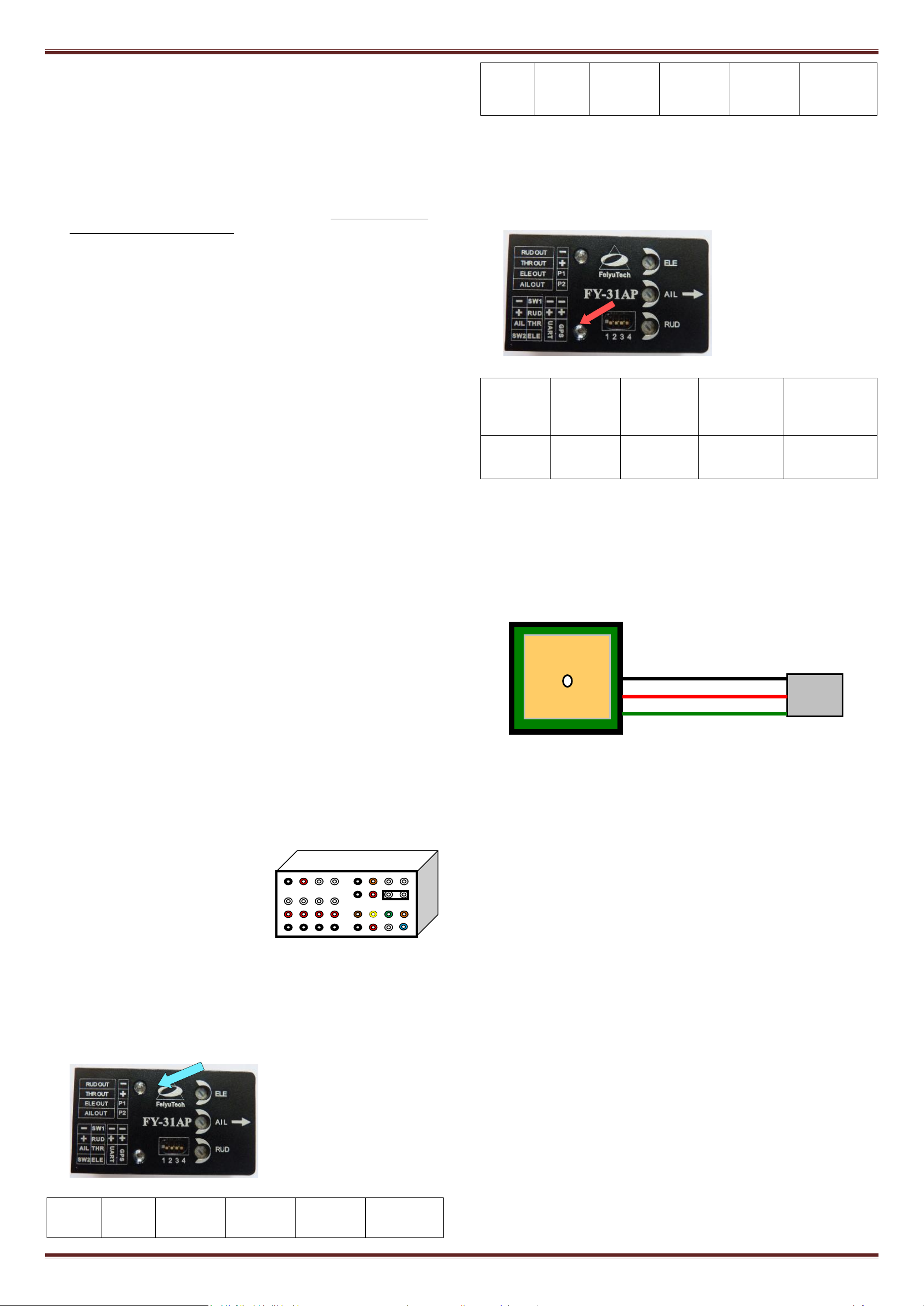
14. GPS status & vibration level indicator
You can check the GPS lock status and vibration level by observing the
Red LED.
Red light:
15. GPS Receiver
a. If GPS cannot fix the aircraft location (minimum 4 satellites), only
Mode 1 (Deactivated) and Mode 2 (Stabilized Mode) will function.
Mode 3 and Autopilot will not be functional.
b. Install the GPS Module with the antenna face up (see following
picture). DO NOT install next to metal or carbon fiber and other
shielding material, which may block satellite signal.
c. Install the GPS Module away from electromagnetic sources such as
ESC’s, power wires, servo wires and video transmitters.
GPS – Satellite Signal Lost During Autonomous Flight
GPS provides the aircraft geographic positioning, altitude, speed and
flight direction.
Only if the GPS Data is available will the FY31AP perform its
Autopilot Modes.
In case GPS signal is lost during flight , the autopilot will keep its
height and course (not lock)in automatic navigation mode ,but its
course may gradually drift. After GPS signal is regained the plane
will resume the Autopilot Mode.
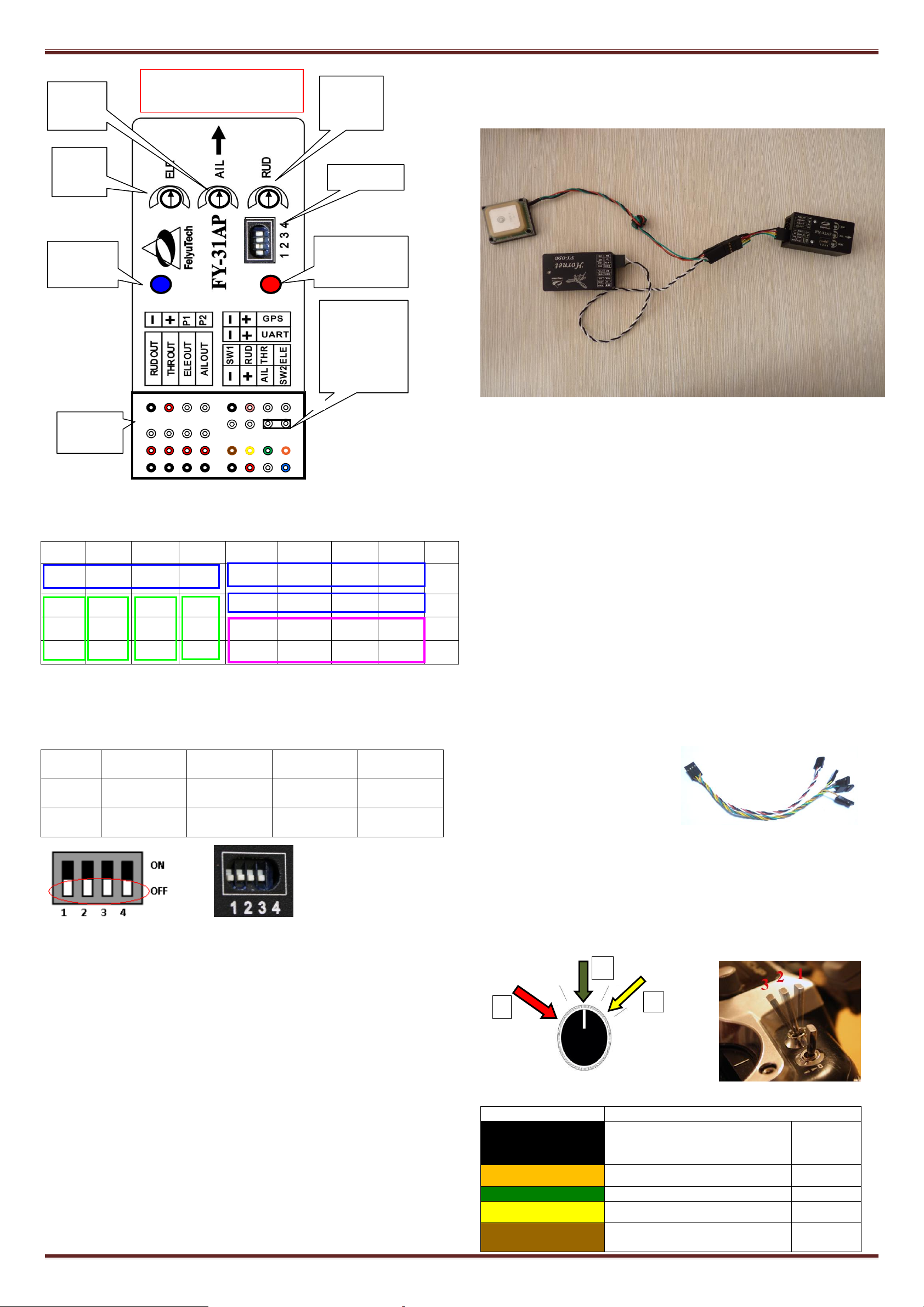
16. FY-31AP INTERFACE
13. Flight mode Indicator (Red or Blue light)
By observing the flight indicator, you can easily re-confirm your Flight
Mode switch settings of your radio.
Blue light:
Guilin Feiyu Electronic Technology Co., Ltd http://www.feiyudz.cn E-mail: service@feiyu-tech.com Page 2
Page 3
Guilin Feiyu Electronic Technology Co., Ltd
8 7 6 5 4 3 2
1
NO.
GND
Power
P1
P2
GND
3.3V
TX0
RX0
Ⅰ
RUD
THR
ELE
AIL
GND
Power
TX1
RX1
Ⅱ
Power
Power
Power
Power
Switch 1
Rudder
Throttle
Elevator
Ⅲ
GND
GND
GND
GND
GND
Power
Aileron
Switch 2
Ⅳ
Switch
number
1 2 3
4
ON
For Factory
use only
Flight Mode
Selection
Flight Mode
Selection
Adjust flight
patterns
OFF
Always OFF
position
Flight Mode
Selection
Flight Mode
Selection
Normal
mode
Wire color
Receive channel
White
(bundled with red
& black)
aileron
Channel 1
orange
elevator
Channel 2
green
throttle
Channel 3
yellow
rudder
Channel 4
brown
SW 1
Any free channel controlled by
Channel 5
1
2
3
POINT ARROW FORWARD
(TOWARDS FLIGHT DIRECTION)
2 3 4
5 6 7
8
1
Function DIP
Jumper installed
during gyro
initialization.
Do not insert
jumper during
normal use.
Red LED: the GPS
status & vibration
level indicator
Rudder
sensitivity
Aileron
sensitivity
knob
Elevator
sensitivity
knob
Blue LED:
Flight mode
indicator.
Interface pin
panel
Ⅳ
Ⅲ
Ⅱ
Ⅰ
You need a 4p Y cable, the Hornet - OSD(above firmware V1.6).
data cable and GPS module connected to the FY-31AP(above firmware
V2.1)’s GPS interface. Connection diagram is as follows:
Pin interface to sort the list
NOTE: The pin”I-1,2,3,4”is for the GPS module, “I-3”pin output
+3.3V, so please don’t supply to this pin, or will burn the
FY-31AP.
DIP Switch Function:
Note:
In this manual, the direction for all the DIP switches is shown by
white color .
the position for the DIP switch 1 is OFF, if it was put in ON, then the
FY-31AP cannot work normally.
UART Interface
The UART pin interfaces consist of: GND, power, TX1, RX1. The
characteristics are as follow:
Baud Rate: 19200
Data bits: 8
Stop Bits: 1
Parity: None
Interface features: TTL
The pin interfaces output telemetry data. This interface connects to the
data radio, PC computer serial port or OSD module. You can set the
flight route, navigation and control parameters of FY31AP by this
interface. The port is also used to upgrade FY31AP firmware.
Please read the procedure for the firmware upgrading.
FY-31AP Electrical Connection and Diagram
a) Power supply
The FY-31AP operates between 4 to 6 volts input.
FY-31AP is powered via the Receiver connection.
If your plane is Electric powered, the Receiver power supply is
normally from the ESC built-in Battery Elimination Circuit (BEC).
However, we highly recommend that a separate BEC with a 3A
output.
For Gas or Nitro powered planes, you will require a battery to power
the Receiver and FY-31AP.
b) Connections The FY31AP is
connected to your RC Receiver
via a 6 wire cable. You need a
minimum 6 Channel RC
Receiver.
FY-31AP requires a minimum
of 6-channel RC receiver.
4 Receiver channels are used for aileron (channel 1), elevator
(channel 2) ,throttle (channel 3) and rudder (channel 4) signal
output. Connect these 4 receiver output signals to the FY-31AP with
the supplied wires (pay attention to the color of each channel ).
2 free Receiver channels are required to control the FY-31AP Flight
Modes (3-position switch or dial knob, ”SW1”) and Autopilot
Mode (3-position switch or dial knob, ”SW2”).
GPS features
The FY31AP GPS pin interface consist of: GND, 3.3V voltage, TX0, RX0.
The characteristics are:
Baud Rate : 38400
Interface Features: TTL level
Data bits: 8
Stop Bits: 1
Parity: None
Connect the above to the GPS Receiver. The GPS data protocol is a
standard NEMA0183 and the statement must be $ GPRMC, $ GPGGA.
NOTE: The pin”I-1,2,3,4”is for the GPS module, “I-3”pin output
+3.3V, so please don’t supply to this pin, or will burn the
FY-31AP.
TXO pin interface is used to output FY-31AP(above firmware V2.1) data,
and connect Hornet-OSD(above firmware V1.6).
Horner-OSD can be connected to the FY-31AP high-speed data outlet.
Guilin Feiyu Electronic Technology Co., Ltd http://www.feiyudz.cn E-mail: service@feiyu-tech.com Page 3
c) Note that the wire is arranged according to color :
Page 4

Guilin Feiyu Electronic Technology Co., Ltd
3-way switch or dial knob
blue
SW 2
Any free channel controlled by
3-way switch or dial knob
Channel 6
SW-1 signal output
900-1200us
1200-1800us
1800-2100us
Functional mode
Deactivated
Mode
Auto Stabilize
Mode
Navigation
Mode
Blue LED light
indicator
continuous flash
Stay on solid
Single flash
SW-2 signal
output
900-1200us
1200-1800
us
1800-2100us
Functional
mode
Return To Launch
Mode
(RTL)
Cancel
Mode
Auto Circling Mode
(ACM)
Blue LED light
indicator
Continuous Double
flash each loop
/
Continuous flashing.
3 times each loop
AIL OUT
ELE OUT
THR OUT
RUD OUT
Aileron
Servo
Elevator
Servo
Throttle
Servo
Rudder
Servo
AIL OUT
ELE OUT
THR OUT
RUD OUT
Differential
Servo 1
Differential
Servo 2
Throttle
Servo
Rudder
Servo
AIL OUT
ELE OUT
THR OUT
RUD OUT
Aileron
Servo
Differential
Servo 1
Throttle
Servo
Differential
Servo 2
AIL OUT
ELE OUT
THR OUT
RUD OUT
Differential
Servo 1
Differential
Servo 2
Throttle
servo
Null
AIL OUT
ELE OUT
THR OUT
RUD OUT
Rudder
Servo
Elevator
Servo
Throttle
servo
Null
AIL OUT
ELE OUT
THR OUT
RUD OUT
Roll Servo
Tilt Servo
Null
Pan Servo
900-1200us Deactivated Mode
1200-1800us Auto Stabilization Mode
1800-2100us Navigation Mode
900-1200us Return To Launch Mode
1200-1800us Cancel Mode
1800-2100us Auto Circling Mode
17. Vibration damping
A. FY-31AP is vibration-sensitive. To optimize its stabilization capability,
vibrations reaching the unit must be kept at a minimum.
B. When installing this flight stabilizer, we highly recommend that you
install it with the supplied vibration absorbing pads (dampers).
C. The algorithm in the FY-31AP compensates for normal levels of flight
vibration. However, if the vibration experienced by the unit exceeds
the acceptable level, it will not work normally or may even stop
working altogether.
D. To keep vibration at a minimum, install the FY-31AP away from the
engine or any other vibration sources.
E. The included shock-absorbing pads will
meet the damping requirements for
electric powered aircrafts and most gas
/ nitro planes.
F. The FY-31AP is supplied with the
double-sided foam padding dampers.
Please use them as shown:
19. Plane connecting layout
1) FY-31AP connection for traditional aircraft layout:
2) FY-31AP connection for flying wing aircraft:
(with or without Rudder)
Checking for Vibration Levels
Even with the shock absorbing mount, your
aircraft installation may not meet the damping requirements of the FSS.
To confirm correct vibration damping, please follow this procedure:
A. After connecting all wires between the FY-31AP,Receiver and ESC,
install the unit as recommended (ensure correct orientation).
B. Run the plane engine or motor at different throttle levels. DO NOT
TAKE OFF.
C. Move the throttle level to different positions and maintain it for 20
seconds at each position.
D. At each throttle position, observe the state of the red LED light. If it
stays OFF, that means your vibration level is acceptable.
E. If instead the red LED lights up bright and stays ON solid, then the
vibration dampening is not enough. You will need reduce the level of
vibration on your aircraft, add additional dampening support or
change the installation location.
18. SW 1 and SW 2 : Switch Settings for FY31AP
a. SW-1 Flight Modes
The FY31AP has 3 Flight modes
controlled via SW-1. To select the modes,
use a free Receiver channel controlled via
a 3 way-switch:
FY-31AP flight modes
3) FY-31AP connection for V tail aircraft with Aileron:
4) FY-31AP connection for V tail aircraft without ailerons:
5) FY-31AP connection for traditional layout aircraft with no Aileron:
Note: Navigation Mode: means one of the three modes. Path Navigation mode,
Fixed altitude flight mode and Heading lock flight mode. You can select via the
GCS Software. The default mode is Path navigation mode.
b. SW-2 Autopilot Modes
FY31AP Autopilot Modes is controlled via SW-2.
IMPORTANT: The Autopilot Mode (SW-2) has controlling priority
over the Flight Modes (SW-1). If you wish to use the Flight Mode
(SW-1), you must de-activate the Autopilot first.
6) Camera Gimbal Stabilization:
* Note: The camera gimbal Roll, Tilt and Pan servos will counter any
linear movement of the camera mount. You can move the camera at any
angle and upon releasing the stick, the FY-31AP will maintain
stabilization at that angle. The FY-31AP is only suitable for the camera
gimbal control which the control accuracy is not very high.
20. Connection of FY-31AP
Guilin Feiyu Electronic Technology Co., Ltd http://www.feiyudz.cn E-mail: service@feiyu-tech.com Page 4
Page 5

Guilin Feiyu Electronic Technology Co., Ltd
Right aileron
automatically
move downwards.
Roll right
Left aileron
automatically
move upward.
Right aileron
automatically
move upwards
Roll left
Left aileron automatically
move downwards
Aileron Movement In Auto Stabilization Mode
The 3 dials control
both gain & servo
direction.
+100 Max
-100 Max
0 Min
Plane nose will pitch
down when in Auto
Stabilization Mode.
Plane nose pitches up when
in Auto Stabilization Mode.
Plane pitch remains
level when in Auto
Stabilization Mode
FY-31AP
Plane will roll to the
left when in
Stabilized Mode
FY-31AP
Plane roll remains level when in Auto Stabilization Mode
FY-31AP
FY-31AP will roll to
the right when in
Stabilized Mode
Max Gyro Gain
Max Gyro Gain
Servo direction
change in
Mode 3 & 2.
Servo direction
change in
Mode 3 & 2.
12 O’clock
Min Gyro Gain
OSD
Module
THR OUT
ESC
AIL OUT
RUD OUT
ELE OUT
Battery
Brown
Green
Blue
Yellow
Red
Black, red, white
RC receiver
GPS
Module
Electric
Motor
Data Radio
1. There are 3 adjustment dials on the FY31AP. Each dial controls both
gyro gain
and
servo direction during auto stabilization.
21. FY-31AP installation: Orientation, Position and level
a) The FY-31AP has an arrow printed on the top of it. Orientate the
arrow towards the front of the craft (i.e. direction of flight).
b) When installing, please keep the FY-31AP horizontal and as close as
possible to the "Centre of gravity" (COG) of the aircraft.(as the
following diagram)
c) The control benchmark of FY-31AP is the NEUTRAL VALUE position.
But when install the dip angle between FY-31AP and the plane still
should be not more than 15 deg .
d) If there is deviation between the neutral value position and the
plane’s level flight, it may cause deviation of fixing plane’s level
flight. See next topic. But these deviation can be amend by recording
the neutral value. Please refer “RECORDING YOUR AIRCRAFT
NEUTRAL VALUE.”
2. Gyro Gain: The further away from Centre (12 O’clock) the higher
the Gyro gain (sensitivity). Too low gain result is poor auto
stabilization, too high gain will cause oscillations of the aircraft. You
need to adjust the gain setting based on the requirement of your
aircraft.
3. Servo Direction: The dials also control the direction of your servo
movement. Turning it clockwise or counter clockwise from 12
O’clock will change the direction of your servos during stabilized
flight against tilting, roll and yaw.
23. CONTROL SURFACE MOVEMENT CHECK
Install FY31AP as recommended in this manual, then proceed to confirm
correct control surface movement direction in Mode 2 or Mode 3.
1. In Manual mode (stabilization deactivated) confirm that the control
surfaces do to react when your aircraft is tilted or rolled.
2. Activate Mode 2 (Auto stabilize mode) and observe the movement
direction of Aileron, Elevator and Rudder. The direction should be as
shown below. If direction is wrong, turn the appropriate dial to the
opposite side of 12 O’clock to get the action direction correct:
AILERONS - Roll the plane to see the following action:
Incline the plane to the right (roll right). The ailerons should give a
control signal to counter this roll direction (see below). Same as when
rolled to the left. If the ailerons move correctly, the knob has been
turned in the right direction. You can now adjust gain by moving
nearer (low gain) or further away (high gain) from center;
If the ailerons do not follow the movements shown above, simply turn
the aileron knob to the opposite side (beyond centre). You should
now see the correct aileron movement.
22. Adjustment Dials for ELE, AIL and RUD
Guilin Feiyu Electronic Technology Co., Ltd http://www.feiyudz.cn E-mail: service@feiyu-tech.com Page 5
Page 6

Guilin Feiyu Electronic Technology Co., Ltd
Rudder moves
to the left
Rotate right
Rotate left
Rudder moves
to the right
Rudder Movement Auto Stabilization Mode
Elevator Movement In Auto Stabilization Mode
Elevator moves up
Nose Down
Elevator moves down
Nose Up
ELEVATOR - Pitch the plane nose up and down to see the following
elevator action:
Incline the plane NOSE UP. You should see the elevator move down.
And when you move the NOSE DOWN, the elevator should move up.
Move the Elevator knob to the opposite side (from Centre) if the
servo movement is incorrect.
RUDDER - Turn your plane clockwise or counter clockwise to see the
rudder movement below:
Move the Rudder knob to the opposite side (from Centre) if the servo
movement is incorrect.
Adjust Rudder gain according to your aircraft requirement (lowest
gain nearest to centre, highest gain further away from centre).
links. Re-confirm that your aircraft is perfectly level. This is your
aircraft Neutral position.
Step 5: While in Step 4 leveled position, activate Mode 3 (Auto
Stabilization Mode) for at least 2 seconds. Since Dip Switch No. 4 is
ON, the FY31AP will now record the Neutral Point.
Step 6: After 2 seconds, move Dip Switch No. 4 back to OFF position.
The procedure is complete and the system is ready for flight.
Note: when the DIP Swith NO.4 is in the ON position,the FY-31AP will
record the neutral point for each time you switch the mode from Mode
1: Deactivated Mode to Mode 2: Stabilized mode.
25. Checking the control surface & LED before fly
Before your fly please reconfirm correct control surface movement
direction both in RC control mode(Mode 1) and Stabilized
mode(Mode2).
Switch the SW1 and SW2, to observe if the blue LED flash in the
correct way in each mode.
Observe the Red LED to confirm if the GPS have locked, if yes, then
you can take off your plane.
26. Stabilized mode (Mode2)Test And Sensitivity Adjustment
24. RECORDING YOUR AIRCRAFT NEUTRAL VALUE
1) The FY31AP can record your aircraft best stabilization attitude in its
memory. By recording this ‘Neutral Value’, the FY31AP can know
how best to control your aircraft for optimum stability.
2) You can do this procedure with the aircraft on the ground or in the
air.
3) Setting the Neutral Value on the ground is quick and easy and will
produce good stabilization results. However recording neutral value
‘on the fly’ will result in more accurate autonomous flight attitude
control.
Recording Neutral Value on the Ground
Step 1: Set up your aircraft and ensure correct FY31AP orientation,
position & leveling. Ensure the Mode 3 (auto stabilization) Elevator,
Aileron and Rudder movements are in the correct direction.
Step 2: Move Dip Switch No. 4 to ‘ON’ position.
At this stage, your aircraft should already have automated surface
control with the right direction when in Auto Stabilized Mode and
the Neutral Value is already recorded.
Now you need to fine tune your FY31AP stability gain via flight tests.
For the first flight it is recommended that the gains not be set too
high. To avoid excessive oscillation (flight overcorrection) put the
gyro gain at mid point.
Take off in Mode 1 (Manual Mode). After achieving safe height,
activate Mode 3 (Auto Stabilized).
Aileron Gain: If you see oscillation of the wings, this indicates the
Aileron gain is set too high. Switch back to Mode 1 and land the
airplane.
Reduce the sensitivity (move dial towards centre position) and fly
again. You should see improvement in wing attitude. Adjust until
you are satisfied with the level of wing stabilization.
Elevator & Rudder Gain: Too much Elevator gain will show the tail
moving up and down (nodding). Too much Rudder gain will show
tail wagging. Reduce gain until this flight over corrections
disappears.
Alternately, if you find the flight correction is not enough (too low
stability), you can increase gain accordingly.
27. Recording Neutral Value ‘On the Fly’
After the checking for the control surface, adjust the 3 knob switch to a
suitable position(advice to adjust for about half),then you can test the fly
now. The test for fly is in order to record the neutral value ‘on the fly’.
This can help you get more accurate autonomous flight attitude control.
It is best to carry out this procedure during minimal wind conditions.
Step 1: Set up your aircraft and ensure correct FY31AP orientation,
position & level. Ensure the Mode 3 (auto stabilization) Elevator, Aileron
and Rudder movements are in the correct direction.
Step 2: Move Dip Switch No. 4 to ‘ON’ position.
Step 3: Place your aircraft on a table. Arrange the aircraft so that is
perfectly level. Position the aircraft exactly as you wish it to be during
auto stabilization flight (i.e. fuselage and wings perfectly level).
Step 4: ON your transmitter and zero all your trims. Power up the
FY31AP in Mode 1 (Manual Mode). Confirm there are no deflection
to the Aileron, Elevator and Rudder surfaces by adjusting your servo
Guilin Feiyu Electronic Technology Co., Ltd http://www.feiyudz.cn E-mail: service@feiyu-tech.com Page 6
Step 3: ON your transmitter and zero all your trims.
Confirm there are no deflection to the Aileron,
Elevator and Rudder surfaces by adjusting your
servo links.
Step 4: Power ON the aircraft with the FY31AP in Manual Mode.
Step 5: Fly your aircraft to a safe height (still in Manual mode) and fly in
a Level and straight line.
Step 6: While in this Neutral Value, activate Mode 2 (Auto Stabilization
Mode) for at least 2 seconds. Since Dip Switch No. 4 is ON, the FY31AP
will now record your Neutral Value. After 2 seconds, switch back to
manual mode or keep in the Mode 3 (Auto Stabilization Mode)and land
Page 7

Guilin Feiyu Electronic Technology Co., Ltd
your aircraft.
(Note: Do not switch from Mode 1( Deactivated Mode) to Mode
2(Stabilized mode)for the second time, because when the DIP Switch
NO.4 is in the ON position, the FY-31AP will record the neutral point
each time you switch the mode from Mode 1 to Mode 2.)
Step 7: After landing, move Dip Switch No. 4 back
to OFF position. Procedure is complete.
IMPORTANT NOTE: As long as there are no major
changes in your aircraft hardware (e.g. no shifting of
Centre of gravity, ”CoG”) your Neutral Value will
not change. If there are major changes in hardware or your CoG have
shifted, it is best you repeat this Neutral Value recording procedure.
Note: if you have data radio, you also can use the GCS software to
record the neutral value ’on the fly’ more easily! The detail please
refer the manual of GCS software operate manual.
28. Test for the Autopilot mode 2: Auto Return To Launch(RTL)
After test well the stabilized mode, please keep the throttle at the
cruising position,then switch the SW2 to the Autopilot mode 2(RTL),
then the plane should return to the home point, and circle after it reach
the home point. If this test successfully, then you can switch to the
stabilized mode fly the plane to a farther distance to test the RTL again.
29. Test for the Autopilot mode 3: Auto Circling Mode (ACM)
After you complete the test for the RTL mode, you can test the ACM
mode now. Please keep the throttle at the cruising position, switch the
SW2 to the Autopilot mode 3(ACM), then the plane should circle, the
centre of the circle is the current point when you switch.
30. Test for the Model 3: Path Navigation mode
First, please connect the FY-31AP with the GCS, detail please refer
the
FY-31AP Path Navigation & GCS manual.
Set the waypoints. The most qty is 8 waypoints(above firmware V2.1,
waypoints add to 20. ). Then switch into the path navigation mode
for the waypoint fly.
Don’t forget to keep the throttle at the cruising position .
When you switch into the path navigation mode, to observe if the
plane fly according the path you set.
The default path navigation in FY-31AP is auto repeat .when the
plane fly over the last waypoint it will fly back to the first waypoint.
You can cancel this default value via the GCS software, then the
plane will not fly back, just circle in the last waypoint.
More about the path navigation fly please refer to the manual
Path Navigation & GCS.
FY-31AP
——END——
Note: We reserve the right to change this manual at any time! And the
newest edition will be shown on our website www.feiyudz.cn.
Guilin Feiyu Electronic Technology Co., Ltd http://www.feiyudz.cn E-mail: service@feiyu-tech.com Page 7
 Loading...