

Page 1

Gibbs and Associates
323 Science Drive
Moorpark, CA 93021
(805) 523-0004
March, 1999
SOLIDSURFACER
ADDENDUM
Page 2

◆
SolidSurfacer Addendum GFK-1710
Proprietary Notice
This document contains propriety information of Gibbs and Associates and is to be used only pursuant to and in conjunction with the license granted to the licensee with respect to the accompanying Gibbs and Associates licensed software. Except as expressly permitted in the license, no part of
this document may be reproduced, transmitted, transcribed, stored in a retrieval system, or translated
into any language or computer language, in any form or by any means, electronic, magnetic, optical,
chemical, manual or otherwise, without the prior expressed written permission from Gibbs and
Associates or a duly authorized representative thereof.
It is strongly advised that users carefully review the license in order to understand the rights and
obligations related to this licensed software and the accompanying documentation.
Use of the computer software and the user documentation has been provided pursuant to a Gibbs
and Associates licensing agreement.
© Copyright 1999 Gibbs and Associates, Inc.
All Rights Reserved
Acknowledgements:
Written by Wil Gaffga
Thanks to Bill Gibbs, Shannon McConville, Steve Aughinbaugh, Bart Ehlers, Gary Esser, Israel
Klain, Alvaro Martins and Vincent Schmidt for their input, advice and assistance.
Trademarks:
Windows NT and Windows 95 are trademarks of Microsoft Corporation
Printed in the United States of America
Page 3

Table of Contents
INTRODUCTION 1
INTERFACE 1
File Extension Preferences . . . . . . . . . . . . . . . . . . . . . . . . . . . . . . . . . . . . . . . . . . . . . . . . . . .1
Select Sub-Menu . . . . . . . . . . . . . . . . . . . . . . . . . . . . . . . . . . . . . . . . . . . . . . . . . . . . . . . . . .1
MODELING 2
Sweep Dialog ...............................................................2
DATA EXCHANGE 5
Direct Open of Native File Formats .............................................5
IGES Surface Export .........................................................6
Improved SAT Import .........................................................6
MACHINING 8
CAM Engine Tab ............................................................8
Surfacing Operations . . . . . . . . . . . . . . . . . . . . . . . . . . . . . . . . . . . . . . . . . . . . . . . . . . . . . .12
2.5D Material Only . . . . . . . . . . . . . . . . . . . . . . . . . . . . . . . . . . . . . . . . . . . . . . . . . . . . . . .16
Machining Open Sided Pockets . . . . . . . . . . . . . . . . . . . . . . . . . . . . . . . . . . . . . . . . . . . . . .11
SOLIDSURFACER TUTORIAL NOTES 20
MACHINING EXERCISES 21
Exercise #1 : Phone . . . . . . . . . . . . . . . . . . . . . . . . . . . . . . . . . . . . . . . . . . . . . . . . . . . . . . .21
GFK-1710 T able of Contents
◆
1
Page 4
Introduction
This addendum details the additions to the system contained within v. 5.0. It is solely a supplement
to the SolidSurfacer manual. This addendum does not include Geometry Creation, Lathe, Mill,
Rotary Mill or Advanced Milling functionality.
Interface
This section describes the changes to the interface. The system has adopted modifications to the
Select sub-menu and an expanded File Extension preference.
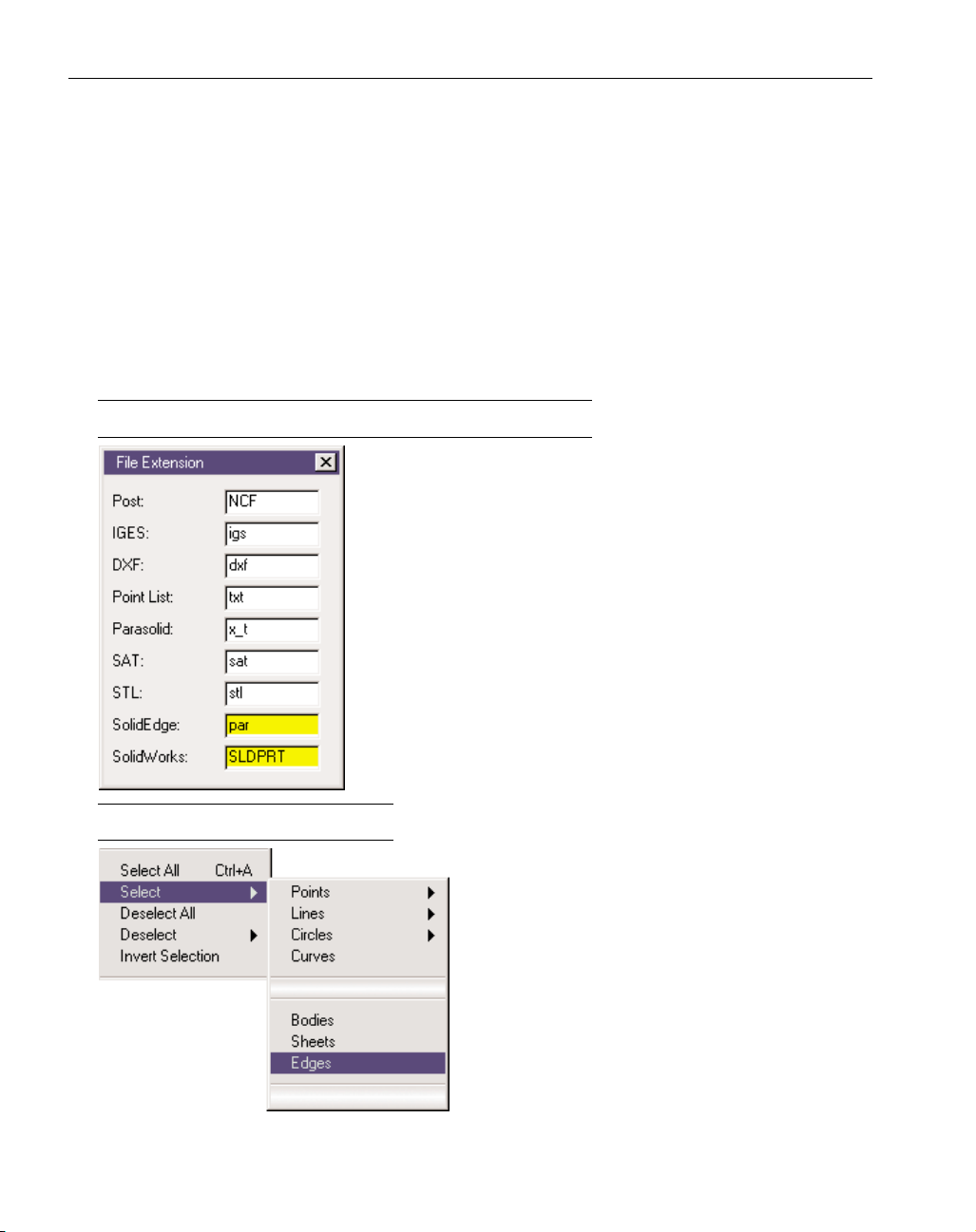
FILE EXTENSION PREFERENCES
The File Extension Preference has been modified to include
SolidEdge and SolidWorks files. This is to accommodate the new
capability of directly opening these files. (See the Data Exchange
section of this document for more information.)
SELECT SUB-MENU
The user may now automatically select all edges
on an active body. This capability is accessed from
the Select sub-menu of the Edit menu. Any edges
that the user does not wish to have active may then
be de-selected.
2
◆
SolidSurfacer Addendum GFK-1710
Page 5
Modeling
This section describes the changes to modeling functions in the SolidSurfacer module.
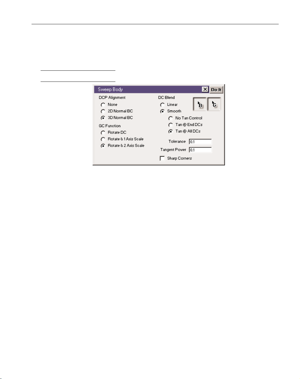
SWEEP DIALOG
Drive Curve (DC) Blend: The user is given control over transitions between Drive Curves. Used when
there are more than two Drive Curves.
Linear Blends will produce the same result as if the sweep was performed on the sections separately. As if the results of a sweep between DC1 and DC2 were added to the results of a sweep
between DC2 and DC3.
Smooth Blends: A smooth continuous body will be swept between the drive curves as specified
by the option selected.
No Tangent Control: There will simply be a smooth transition between Drive Curves. The
user has no control over tangency.
Tangent at End DCs: The swept body will be blended to be tangent to the Base Curve at the
first and last Drive Curve. Transitions between any other Drive curves will be smooth
without any control, as with No Tangent Control.
Tangent at All DCs: The swept body will be blended to be tangent at all Drive Curves.
Tangent Power: Tangent Power controls the strength of the tangent blending when specifying
control for the ends or all Drive Curves. The range is from 0.0 (no control, works the same as
No Tangent Control) to 1.0 (a very sharp transition with long straight parallel sections.
3
GFK-1710 SolidSurfacer Addendum
◆
Page 6
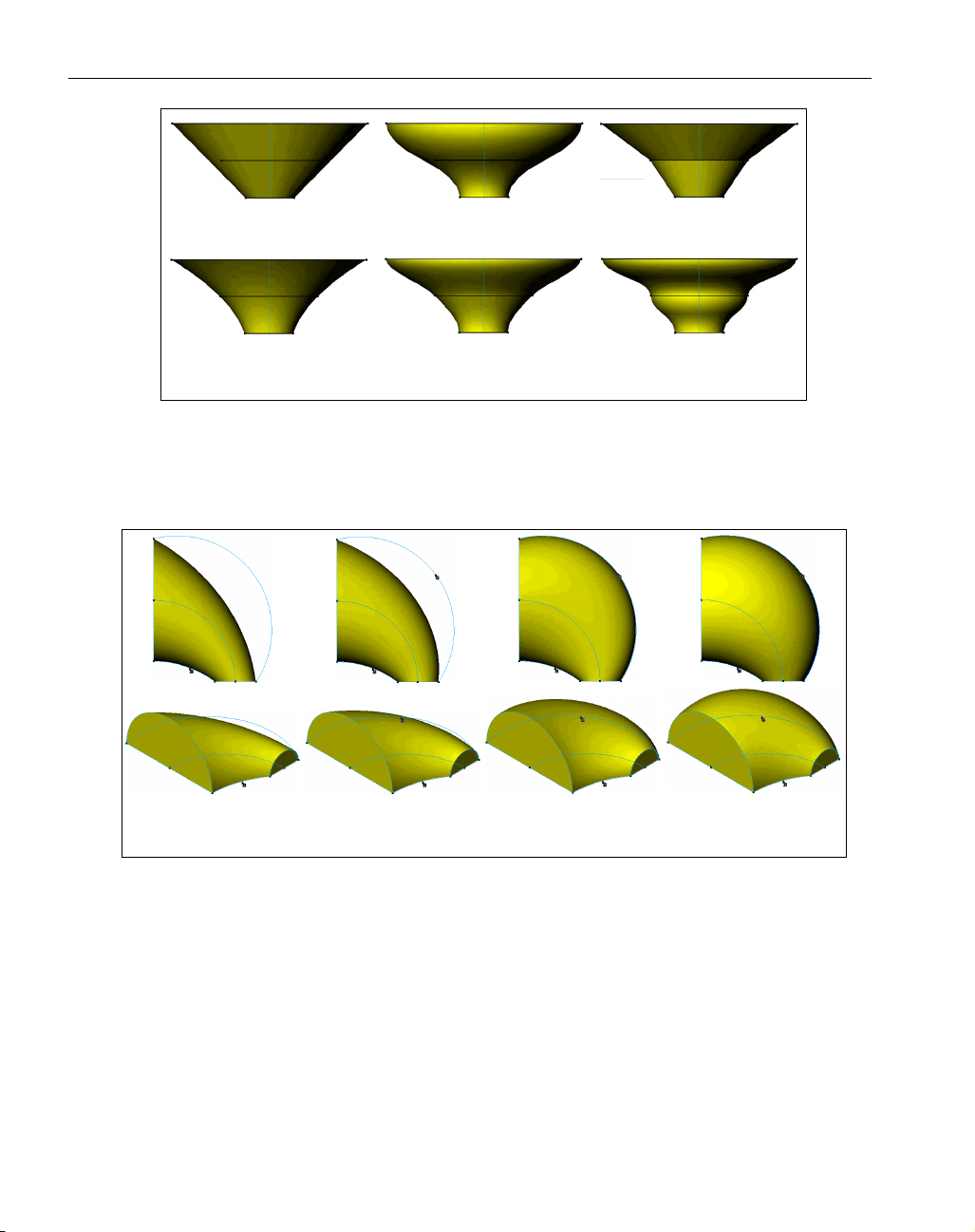
Figure 1: Examples of swept Bodies with 1 Base Curve
Guide Curve (GC): This is an optional curve that can be used to control alignment of the Drive Plane,
replacing the “normal-to-Base-Curve” standard. It can also be used to “scale” the Drive Curve in
one or more axes.
Figure 2: Examples of swept Bodies with a Base Curve and a Guide Curve
Sharp Corners: This button toggles on or off whether corners should be smooth (rounded) or sharp,
(square). If Sharp is chosen the system will extend a body so the corners meet to have mitred corners, keeping the drive curve’s profile.
4
◆
SolidSurfacer Addendum GFK-1710
2 Drive Curve
Linear
3 Drive Curve
No Tangency
2 Drive Curve
Tangent
3 Drive Curve
Tangent @ Ends
3 Drive Curve
Linear
3 Drive Curve
All Tangent
1 Base Curve Base Curve & Guide Curve
Rotate Only
Base Curve & Guide Curve
Rotate & 1 Axis Scale
Base Curve & Guide Curve
Rotate & 2 Axis Scale
Page 7
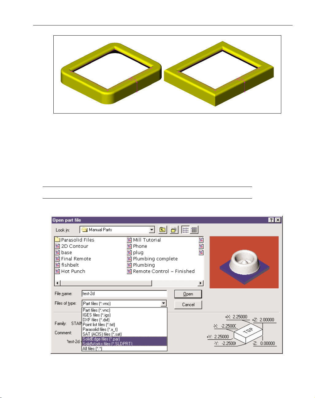
Figure 3: Example of Rounded versus Sharp corners. Note that even the interior corners are sharp
or smooth.
Data Exchange
This section describes the new capabilities and improvements to the Data Exchange capabilities of
the system.
DIRECT OPEN OF NATIVE FILE FORMATS
The system now has the ability to directly open and read SolidWorks and SolidEdge (v.5.0 or later)
native file formats.
5
GFK-1710 SolidSurfacer Addendum
◆
Page 8
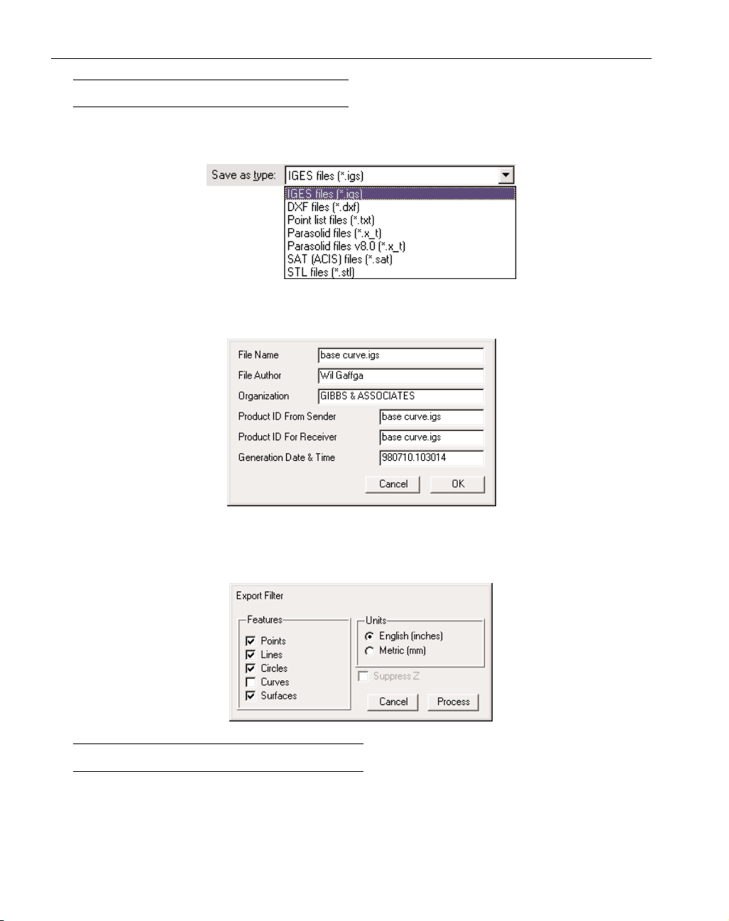
IGES SURFACE EXPORT
The system can now export geometry and bodies as IGES surface entities. From the File menu
select Export. This will bring up the standard Open/Save dialog. Select IGES files from the Save as
Type pull down menu..
Once the file is named and Save has been clicked the following dialog will come up. The information may be altered as needed by the user.
When OK has been clicked the Export Filter dialog will come up. This allows the user to define
what elements are to be exported and the measurement unit to be used. When the Process dialog has
been pressed the system will compile the IGES file and save it as directed.
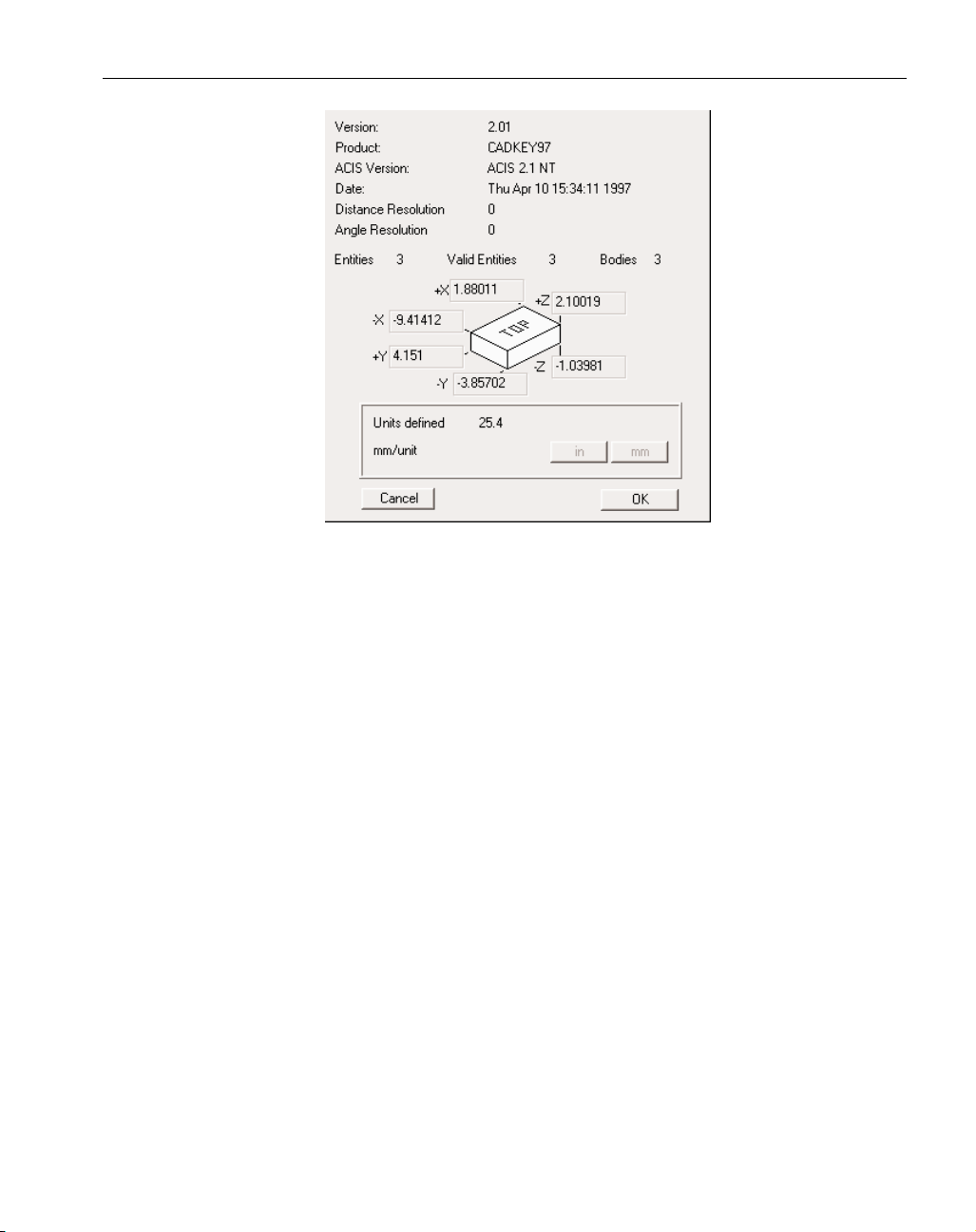
IMPROVED SAT IMPORT
SAT files may either be directly opened or they may be imported into a .vnc file. Importing a file
offers the advantage of being able to bring in more than one file. The system will read the SAT file
to determine what it is and where it came from. This information is contained within the file’s header and will be displayed as seen in the following image. Older versions of these files do not have
this header information. Whatever information can be determined will be displayed in the dialog.
6
◆
SolidSurfacer Addendum GFK-1710
Page 9
7
GFK-1710 SolidSurfacer Addendum
◆
Version: This is the SAT version that output the ACIS file. Earlier numbers mean older SAT files.
Product: This is the CAD product used to create the SAT file.
ACIS Version: This is the version of ACIS the file was saved as.
Date: This is the date on which the file was created.
Distance Resolution: This is the distance (not in measurable units) between which any two points are
coincident.
Angle Resolution: The minimum determinable angle value based on distance resolution and measure-
ment units.
Entities: The total number of entities contained in the file. This can be just bodies or it can be bodies
as well as extraneous information.
Valid Entities: The total number of valid entities the system can read, this may include invalid bodies.
Bodies: The total number of bodies ACIS considers valid.
Size Specifications for the Part Model: SAT files are written in generic units. It is not defined whether
these units are millimeters, inches or meters.
User Defined Units: The user is asked to define a conversion value for mm per unit. If the units are
inches enter 25.4 mm/unit. Clicking on the in button will automatically enter this value in the conversion box. Be sure that the unit of measure for a part is the same as that designated in the
Document Control Dialog. If you do not know the original units of measure, make an estimate
based on the units shown in the dialog. This section will be grayed out if the units are specified in
the header.
Page 10

8
◆
SolidSurfacer Addendum GFK-1710
Machining
This section describes the changes to the machining capabilities of SolidSurfacer.
POCKETING
STOCK DEFINITION
Due to improvements and new functionality in the system, the stock condition for pocketing in
SolidSurfacer is now critical. A part should be fully included (part plus Surface Stock) within the
stock. Error messages related to this are shown below.
2D OPTIMIZE OPTIONS
The system now has multiple options on which toolpath generation engine to use in Contour or
Pocketing operations. This gives the user more control over the results of toolpath generation. A
brief summary of 2D Optimize is given below but for a more complete understanding of this topic
see pages 193-195 or 199-200 of the SolidSurfacer manual.
Typical 3D toolpaths are thousands of small line moves. The purpose of the 2D Optimize option is
to produce ideal line and circle toolpaths from what might otherwise be a 3D toolpath.
2D Optimize is useful when a solid or single surface is being machined. The selected faces of a feature must be stitched together into a single surface. 2D Optimize should only be used to machine a
collection of surfaces if each surface is a single feature. That is, if for example, each of the surfaces
was a single pocket.
Page 11
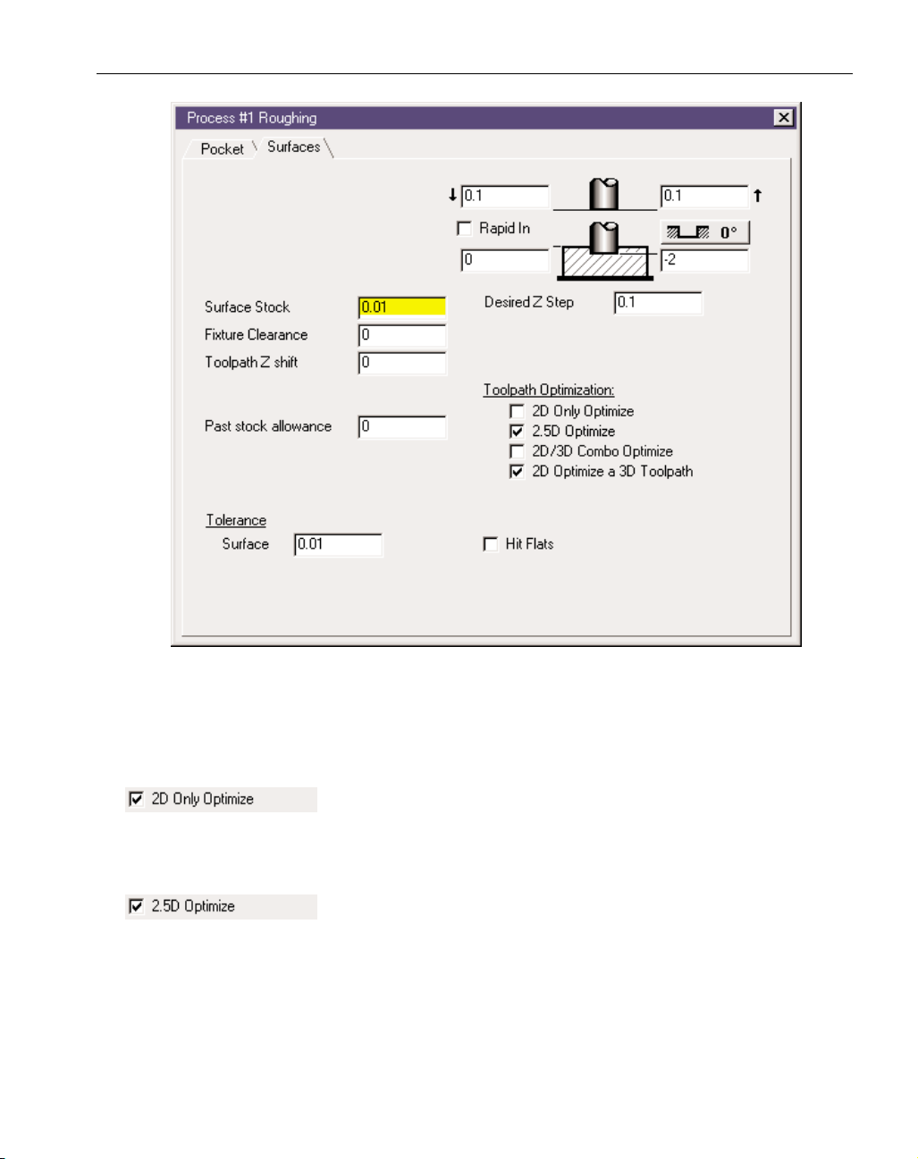
Any combination of the Toolpath Optimization options may be chosen. The system will start with
the most simple and quick, try to generate toolpath, then move down the list to the next option if
optimization fails. For example, in the previous image the system would run the 2
1/2
D Optimize then
move to the 2D Optimize a 3D Toolpath.
This option generates toolpaths very quickly. This option will generate
2D toolpaths without surface tolerance if all selected faces are 2D. 2D
Only Optimize does not provide for undercut protection. See the Solid Surfacer manual for more
information about this option.
This option will work on all selected faces, 2D, 2
1/2
D and 3D faces but
only 2 and 2
1/2
D faces will produce optimized toolpath without surface
tolerance. For this option to work, all selected faces must be able to offset by the tool’s corner radius
amount. If the selected faces fail to be offset by the tool’s corner radius the optimization will not
work. The offsetting of faces fails when a face has an inside (concave) curvature smaller than the
offset amount or when there are faces smaller than the offset amount at an inside corner between
faces. If 2
1/2
D Optimize succeeds in its offset calculation it will generate all toolpaths and will skip
subsequent optimizations. This option does not provide for undercut protection.
9
GFK-1710 SolidSurfacer Addendum
◆
Page 12
The 2D/3D Combo Optimize checks to see if the selected faces have a
2D range on top with a non-2D range toward the bottom. This option
will produce a combination of 2D and 3D toolpaths. First there will be a 2D range down to a depth
where 3D toolpaths will be needed. 2D Only optimize will be used to within the tool’s corner radius
in Z of of the start of the 3D range. 3D toolpaths will be generated from this Z level down. This
may produce some 3D toolpaths on 2D faces near the transition area in Z but this is safer than gouging the part. This option works best with single pockets as opposed to a large and complex group of
faces that may transition from 2D to 3D at different Z depths in different areas. This option can significantly reduce toolpath generation time as the 2D Only Optimize is extremely fast.
This option only looks at 3D toolpaths. It does not generate any tool-
paths, it only seeks to improve them. 2D Optimize a 3D Toolpath will
check to see if any 3D toolpaths were generated from 2D faces. If so it attempts to replace a section
of the 3D toolpath with a 2D toolpath. This optimize does a good job of cleaning up slow 3D toolpath where 2D and 2
1/2
D faces have failed.
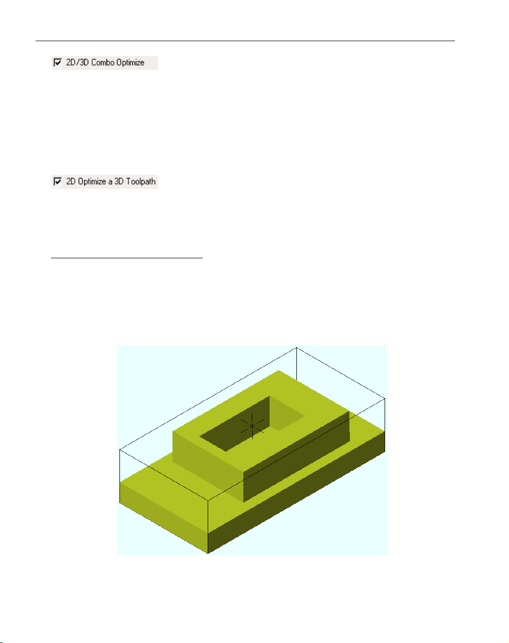
MACHINING OPEN SIDED POCKETS
The system now has an enhanced ability to machine open sided pockets. This ability as it relates to
geometry is fully detailed in the Production Addendum (page 11). With SolidSurfacer, geometry
does not necessarily need to be created or defined as “air” for this function to work The part’s stock
will function as “air” geometry and bodies function as “wall” geometry.
The following example helps to illustrate machining open sided pockets. A model is created with a
base, an island and a pocket inside the island.
To machine this model a pocketing process will be created along with drilled entry holes. This will
all be done from one routine. The routine will consist of three operations: a hole operation, and two
pocketing operations. Note that the toolpath extends to and rides on the stock diagram.
10
◆
SolidSurfacer Addendum GFK-1710
Page 13
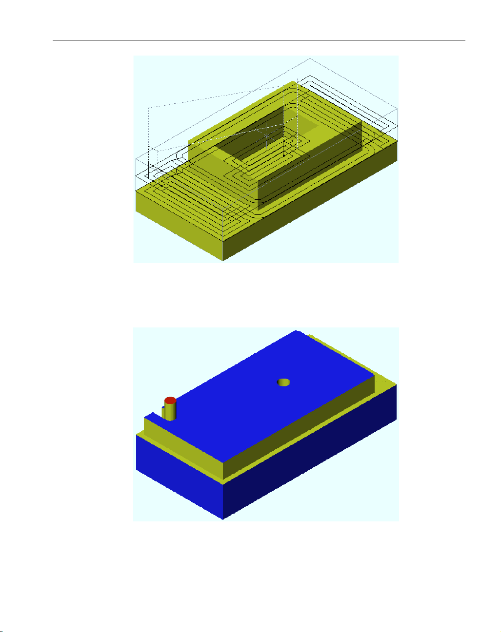
When the operation is rendered we see that only one entry hole is drilled, that being for the pocket
that is bounded by the model. The model acts as a “wall” to the operation. Thus the tool will start at
the center and work its way outward. In this image we also see that the outer pocket, which has no
boundary, only “air”, has been started from an edge and the tool is working inward.
Once the open-sided pocket is complete, the system moves on to the bounded pocket. Note that this
operation is machining outward.
11
GFK-1710 SolidSurfacer Addendum
◆
Page 14

SURFACING OPERATIONS
Fixture Clearance: A Fixture Clearance value may be defined in
Surfacing operations. This is the distance from a fixture at which
the tool will retract and rapid over a fixture, then feed back down onto the part and continue cutting.
A fixture may be defined as a body designated as a fixture, a face designated as a fixture and unselected faces on a body being machined.
CAM ENGINE TAB
SECOND GENERATION ENGINE
There is a new tab in the Process dialog referred to as CAM Engine. This tab provides access to a set
of radio buttons labeled First Generation Engine and Second Generation Engine.
The First Generation Engine is the standard toolpath generator SolidSurfacer has always had. The Second Generation Engine is a newer toolpath generator that is still being fully explored and implemented. The Second Generation Engine is not functional for all Surfacing operations at this time but will be in future releases. It is included because it is faster in certain situations or can provide a shorter toolpath. The toolpath generated by the Second Generation engine may not be visibly differ-
12
◆
SolidSurfacer Addendum GFK-1710
Page 15

ent from the First Generation engine at other times, it will look quite different. Primarily it is
designed to produce a better, cleaner, more accurate toolpath. It is highly recommended that users
set the Second Generation Engine as the default choice for creating toolpaths.
When Second Generation Engine is chosen the system will attempt to use this toolpath generator,
however, in some cases the system will seamlessly revert to the First Generation Engine. There is a
dialog next to the radio buttons that will inform the user as to the active toolpath engine based on
the type of Surfacing operation to be performed.
flow and Intersections operations are still handled by the First Generation engine. The Second
Generation Engine is currently effective for creating 2-Curve Flow and Lace Cut operations. Not all
Lace Cut variations are enabled however. The Lace Cut variations that are enabled are:
Constant Z Rough, cut Surfaces
Z Surfaces Offset Rough and both of its options, Constant Z Shift and Constant # of Passes.
One Finish Pass on Surfaces and one of its three options, All Surfaces
Any Stepover Retract Options, Retract Clearance Plane choices and Toolpath Options will be valid
choices for the Second Generation Engine. Should any of the other Lace Cut options be chosen the
system will automatically switch to the First Generation Engine. Figure 4 illustrates the valid Lace
Cut options for the Second Generation Engine. Valid choices are shown in black while the items
highlighted in gray illustrate what will be used by the First Generation Engine.
Figure 4: Illustration of Lace Cut options for Second Generation Engine.
13
GFK-1710 SolidSurfacer Addendum
◆
Page 16

GEN2 LACE CUT
For the most part GibbsCAM has kept the visible differences between the first generation engine
and the second generation engine at a minimum for an ease of transition. However, the behavior of
lace cuts is different. One of the most apparent differences is that in Gen2 operations the toolpath is
automatically trimmed to the stock. Gen1 did not do this. Another large difference is that Gen1 did
not recognize vertical walls, Gen2 does. The biggest difference is that the Gen2 engine has incredible gouge protection. You may notice a connect move in the toolpath that is neither a straight line
nor a projected line but a combination of the two. This is the Gen2 engine maximizing gouge protection but keeping the toolpath short.
Due to the gouge protection, a toolpath that is coincident with the stock boundary may retract to a
higher Z and continue cutting. Try adjusting the stepover to move the toolpath off of the part's edge.
Adjusting the Past Stock allowance and the Surface Tolerance can also help.
Don't Extend Toolpath: The tool will only move to the edge of
the part's selected faces. When it reaches unselected faces the
tool will retract and rapid to where the toolpath continues.
Extend Toolpath to Stock: The tool will move so that its tip or
center is coincident with the edge of the stock.
Extend Toolpath Clear of Stock: The tool will move a full diameter
past the stock boundaries.
The Gen2 engine will automatically cut past all edges on a part. This includes
edges between two selected faces and mixed faces (selected and unselected
combinations). The results of Cut Over Edges with Don't Extend Toolpath are slightly more complex. Some variations on machining at vertical walls are detailed below.
SURFACE FLOW CUT
Start Point: The control over the start point for Surface
Flow operations has been improved by using the Climb
checkbox and the Top Down Passes / Bottom Up Passes
radio buttons.
Cut Over Edges Off
Cut past edge, feed down and continue
Cut to edge, retract and move to new
feed location
Cut to edge, retract and move to new
feed location on edge
Cut Over Edges On
Cut past edge, feed down and continue
Cut past edge, feed down and continue
Cut past edge, retract & move to feed
into edge
Both Faces Selected
Mixed faces
Unselected Pocket
Note:
If a part has a cavity and the lowest Z level of a cut is above the bottom of the
cavity the tool will machine into the cavity to the bottom Z level. To avoid this
be sure the bottom Z cut is below the cavity depth.
14
◆
SolidSurfacer Addendum GFK-1710
Page 17

The Climb or Conventional cut is controlled by a checkbox labeled Climb. When checked the
process will be a “Climb” cut, if unchecked the system will default to a “Conventional” cut. Top
Down and Bottom Up are radio buttons thus they are toggled to one or the other. By setting these
items to how you would want to cut i.e. down or up and from the left or right side of the part, you
will get the results you are looking for. If Back and Forth is selected the climb or conventional setting will only be on the first pass. All additional passes will alternate.
2 CURVE FLOW
When using the Second Generation Engine, the system can now produce 2 curve Flow operations
based on multiple pairs of geometry. Previously, the system could only handle one pair at a time,
now there is effectively no limit to how many pairs of geometry may be used as a constraint for the
toolpath. An example is shown in the following image. Note that the top of the taller boss is deselected causing the toolpath to rapid over that section of the part.
Notes:
• On horizontal or near horizontal faces the system may not give the expected
result. Try changing the climb/conventional setting.
• A Surface Flow process is not guaranteed to be specifically climb or conventional
on the first cut. These machining parameters are only used for designating the
start location of an operation.
15
GFK-1710 SolidSurfacer Addendum
◆
Page 18

2.5D MATERIAL ONLY
Some of this information is already included in the SolidSurfacer Addendum and the Production
Release Note. The emphasis of this Material Only data is on machining Solids and is a supplement
to the data in the Production Release Note. Much of this information may be found in the
Production Release Note but is included here for ease of use.
DEFINITION
2.5D Material Only calculates toolpath for all remaining material left on walls by prior operations
only. Remaining material is stored for 2D operations; contouring, pocketing and drilling operations.
Remaining material is NOT stored for 3D operations; Lace, Surface Flow and 2 Curve Flow cuts.
Material Only supports custom stock definitions, sharp, bull nose, tapered, ball end mills and most
form tools. Undercutting tools are not supported. Material Only may be used as a single operation or
as part of a multiple process group.
DESCRIPTION
When the Material Only option is selected the system will track the areas where material is left during an operation by creating closed shapes with both “WALL” and “AIR” features or a combination
shape for each occurrence of remaining material. During subsequent operations the system will generate toolpath to remove only the material within these shapes if Material Only is selected. Toolpath
generated in these areas is based upon an open sided pocket configuration
MACHINING PREFERENCES
The Allow Mill Material Only setting must be selected
in the Machining Prefs dialog box in order for the system to track and store remaining material conditions.If
the Material Only option is not going to be used in
operations it is strongly recommended that this option
be deselected.
When this preference is on, the system will perform the
calculations needed for a Material Only operation even
if the calculations will not be applied. This information
will also be saved with the part file. The additional processing power and disk space that can be gained by
turning this option off when not used is significant.
PROCESS DIALOG SETTINGS
Overhang and Material Only: Overhang is the distance a tool’s
edge will move past an open boundary. The recommended value
is the tool radius. (For a more detailed explanation see
Overhang in the Production Addendum on page 45.)
16
◆
SolidSurfacer Addendum GFK-1710
Page 19

Past Stock and Material Only: Past Stock is the distance a tool’s edge
is allowed to travel into an open area to remove material. The recommended value for Past Stock is the Tool Diameter minus 2.5
times the maximum Surface Tolerance of any previous operation.
Example: The Past Stock value for a Material Only machining operation using a 0.5" diameter endmill and a prior operation with a Surface Tolerance of .005" would be: 0.5" - (2.5*0.005) = 0.4875"
MATERIAL ONLY RELATED TO CLOSED POCKETS AND OPEN POCKETS
When calculating toolpath for Material Only machining there are two different types of pockets, a
closed pocket and an open pocket. Each is briefly described below.
Closed Pockets and Material Only: A closed pocket is defined as a closed shape that is comprised of all
“WALL” features. (See Geometry Context Menus in the version 5.1 Production Addendum on page
25).
Open Pockets and Material Only: An open pocket is defined as a closed shape that is comprised of
either all “AIR” features or a combination of “AIR” and “WALL” features. This type of shape is
referred to as a combination shape or combination geometry. (See Geometry Context Menus in
Production Addendum).
There are two methods for working with an open pocket when generating toolpath for Material Only
machining, the Multiple Shapes and Combination Geometry methods.
When generating toolpath for Material Only machining using a solid body that has closed and/or
open pockets, SolidSurfacer uses the Multiple Shapes method. The Multiple Shapes method is
described below. (See Material Only on page 10 of the Production Release Notes for a description
of the Combination Geometry method).
Multiple Shapes Method: This is the recommended method for assuring the best toolpath when generating toolpath for Material Only machining. This method requires at least two shapes. The first shape
is an all “AIR” shape, which represents the stock and another shape representing the pocket as an
island. This second shape is an all “WALL” shape. Using this method the system treats the pocket as
an island inside the stock.
Notes:
•APast Stock value set too large will result in toolpath in areas where
no material is left from a previous operation, creating air cuts.
•APast Stock value set too small may result in toolpath that does not
clean up all the remaining material, leaving small amounts of material.
17
GFK-1710 SolidSurfacer Addendum
◆
Page 20

To generate these shapes, SolidSurfacer does a horizontal slice of the solid body at each Z-level cut
depth defined in the process dialog box. The all “AIR” shape is based on the stock condition at each
Z-level step and the all “WALL” shape(s) are based on the part condition at each Z-level step.
Example #1 below illustrates what the “AIR” and “WALL” shapes would look like at two different
Z-level steps.
• The first image, Image A, is the part body. The floor is at Z-zero, two walls are 1" high and
the other two walls are .375" high.
• Image B is the custom stock body. The outside is to size, leaving only the inside “pocket” to
be machined.
• Image C is an all “AIR” shape representing the stock body. Since the stock body is an
extruded shape the stock shape is the same at each Z step cut depth.
• Image D consists of two all “WALL” shapes representing the 1" high walls of the pocket.
These pocket shapes will be used when generating toolpath for all Z cut depths above .375".
• Image E contains four all “WALL” shapes representing both the 1" high and .375" high
walls. These pocket shapes will be used when generating toolpath for all Z cut depths below
.375".
Example #1: Solids and Material Only - Multiple Shapes method
18
◆
SolidSurfacer Addendum GFK-1710
1.0" high
0.375" high
Pocket Floor
at 0.0"
Image A - part body
Image C - "Air" shape
0.375" high
1.0" high
Image D - Two "Wall" shapes
They represent the 1" walls
Image B - custom stock body
Image E - Four all "Wall" shapes
They represent the 1" and .375" walls
Page 21

OPTIMIZING MATERIAL ONLY WHEN MACHINING A SOLID BODY
• Avoid full body selections. Only select the area (faces) to be cut.
• Use 2.5D toolpath optimization. This will produce better toolpath (G2s and G3s not just G1s) and
will also allow for a tighter Surface Tolerance setting. Avoid undercuts when using the 2.5D toolpath optimization feature.
• Select Ignore Tool Profile when permissible. (Note - For more information on Ignore Tool Profile
see page 5 of the Production Release Notes.)
Trouble Shooting Material Only Results:
• Tools with undercuts are not supported.
• Material Only does not support custom stock bodies with undercuts.
• The toolpath is not optimal or the tool retracts an undesirable amount due to lack of a Depth First
option:
Depth First is not supported for Material Only cuts in this release.
• Toolpath is generated where no material is left from a previous operation:
The Past Stock value for this operation is too large. Recommended value for Past Stock is
the Tool Diameter minus 2.5 times maximum Surface Tolerance of the previous operations.
• No toolpath is generated:
The final cut depth may be below the stock bottom. Re-define the stock definition for this
operation only. Move stock bottom to desired final cut’s Z-depth.
• If all else fails extract edge geometry and machine as geometry. When extracting the edge
geometry specify a small tolerance so the edges will be extracted as lines, arcs, and circles
(analytics). Use the Multiple Shapes method described above.
19
GFK-1710 SolidSurfacer Addendum
◆
Page 22

SolidSurfacer Tutorial Notes
Hot Punch: The Lace Cut depth should be -.8 instead of -.625 with a Desired Z Step of .25". Also,
change the Top Level Z in the Text Contour operation to be -.3"
Lace Cut Text Contour
2D Contour: In the contour operation, be sure Depth First is selected and Entry/Exit Connect is off.
Also select 2.5D Optimize in the Toolpath Optimizations list.
Note:
Be sure to do all tutorials using the Gen1 engine. Some functionality
may be different and the results of the machining may differ from the
printed tutorial if the Gen 2 Engine is used.
◆
SolidSurfacer Addendum GFK-1710
20
Page 23

GFK-1710 M a chining Exercises
◆
21
Machining Exercises
EXERCISE #1
:
PHONE
This exercise has been slightly modified from the version found on
page 221 of the SolidSurfacer manual. We have included this revised
version in the addendum to illustrate the changes and provide an
updated tutorial
With the release of version 5 the system’s ability to machine open
sided pockets has been improved and changed. The first pocketing
operation in the original exercise is performed differently now.
Originally we drilled an entry hole for the pocketing routine. In the
exercise we found that the operation was incorrect, the tool was
mostly off the part, (see SolidSurfacer manual page 224) and modified the final Z level to fix this error. We then continued on with the
pocketing routine. Now this part qualifies as an open-sided pocket.
The handset part of the model functions as an island in the middle of
“air”. Thus, the system will pocket from the outside toward the center of the part.
In this exercise, we will use the standard pocketing process to rough
the part. Lace cut surfacing toolpaths will then be created to semifinish the phone core. Finally, we will create finishing passes using
the 2 Curve Flow and Surface Flow option; and complete the
machining with an intersection toolpath.
• Open the Phone part created in Exercise #1 in the Solid
Modeling Exercises.
• Change the stock size to X+: 4.5, X-: -4.5, Y+: 2, Y-: -2, Z+: 0.1,
Z-: -3. Enter a Clearance Plane value of .2"
• Create the following tool list.
Tool #1: Rough end mill (rEM); diameter = 1/2"; corner
radius = 0.0625"; length = 3", flute = 2";
Tool #2: Ball end mill (bEM); diameter = 1/2"; length = 3";
flute = 2"
Tool #3: Ball end mill; diameter = 1/4"; length = 3";
flute = 2"
Tool #4: Ball end mill; diameter = 1/16"; length = 1.75";
flute = 1.5"
Page 24

First, we will create a roughing process to remove the bulk of material from our starting stock. The roughing process is designed to generate routines which will remove material from within a closed
shape. You can select only a body for the cut shape of a roughing
process and the toolpath generated will use the stock as the constraint shape for the pocketing routine. The pocketing toolpath will
cut within the stock shape, around the selected body.
• Create a Roughing process using the 1/2" Rough end mill.
• Enter the following information in the Roughing Process dialog.
• Enter the following information in the Surfaces window of the
Roughing Process dialog.
◆
SolidSurfacer Addendum GFK-1710
22
Page 25

GFK-1710 M a chining Exercises
◆
23
• Select the Phone body and click on Do It in the Machining
palette.
The toolpath generated should look like the following image.
Page 26

• Click on the Play button in the Cut Part Rendering palette.
Notice that the tool enters from the side of the part and cuts towards
the center of the part.
• De-select the Pocketing operation in the Operations list and
throw away the Process tile from the Process list.
◆
SolidSurfacer Addendum GFK-1710
24
Page 27

GFK-1710 M a chining Exercises
◆
25
In order to create the semi-finishing lace cut toolpaths, we will slice
the body into four quadrants. This will allow us to machine the part
in sections; each section using a different cut angle and cutting
towards the top of the part.
• Create a new CS. Modify the CS to the YZ plane. Select the
Phone body and slice it with the XZ and the YZ planes.
When sliced, you should have four pieces similar to the following
image.
Our next step will be to perform a lace cut on each section of the
phone, starting with the piece in the X-, Y- quadrant.
Page 28

• Create a Surfacing process using the 1/2" Ball end mill and
enter the following information.
◆
SolidSurfacer Addendum GFK-1710
26
Page 29

GFK-1710 M a chining Exercises
◆
27
• Click on Do It to generate the following toolpath.
• Deselect the operation created for the X- Y- quarter. Select the
section in the X-, Y+ quadrant and enter the following information in the existing Surfacing process and click on Do It.
Note, the only information that has changed is the Cut Angle.
Page 30

The information contained in the Options window remains the same
on all of these lace cut operations.
The resulting toolpath should look like the following image.
• Enter the following information for the X+, Y+ quadrant and
click on Do It.
◆
SolidSurfacer Addendum GFK-1710
28
Page 31

GFK-1710 M a chining Exercises
◆
29
The resulting toolpath should look like the following image.
• Enter the following information for the X+, Y- quadrant and
click on Do It.
Page 32

Your cut part rendered image should look like the following image,
with all tool cuts going toward the center of the part.
• While depressing the Ctrl key, select two of the sections and
add them back together using the Addition button in the Solid
Modeling palette.
Add the remaining two pieces, so that you again have a single solid
body for the phone core. Remember, boolean operations can only be
◆
SolidSurfacer Addendum GFK-1710
30
Page 33

GFK-1710 M a chining Exercises
◆
31
performed on two bodies at one time, so you will need to add these
together separately.
+++
The next operation to be performed will be a 2 Curve Flow around
the handset. For the tool to be able to perform the operation we will
need to offset the handset geometry.
• In CS1: XY Plane, double click on the darker geometry shown
in the following image.
• Click on the Offset button in the Shapes palette.
• Enter the following information in the Shape Offset dialog and
press Do It.
Page 34

The Shape Offset function creates offset geometry to the inside and
outside of the original shape.
• Delete the offset geometry created on the inside of the original
shape.
With only geometry being viewed, your screen should look like the
following picture.
◆
SolidSurfacer Addendum GFK-1710
32
Outer Offset Shape
Oringal Shape
Page 35

GFK-1710 M a chining Exercises
◆
33
• Create a Surfacing process using the 1/4" Ball end mill and
enter the following information.
Page 36

By looking at the top view we can see why we created the offset.
The offset of .15" gives the tool room to perform the 2 Curve Flow
operation.
To create the 2 Curve Flow operation we will need to select alignment points in the geometry similar to a Lofting modeling operation.
Then, we will need to select the body.
• Select alignment points in the order shown in the following
image.
• While holding down the Ctrl key, select the body and click on
Do It in the Machining palette.
◆
SolidSurfacer Addendum GFK-1710
34
Page 37

GFK-1710 M a chining Exercises
◆
35
The following toolpath will be generated.
When the operation is cut part rendered, the body should be similar
to the following image.
Page 38

• Create a Surfacing process using tool #3 and enter the following
information.
◆
SolidSurfacer Addendum GFK-1710
36
Page 39

GFK-1710 M a chining Exercises
◆
37
• Depress the Face Selection button and select the top face of the
handset as shown in the following image.
• Click on Do It in the Machining palette and the following tool-
path should be generated.
Page 40

When the part is rendered your results should be similar to the following image.
Our last step will be to perform an Intersection cut using a selected
edge. This will serve to clean up the body where larger tools could
not reach.
• Create a Surfacing process using tool #4 and enter the following
information.
◆
SolidSurfacer Addendum GFK-1710
38
Page 41

GFK-1710 M a chining Exercises
◆
39
• Enter the following information in the Options window.
• Turn on Edge Selection and double click anywhere on the edge
shown in the following image.
Page 42

• Click on Do It in the Machining palette.
The resulting toolpath should look like the following image.
When cut part rendered the part should look like this.
◆
SolidSurfacer Addendum GFK-1710
40
 Loading...