


 Loading...
Epson EB-4950WU, EB-4750W, EB-4855WU, EB-4650, EB-4955WU SPECIFICATIONS
...Installation Guide

Notations Used in This Guide
•Safety indications
The documentation and the projector use graphical symbols to show how to use the projector safely. Please understand and respect these caution symbols in order to avoid injury to persons or property.
|
Warning |
This symbol indicates information that, if ignored, could possibly result in personal injury or even death due to incorrect handling. |
|
|
|
|
Caution |
This symbol indicates information that, if ignored, could possibly result in personal injury or physical damage due to incorrect handling. |
|
|
|
• General information indications |
|
|
|
|
|
|
Attention |
Indicates procedures which may result in damage or injury if sufficient care is not taken. |
|
|
|
|
a |
Indicates additional information and points which may be useful to know regarding a topic. |
|
|
|
|
|
|
|
s |
Indicates a page where detailed information regarding a topic can be found. |
|
|
|
|
[Name] |
Indicates the name of the buttons on the remote control or the control panel. |
|
|
Example: [Esc] button |
|
|
|
|
Menu Name |
Indicates Configuration menu items. |
|
|
Example: |
|
|
Select Brightness from Image. |
|
|
Image - Brightness |
|
|
|

Contents |
3 |
|
|
Notations Used in This Guide . ....................... |
2 |
Main Guide
Part Names and Functions . . . . . . . . . . . . . . . . . . . . . . . . . . . . . . . . . . . 6
Front/Top . . . . . . . . . . . . . . . . . . . . . . . . . . . . . . . . . . . . . . . . . . . . . . . . . . . 6
Rear . . . . . . . . . . . . . . . . . . . . . . . . . . . . . . . . . . . . . . . . . . . . . . . . . . . . . . . 7
Interface . . . . . . . . . . . . . . . . . . . . . . . . . . . . . . . . . . . . . . . . . . . . . . . . . . . . 7
Base . . . . . . . . . . . . . . . . . . . . . . . . . . . . . . . . . . . . . . . . . . . . . . . . . . . . . . . 8
Control Panel . . . . . . . . . . . . . . . . . . . . . . . . . . . . . . . . . . . . . . . . . . . . . . . . . 9
Remote Control . . . . . . . . . . . . . . . . . . . . . . . . . . . . . . . . . . . . . . . . . . . . . . . 10
Remote control operating range . . . . . . . . . . . . . . . . . . . . . . . . . . . . . . . . . 10
Turning On and Off . . . . . . . . . . . . . . . . . . . . . . . . . . . . . . . . . . . . . . . . 12
Turning On . . . . . . . . . . . . . . . . . . . . . . . . . . . . . . . . . . . . . . . . . . . . . . . . . . 12
Turning Off . . . . . . . . . . . . . . . . . . . . . . . . . . . . . . . . . . . . . . . . . . . . . . . . . . 12
Reading the Indicators . . . . . . . . . . . . . . . . . . . . . . . . . . . . . . . . . . . . . 13
Installing the Projector . . . . . . . . . . . . . . . . . . . . . . . . . . . . . . . . . . . . . 17
Installation Requirements . . . . . . . . . . . . . . . . . . . . . . . . . . . . . . . . . . . . . . . . 17 Adjusting the Position of the Projected Image (Lens Shift) . . . . . . . . . . . . . . . . . . 19 Adjusting the Zoom . . . . . . . . . . . . . . . . . . . . . . . . . . . . . . . . . . . . . . . . . . . . 21 Adjusting the Focus . . . . . . . . . . . . . . . . . . . . . . . . . . . . . . . . . . . . . . . . . . . . 21 Adjusting the Image Position (When Setup on a Desk) . . . . . . . . . . . . . . . . . . . . 21 Adjusting the Horizontal Tilt (When Setup on a Desk) . . . . . . . . . . . . . . . . . . . . . 22 Screen Settings . . . . . . . . . . . . . . . . . . . . . . . . . . . . . . . . . . . . . . . . . . . . . . . 22
Adjusting the position of the image on the projected screen . . . . . . . . . . . . . . 22 Displaying a Test Pattern . . . . . . . . . . . . . . . . . . . . . . . . . . . . . . . . . . . . . . . . 22
Setting Up . . . . . . . . . . . . . . . . . . . . . . . . . . . . . . . . . . . . . . . . . . . . . . . . 24
ID Settings . . . . . . . . . . . . . . . . . . . . . . . . . . . . . . . . . . . . . . . . . . . . . . . . . . 24 Set the projector ID . . . . . . . . . . . . . . . . . . . . . . . . . . . . . . . . . . . . . . . . . . 24 Checking the Projector ID . . . . . . . . . . . . . . . . . . . . . . . . . . . . . . . . . . . . . . 24 Setting the remote control ID . . . . . . . . . . . . . . . . . . . . . . . . . . . . . . . . . . . 24 Setting the Time . . . . . . . . . . . . . . . . . . . . . . . . . . . . . . . . . . . . . . . . . . . . . . 25 Other Settings . . . . . . . . . . . . . . . . . . . . . . . . . . . . . . . . . . . . . . . . . . . . . . . . 27
Setting basic operations . . . . . . . . . . . . . . . . . . . . . . . . . . . . . . . . . . . . . . . 27 Setting the display . . . . . . . . . . . . . . . . . . . . . . . . . . . . . . . . . . . . . . . . . . . 28 Saving a User's Logo . . . . . . . . . . . . . . . . . . . . . . . . . . . . . . . . . . . . . . . . . . . 29
Connecting Equipment . . . . . . . . . . . . . . . . . . . . . . . . . . . . . . . . . . . . . 30
Connecting a Computer . . . . . . . . . . . . . . . . . . . . . . . . . . . . . . . . . . . . . . . . . 30 Connecting Image Sources . . . . . . . . . . . . . . . . . . . . . . . . . . . . . . . . . . . . . . . 32 Connecting External Equipment . . . . . . . . . . . . . . . . . . . . . . . . . . . . . . . . . . . 34 Connecting a LAN Cable . . . . . . . . . . . . . . . . . . . . . . . . . . . . . . . . . . . . . . . . . 35 Installing the Wireless LAN Unit . . . . . . . . . . . . . . . . . . . . . . . . . . . . . . . . . . . . 36 Attaching the Cable Cover . . . . . . . . . . . . . . . . . . . . . . . . . . . . . . . . . . . . . . . 37
Attaching . . . . . . . . . . . . . . . . . . . . . . . . . . . . . . . . . . . . . . . . . . . . . . . . . 37
Projecting Images . . . . . . . . . . . . . . . . . . . . . . . . . . . . . . . . . . . . . . . . . 39
Correcting Distortion in the Projected Image . . . . . . . . . . . . . . . . . . . . . . . . . . . 39 Control panel . . . . . . . . . . . . . . . . . . . . . . . . . . . . . . . . . . . . . . . . . . . . . . 39 Remote control . . . . . . . . . . . . . . . . . . . . . . . . . . . . . . . . . . . . . . . . . . . . . 39 H/V-Keystone . . . . . . . . . . . . . . . . . . . . . . . . . . . . . . . . . . . . . . . . . . . . . . 39 Quick Corner . . . . . . . . . . . . . . . . . . . . . . . . . . . . . . . . . . . . . . . . . . . . . . . 40 Arc Correction . . . . . . . . . . . . . . . . . . . . . . . . . . . . . . . . . . . . . . . . . . . . . . 41 Point Correction . . . . . . . . . . . . . . . . . . . . . . . . . . . . . . . . . . . . . . . . . . . . 42
Changing the Aspect Ratio of the Projected Image . . . . . . . . . . . . . . . . . . . . . . 43 Changing methods . . . . . . . . . . . . . . . . . . . . . . . . . . . . . . . . . . . . . . . . . . 43 Correcting the Color Difference when Projecting from Multiple Projectors . . . . . . . 46 Summary of correction procedure . . . . . . . . . . . . . . . . . . . . . . . . . . . . . . . . 46 Operations . . . . . . . . . . . . . . . . . . . . . . . . . . . . . . . . . . . . . . . . . . . . . . . . 46 Projecting 3D images (EB-4955WU/EB-4950WU/EB-4855WU/EB-4850WU only) . . . . 47 Image Maintenance . . . . . . . . . . . . . . . . . . . . . . . . . . . . . . . . . . . . . . . . . . . . 47 Panel Alignment . . . . . . . . . . . . . . . . . . . . . . . . . . . . . . . . . . . . . . . . . . . . 47 Operations . . . . . . . . . . . . . . . . . . . . . . . . . . . . . . . . . . . . . . . . . . . . . . . . 48 Color Uniformity . . . . . . . . . . . . . . . . . . . . . . . . . . . . . . . . . . . . . . . . . . . . 48 Operations . . . . . . . . . . . . . . . . . . . . . . . . . . . . . . . . . . . . . . . . . . . . . . . . 49
Security Functions . . . . . . . . . . . . . . . . . . . . . . . . . . . . . . . . . . . . . . . . . 51
Managing Users (Password Protection) . . . . . . . . . . . . . . . . . . . . . . . . . . . . . . . 51
Kinds of Password Protection . . . . . . . . . . . . . . . . . . . . . . . . . . . . . . . . . . . 51
Setting Password Protection . . . . . . . . . . . . . . . . . . . . . . . . . . . . . . . . . . . . 51
Entering the Password . . . . . . . . . . . . . . . . . . . . . . . . . . . . . . . . . . . . . . . . 52
Restricting Operation . . . . . . . . . . . . . . . . . . . . . . . . . . . . . . . . . . . . . . . . . . . 53
Contents |
4 |
|
|
Control Panel Lock . . . . . . . . . . . . . . . . . . . . . . . . . . . . . . . . . . . . . . . . . . . 53 Remote control button lock . . . . . . . . . . . . . . . . . . . . . . . . . . . . . . . . . . . . 54 Anti-Theft Lock . . . . . . . . . . . . . . . . . . . . . . . . . . . . . . . . . . . . . . . . . . . . . . . 54 Installing the wire lock . . . . . . . . . . . . . . . . . . . . . . . . . . . . . . . . . . . . . . . . 55
Network Setup . . . . . . . . . . . . . . . . . . . . . . . . . . . . . . . . . . . . . . . . . . . . 56
Checking Network Settings . . . . . . . . . . . . . . . . . . . . . . . . . . . . . . . . . . . . . . . |
56 |
Wireless LAN . . . . . . . . . . . . . . . . . . . . . . . . . . . . . . . . . . . . . . . . . . . . . . . . . |
56 |
Preparing the Projector . . . . . . . . . . . . . . . . . . . . . . . . . . . . . . . . . . . . . . . |
56 |
Ad hoc connection settings (Quick) . . . . . . . . . . . . . . . . . . . . . . . . . . . . . . . |
56 |
Infrastructure connection settings (Advanced) . . . . . . . . . . . . . . . . . . . . . . . . |
57 |
Wired LAN . . . . . . . . . . . . . . . . . . . . . . . . . . . . . . . . . . . . . . . . . . . . . . . . . . |
58 |
List of Menus for Other Network Settings . . . . . . . . . . . . . . . . . . . . . . . . . . . . . |
59 |
Security menu . . . . . . . . . . . . . . . . . . . . . . . . . . . . . . . . . . . . . . . . . . . . . |
59 |
Mail menu . . . . . . . . . . . . . . . . . . . . . . . . . . . . . . . . . . . . . . . . . . . . . . . . |
61 |
Others menu . . . . . . . . . . . . . . . . . . . . . . . . . . . . . . . . . . . . . . . . . . . . . . |
61 |
Reset menu . . . . . . . . . . . . . . . . . . . . . . . . . . . . . . . . . . . . . . . . . . . . . . . |
62 |
About Event ID . . . . . . . . . . . . . . . . . . . . . . . . . . . . . . . . . . . . . . . . . . . . . . . |
63 |
Notes on Transportation . . . . . . . . . . . . . . . . . . . . . . . . . . . . . . . . . . . 65
Moving Nearby . . . . . . . . . . . . . . . . . . . . . . . . . . . . . . . . . . . . . . . . . . . . . . . 65
When Transporting . . . . . . . . . . . . . . . . . . . . . . . . . . . . . . . . . . . . . . . . . . . . 65
Preparing packaging . . . . . . . . . . . . . . . . . . . . . . . . . . . . . . . . . . . . . . . . . 65
Notes when packing and transporting . . . . . . . . . . . . . . . . . . . . . . . . . . . . . 65
General Notes . . . . . . . . . . . . . . . . . . . . . . . . . . . . . . . . . . . . . . . . . . . . . 66
Trademarks and Copyrights . . . . . . . . . . . . . . . . . . . . . . . . . . . . . . . . . . . . . . 66
Epson Projector Contact List . . . . . . . . . . . . . . . . . . . . . . . . . . . . . . . . 67
Europe . . . . . . . . . . . . . . . . . . . . . . . . . . . . . . . . . . . . . . . . . . . . . . . . . . . . . 67
Africa . . . . . . . . . . . . . . . . . . . . . . . . . . . . . . . . . . . . . . . . . . . . . . . . . . . . . . 72
Middle East . . . . . . . . . . . . . . . . . . . . . . . . . . . . . . . . . . . . . . . . . . . . . . . . . . 73
North, Central America and Caribbean Islands . . . . . . . . . . . . . . . . . . . . . . . . . . 73
South America . . . . . . . . . . . . . . . . . . . . . . . . . . . . . . . . . . . . . . . . . . . . . . . 74
Asia and Oceania . . . . . . . . . . . . . . . . . . . . . . . . . . . . . . . . . . . . . . . . . . . . . . 75
Main Guide

Part Names and Functions |
6 |
|
|
Unless otherwise specified, the illustrations used in this guide are for EB-4950WU.
Front/Top
Name |
Function |
A Air exhaust vent |
Exhaust vent for air used to cool the projector internally. |
 Caution
While projecting, do not put your face or hands near the air exhaust vent, and do not place objects that may become warped or damaged by heat near the vent. Hot air from the air exhaust vent could cause burns, warping, or accidents to occur.
|
Name |
Function |
B |
Focus ring |
Adjusts the image focus. |
|
|
sp.21 |
|
|
|
C |
Zoom ring |
Adjusts the image size. |
|
|
sp.21 |
|
|
|
D |
Remote receiver |
Receives signals from the remote control. |
|
|
|
E |
Status indicators |
The color of the indicators and whether they are flashing |
|
|
or lit indicate the status of the projector. |
|
|
sp.13 |
|
|
|
F |
Air intake vent |
Takes in air to cool the projector internally. |
|
(air filter) |
|
|
|
|
G |
Air filter cover |
Use this knob to open the air filter cover. |
|
operation knob |
|
|
|
|
H |
Wireless LAN unit |
When wirelessly connecting the projector to a computer, |
|
cover |
remove this cover and install the optional wireless LAN |
|
|
unit. |
|
|
|
I |
Wireless LAN indicator |
Indicates the access status of the optional wireless LAN |
|
|
unit. |
|
|
|
J |
Cable cover |
Cover for the rear interface cable connection section. |
|
|
sp.37 |
|
|
|
K |
Vertical lens shift dial |
Turn the dial to move the position of the projected image |
|
|
up or down. |
|
|
sp.19 |
|
|
|
L |
Lens shift dial lock |
Locks or releases the lens shift dials. |
|
|
|
M |
Horizontal lens shift |
Turn the dial to move the position of the projected image |
|
dial |
left or right. |
|
|
sp.19 |
|
|
|
N |
Lamp cover |
Open when replacing the projector's lamp. |
|
|
|
O |
Security slot |
The security slot is compatible with the Microsaver |
|
|
Security System manufactured by Kensington. |
|
|
sp.54 |
|
|
|

Part Names and Functions |
7 |
|
|
Rear
|
Name |
Function |
A |
Power inlet |
Connects to the power cable. |
|
|
|
B |
Interface |
s"Interface" p.7 |
|
|
|
C |
Control panel |
s"Control Panel" p.9 |
|
|
|
D |
Speaker |
Outputs audio. |
|
|
|
E |
Cable holder |
Insert the supplied cable clamp here to prevent the HDMI |
|
|
cable from falling out. |
|
|
|
Interface
EB-4955WU/EB-4950WU/EB-4855WU/EB-4850WU
EB-4750W/EB-4650/EB-4550
|
Name |
Function |
A |
Audio1 port |
Inputs audio from equipment connected to the Computer |
|
|
port. |
|
|
|
Part Names and Functions |
8 |
|
|
|
Name |
Function |
B |
Computer port |
For analog RGB signals from a computer and component |
|
|
video signals from other video sources. |
|
|
|
C |
BNC port |
For analog RGB signals from a computer and component |
|
|
video signals from other video sources. |
|
|
|
D |
Monitor Out port |
Outputs to an external monitor the analog signal from the |
|
|
computer connected to the Computer port or the BNC |
|
|
port. You cannot output signals input from other ports or |
|
|
component video signals. |
|
|
|
E |
Audio Out port |
Outputs audio from the currently projected image to an |
|
|
external speaker. |
|
|
|
F |
RS-232C port |
When controlling the projector from a computer, connect |
|
|
it to the computer with an RS-232C cable. This port is for |
|
|
control use and should not normally be used. |
|
|
|
G |
Remote port |
Connects the optional remote control cable set and inputs |
|
|
signals from the remote control. When the remote control |
|
|
cable is plugged into the Remote port, the remote receiver |
|
|
on the projector is disabled. |
|
|
|
H |
Audio2 port |
Inputs audio from equipment connected to the BNC port. |
|
|
|
I |
Audio-L/R port |
Inputs audio from equipment connected to the Video port |
|
|
or the S-Video port. |
|
|
|
J |
S-Video port |
For S-video signals from video sources. |
|
|
|
K |
Video port |
Inputs composite video signals from video sources. |
|
|
|
L |
HDMI port |
Inputs video signals from HDMI compatible video |
|
|
equipment and computers. This projector is compatible |
|
|
with HDCP. |
|
|
|
M |
Audio3 port |
Inputs audio from equipment connected to the |
|
|
DisplayPort or the HDMI port. |
|
|
|
N |
DisplayPort |
Inputs video signals from DisplayPort compatible |
|
|
computers. This projector is compatible with HDCP. |
|
|
|
O |
LAN port |
Connects a LAN cable to connect to a network. |
|
|
|
|
Name |
Function |
P |
Service port |
This port is used by maintenance personnel to control the |
|
|
projector. This should not normally be used. |
|
|
|
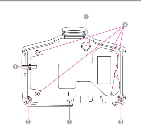
Base
|
Name |
Function |
A |
Security cable |
Pass a commercially available wire lock through here and |
|
installation point |
lock it in place. |
|
|
sp.55 |
|
|
|
Part Names and Functions |
9 |
|
|
|
Name |
Function |
B |
Rear feet |
When setup on a surface such as a desk, turn to extend and |
|
|
retract to adjust the horizontal tilt. |
|
|
sp.22 |
|
|
|
C |
Screw holes to fix the |
Screw holes to fix the cable cover in place. |
|
cable cover |
sp.37 |
|
|
|
D |
Ceiling mount fixing |
Attach the optional Ceiling Mount here when suspending |
|
points (four points) |
the projector from a ceiling. |
|
|
sp.17 |
|
|
|
E |
Front adjustable foot |
When setup on a surface such as a desk, extend the foot to |
|
|
adjust the position of the image. |
|
|
sp.21 |
|
|
|
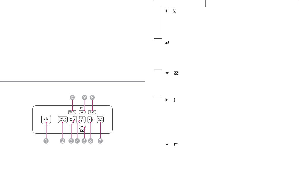
Control Panel
|
Name |
Function |
A |
[t] button |
Turns the projector power on or off. |
|
|
|
B |
[Source Search] |
Changes to the next input source that is sending an image. |
|
button |
|
|
|
|
Name |
Function |
C [ ]/[ ] buttons |
• Displays the Control Panel Lock screen allowing you to |
|
make settings to lock the control panel buttons. |
s p.53
•If pressed when the Configuration menu or the Help screen is displayed, this button selects menu items and setting values.
D [ ] button |
• When the Configuration menu or the Help screen is |
|
displayed, it accepts and enters the current selection and |
|
moves to the next level. |
•If pressed while projecting analog RGB signals from the Computer port or the BNC port, you can automatically optimize Tracking, Sync., and Position.
E [ ]/[ ] buttons |
• Displays a test pattern. |
s p.22
•If pressed when the Configuration menu or the Help screen is displayed, this button selects menu items and setting values.
F [ |
] /[ |
] buttons |
• Displays the Info menu from the Configuration menu. |
|
|
|
• If pressed when the Configuration menu or the Help |
|
|
|
screen is displayed, this button selects menu items and |
|
|
|
setting values. |
|
|
||
G [A/V Mute] button |
Turns the video and audio on or off. |
||
|
|
||
H [Esc] button |
• Stops the current function. |
||
|
|
|
• If pressed when the Configuration menu is displayed, it |
|
|
|
moves to the previous menu level. |
|
|
|
|
I [ |
]/[ |
] buttons |
• Performs screen adjustments using the settings in |
|
|
|
Geometric Correction from the Configuration menu. |
|
|
|
s p.39 |
|
|
|
• If pressed when the Configuration menu or the Help |
|
|
|
screen is displayed, this button selects menu items and |
|
|
|
setting values. |
|
|
||
J [Menu] button |
Displays and closes the Configuration menu. |
||

Part Names and Functions |
10 |
|
|
Remote Control
See the User's Guide for information on basic remote control operations.
Remote control operating range
a• To restrict reception of the operation signals from the remote control, set Remote Receiver.
Press [Menu] button > Settings > Remote Receiver
•When using a remote control provided with other Epson projectors, set the Remote Control Type.
Press [Menu] button > Extended > Operation > Remote Control
Type
The operating range depends on the remote control that you use.
Part Names and Functions |
11 |
|
|
You can perform the following operations by simply pressing one button on the remote control.
Operation |
Settings |
Reverses the top and bottom of a projected |
Hold down the [A/V Mute] button for at |
image. (Changes Front and Front/Ceiling |
least five seconds. |
in Projection) |
|
Sets password protection sp.51 |
Hold down the [Freeze] button for at least |
|
five seconds. Make the settings on the |
|
Password Protection screen. |
Applies or releases a partial lock for the |
Hold down the [Help] button for at least |
remote control buttons. sp.54 |
five seconds. |
|
|
Resets the Remote Receiver settings on |
Hold down the [Menu] button for at least |
the Configuration menu. (Enables all of |
15 seconds. |
the projector's remote receivers.) |
|
|
|
Displays frequently used Configuration |
Press the [User1], [User2], or [User3] |
menu items instantly. |
button. You can set the menu item |
|
assigned to each button from User |
|
Button. |
|
Press [Menu] button > Settings > User |
|
Button |
|
The following items can be assigned. |
|
Power Consumption, Info, Progressive, |
|
Geometric Correction, Multi- |
|
Projection, Resolution, Memory, or |
|
Image Processing |
Turning On and Off |
12 |
|
|
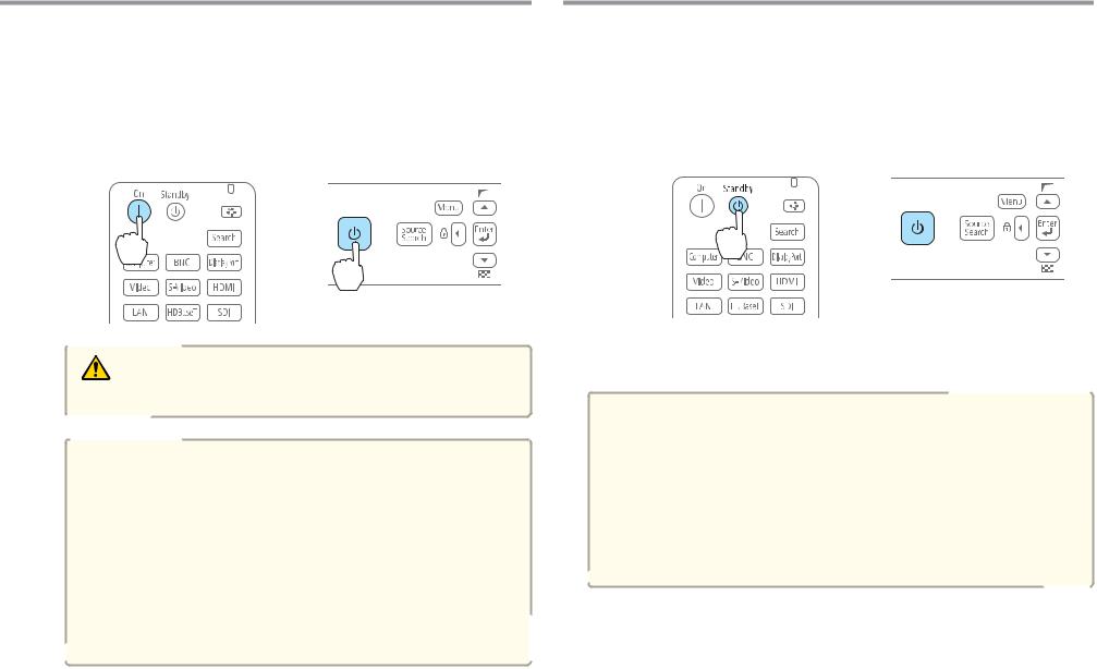
Turning On |
Turning Off |
a |
Connect the power cable. |
|
|
|
|
b |
Connect the power cable supplied. |
|
Turning on the projector. |
|
|
|
|
|
|
Using the remote control |
Using the control panel |
a b
Turn off any connected devices.
Press [t] once on the remote control, or press [t] twice on the control panel.
Using the remote control |
Using the control panel |
 × 2
× 2
Warning
Do not look into the lens during projection.
a• We recommend setting the focus, zoom, and lens shift at least 30 minutes after you start the projection, because images are not stable right after turning on the projector.
•When using at an altitude of 1500 m or more, make sure you set High Altitude Mode to On.
Press [Menu] button > Extended > Operation > High
Altitude Mode
•When you turn on the projector for the first time, the message "Do you want to set the time?" is displayed. See the following for more information on setting the time.
s p.25
c When the projector beeps twice, disconnect the power cable.
aTo prevent accidental operations, set Standby Confirmation to On to display a confirmation message asking if you want to turn off the projector when the [t] button is pressed on the remote control.
(When Remote Control Type is set to Simple, you cannot make
Standby Confirmation settings.)
Press [Menu] button > Extended > Display > Standby Confirmation
After making the settings, a confirmation message is displayed when you press the [t] button on the remote control, and the projector turns off if you press the [t] button one more time.
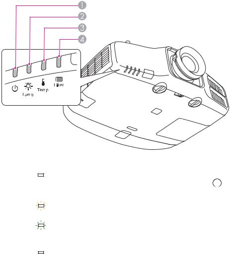
Reading the Indicators |
13 |
|
|
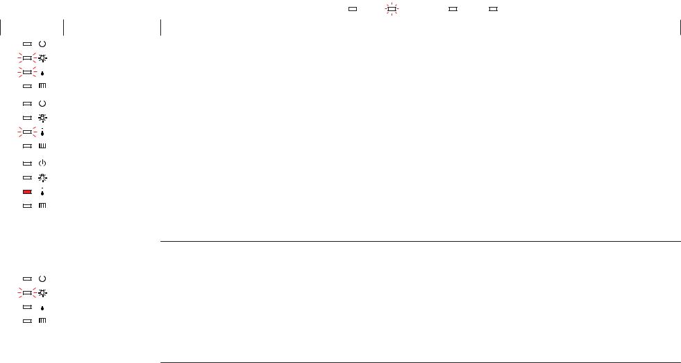
The projector is provided with the following four indicators that indicate the operating status of the projector.
A Power |
indicator |
Indicates the |
|
operating status. |
|
|
|
|
|
|
|
|
Standby condition |
|
] button on the remote control, or the [t] button |
|
|
|
|
|
|||
|
|
|
|
|
In this status, you can start projecting by pressing the [ |
|
|
|
|
|
|
|
|||
|
|
|
|
|
on the control panel. |
|
|
|
|
|
|
|
Preparing for network monitoring or cool down in progress |
||
|
|
|
|
|
|||
|
|
|
|
|
All buttons are disabled while the indicator is flashing. |
|
|
|
|
|
|
|
Warming up |
|
|
|
|
|
|
|
Warm-up time is about 30 seconds. After warm-up is complete, the indicator stops flashing. |
||
|
|
|
|
|
The [t] button is disabled during warm-up. |
|
|
|
|
|
|
|
Projecting |
|
|
|
|
|
|
|
|
|
|
B Lamp |
indicator |
Indicates the projection lamp status. |
|
|
|||
C Temp |
indicator |
Indicates the internal temperature status. |
|
|
|||
D Filter |
indicator |
Indicates the |
|
air filter status. |
|
|
|
Reading the Indicators |
14 |
|
|
Refer to the following table to see what the indicators mean and how to |
remedy problems that they indicate. |
|
||||||||||||
If all indicators are off, check that the power cord is connected correctly and that the power is being supplied normally. |
||||||||||||||
Sometimes, |
when the power cord |
is unplugged, the [t] indicator remains |
lit for a short |
period, but |
this is not |
a fault. |
||||||||
|
|
|
|
|
|
|
|
|
: Lit |
|
: Flashing |
: Off |
|
: Varies according to the projector status |
|
|
|
|
|
|
|
|
|
|
|
||||
|
|
|
|
|
|
|
|
|
|
|
||||
Status |
Cause |
|
|
|
Remedy or Status |
|
||||||||
|
|
|
|
|
Internal Error |
Stop using the projector, remove the power plug from the electrical outlet, and contact your local dealer or the nearest address provided in the |
||||||||
|
|
|
|
|
||||||||||
|
|
|
|
|
|
Epson Projector Contact List. |
|
|
|
|
|
|
|
|
|
|
|
|
|
|
|
|
|
|
|
|
|
|
|
|
|
|
|
|
|
s"Epson Projector Contact List" p.67 |
|
|
|
|
|
|
|
|
|
|
|
|
|
|
|
||||||||
|
|
|
|
|
|
|
||||||||
|
|
|
|
|
Fan Error |
Stop using the projector, remove the power plug from the electrical outlet, and contact your local dealer or the nearest address provided in the |
||||||||
|
|
|
|
|
||||||||||
|
|
|
|
|
Sensor Error |
Epson Projector Contact List. |
|
|
|
|
|
|
|
|
|
|
|
|
|
|
s"Epson Projector Contact List" p.67 |
|
|
|
|
|
|
|
|
|
|
|
|
|
|
|
||||||||
|
|
|
|
|
|
|
||||||||
|
|
|
|
|
High Temp Error |
The lamp turns off automatically and projection stops. Wait for about five minutes. After about five minutes the projector switches to standby |
||||||||
|
|
|
|
|
||||||||||
|
|
|
|
|
||||||||||
|
|
|
|
|
(Overheating) |
mode, so check the following two points. |
|
|
|
|
|
|
|
|
•Check that the air filter and air exhaust vent are clear, and that the projector is not positioned against a wall.
•If the air filter is clogged, remove the power plug from the electrical outlet, and clean or replace it.
If the error continues after checking the points above, stop using the projector, remove the power plug from the electrical outlet, and contact your local dealer or the nearest address provided in the Epson Projector Contact List.
s"Epson Projector Contact List" p.67
|
|
|
|
When using at an altitude of 1500 m or more, set High Altitude Mode to On. |
|
|
|
|
Press [Menu] button > Extended > Operation > High Altitude Mode |
|
|
|
|
|
|
|
|
Lamp Error |
Check the following two points after turning off the projector and removing the power plug from the electrical outlet. |
|
|
|
||
|
|
|
||
|
|
|
Lamp Failure |
• Take out the lamp and check if it is cracked. |
|
|
|||
|
|
|
|
• Clean the air filter. |
|
|
|
|
|
|
|
|
|
If the lamp is not cracked: Reinstall the lamp and connect the plug to an electrical outlet. |
|
|
|
|
If the error continues: Stop using the projector, remove the power plug from the electrical outlet, and contact your local dealer or the nearest |
|
|
|
|
address provided in the Epson Projector Contact List. |
|
|
|
|
s"Epson Projector Contact List" p.67 |

Reading the Indicators |
15 |
|
|
Status |
Cause |
Remedy or Status |
||||
|
|
|
|
|
|
If the lamp is cracked: Contact your local dealer or the nearest address provided in the Epson Projector Contact List. (Images cannot be |
|
|
|
|
|
|
projected until the lamp is replaced.) |
|
|
|
|
|
|
s"Epson Projector Contact List" p.67 |
|
|
|
|
|
|
|
|
|
|
|
|
|
When using at an altitude of 1500 m or more, set High Altitude Mode to On. |
|
|
|
|
|
|
Press [Menu] button > Extended > Operation > High Altitude Mode |
|
|
|
|
|
|
|
|
|
|
|
|
Auto Iris Error |
Stop using the projector, remove the power plug from the electrical outlet, and contact your local dealer or the nearest address provided in the |
|
|
|
|
|
||
|
|
|
|
|
Power Err. (Ballast) |
Epson Projector Contact List. |
|
|
|
|
|
||
|
|
|
|
|
|
s"Epson Projector Contact List" p.67 |
|
|
|
|
|
|
|
|
|
|
|
|
|
|
|
|
|
|
|
Filter Airflow Error |
Check the following two points. |
|
|
|
|
|
||
|
|
|
|
|
|
• Check that the air filter and air exhaust vent are clear, and that the projector is not positioned against a wall. |
|
|
|
|
|
|
• If the air filter is clogged, remove the power plug from the electrical outlet, and clean or replace it. |
|
|
|
|
|
|
After checking, connect the power plug to an electrical outlet. |
|
|
|
|
|
|
If the error continues after checking the points above, stop using the projector, remove the power plug from the electrical outlet, and contact |
|
|
|
|
|
|
|
|
|
|
|
|
|
your local dealer or the nearest address provided in the Epson Projector Contact List. |
|
|
|
|
|
|
s"Epson Projector Contact List" p.67 |
|
|
|
|
|
|
|
|
|
|
|
|
High Temp Warning |
This is not an abnormality. However, if the temperature rises too high again, projection stops automatically. Check the following two points. |
|
|
|
|
|
||
|
|
|
|
|
|
• Check that the air filter and air exhaust vent are clear, and that the projector is not positioned against a wall. |
|
|
|
|
|
|
• If the air filter is clogged, remove the power plug from the electrical outlet, and clean or replace it. |
|
|
|
|
|
|
|
|
|
|
|
|
|
|
|
|
|
|
|
Replace Lamp |
Replace with a new lamp after turning off the projector and removing the power plug from the electrical outlet. |
|
|
|
|
|
||
|
|
|
|
|
||
|
|
|
|
|
|
If you continue to use the lamp after the replacement period has passed, the possibility that the lamp may explode increases. Replace it with a |
|
|
|
|
|
|
|
|
|
|
|
|
|
new lamp as soon as possible. |
|
|
|
|
|
|
|
|
|
|
|
|
Low Air Flow |
Check the following two points after turning off the projector and removing the power plug from the electrical outlet. |
|
|
|
|
|
||
|
|
|
|
|
||
|
|
|
|
|
|
• Check that the air filter and air exhaust vent are clear, and that the projector is not positioned against a wall. |
|
|
|
|
|
|
• If the air filter is clogged, remove the power plug from the electrical outlet, and clean or replace it. |
|
|
|
|
|
|
If the error continues after checking the points above, stop using the projector, remove the power plug from the electrical outlet, and contact |
|
|
|
|
|
|
your local dealer or the nearest address provided in the Epson Projector Contact List. |
|
|
|
|
|
|
|
|
|
|
|
|
|
|
|
|
|
|
|
|
s"Epson Projector Contact List" p.67 |
|
|
|
|
|
|
|

Reading the Indicators |
16 |
|
|
Status |
Cause |
Remedy or Status |
||||
|
|
|
|
|
Air Filter Notice |
"Time to clean the air filter. Clean or replace the air filter."is displayed. Clean the air filter after turning off the projector and removing the power |
|
|
|
|
|
||
|
|
|
|
|
|
plug from the electrical outlet. |
|
|
|
|
|
|
The indicators or messages regarding Air Filter Notice are displayed only when Air Filter Notice is set to On from the Configuration menu. |
|
|
|
|
|
|
Press [Menu] button > Extended > Display > Air Filter Notice |
|
|
|
|
|
|
|
|
|
|
|
|
|
|
aIf the indicators are in a state not shown in this table, stop using the projector, remove the power plug from the electrical outlet, and contact your local dealer or the nearest address provided in the Epson Projector Contact List.
s "Epson Projector Contact List" p.67
Installing the Projector |
17 |
|
|
Installation Requirements
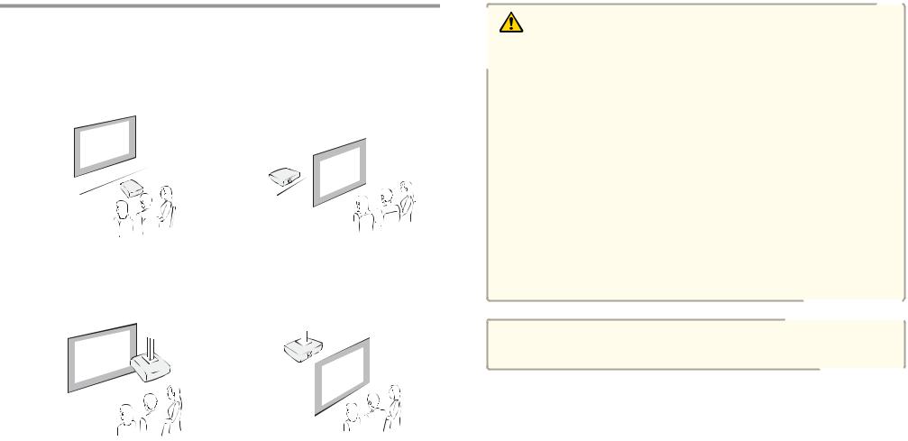
The projector supports the following four different projection methods. Install the projector according to the conditions of the installation location.
•Project images from in front of the screen. (Front projection)
•Project images from behind a translucent screen. (Rear projec tion)
•Suspend the projector from the ceiling and project images from in front of a screen. (Front/Ceil ing projection)
•Suspend the projector from the ceiling and project images from behind a translucent screen.
(Rear/Ceiling projection)
Warning
•A special method of installation is required when suspending the projector from a ceiling (ceiling mount). If installation work is not carried out correctly, the projector could fall down. This may result in injury or accidents.
Contact your dealer or the nearest address provided in the Epson Projector Contact List if you want to use this installation method. s "Epson Projector Contact List" p.67
•If you use adhesives on the Ceiling mount fixing points to prevent the screws from loosening, or if you use things such as lubricants or oils on the projector, the projector case may crack causing it to fall from its ceiling mount. This could cause serious injury to anyone under the ceiling mount and could damage the projector.
When installing or adjusting the ceiling mount, do not use adhesives to prevent the screws from loosening and do not use oils or lubricants and so on.
•Do not cover the projector's air intake vent or air exhaust vent. If either of the vents are covered, the internal temperature could rise and cause a fire.
Attention
Do not use the projector on its side. This may cause malfunctions to occur.
Installing the Projector |
18 |
|
|
a• An optional ceiling mount is required when suspending the projector from a ceiling.
•The default Projection setting is Front. You can change from Front to Rear from the Configuration menu.
Press [Menu] button > Extended > Projection
•You can change the Projection mode as follows by pressing down the [A/V Mute] button on the remote control for about five seconds.
FrontWFront/Ceiling RearWRear/Ceiling
•When mounted on a ceiling, set Inv Direction Button to On so that the operations and movement of the [ ], [
], [ ], [
], [  ], and [
  ] buttons on the control panel match.
Press [Menu] button > Extended > Operation > Inv Direction
Button
The projector can be installed at the following angles.
Vertical: Tilt up to ±30 degrees. If you use the projector tilted at an angle of more than 30 degrees it could be damaged and cause an accident.
30 |
30 |
30 |
30 |
Horizontal: Can be tilted within the range of expansion and contraction for the rear feet. s p.22
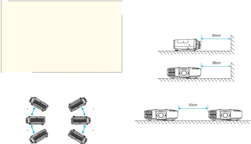
Make sure there is a gap of at least 50 cm between the wall and the air exhaust vent and the air intake vent.
Air exhaust vent
Air intake vent
When setting up multiple projectors, make sure there is a gap of at least 50 cm between the projectors. Also, make sure the heat coming out of the air exhaust is not taken in through the air inlet.
Installing the Projector
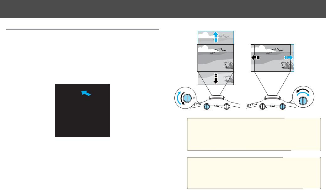
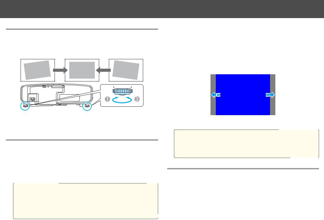
Adjusting the Position of the Projected Image
(Lens Shift)
The lens can be shifted to adjust the position of the projected image, for example, when the projector cannot be installed directly in front of the screen.
a Release the lens shift dial lock.
b Turn the vertical and horizontal lens shift dials on the projector to adjust the position of the projected image.
19
Attention
When adjusting the image height with the vertical lens shift dial, adjust by moving the image from the bottom to the top. If it is adjusted from the top to the bottom, the image position may move down slightly after adjusting.
a• We recommend setting the focus, zoom, and lens shift at least 30 minutes after you start the projection, because images are not stable right after turning on the projector.
•The image will be clearest when both the vertical and horizontal lens shift are set in the center.

Installing the Projector
The ranges within which the image can be moved are shown below.
EB-4955WU/EB-4950WU/EB-4855WU/EB-4850WU
ACenter of lens
BProjected image when lens shift is set in the center
20
EB-4750W/EB-4650/EB-4550
ACenter of lens
BProjected image when lens shift is set in the center
CMaximum range EB-4750W: V x 70% EB-4650/EB-4550: V x 58%
DWhen horizontal lens shift is set to the maximum EB-4750W: V x 60%
EB-4650/EB-4550: V x 50%
The position of the projected image cannot be moved to both the horizontal and vertical maximum values.
Installing the Projector |
21 |
|
|
When you have finished making adjustments, lock the lens shift |
Adjusting the Focus |
c dial lock. |
Adjust the focus ring.
Adjusting the Zoom
Turn the zoom ring to adjust the zoom.
 W T
W T 
Adjusting the Image Position (When Setup on a Desk)
Extend or retract the front foot to make adjustments. You can adjust the position of the image by tilting the projector up to 10 degrees.
AExtend the front foot.
BRetract the front foot.
aThe larger the angle of tilt, the harder it becomes to focus. Install the projector so that it only needs to be tilted at a small angle.
Installing the Projector |
22 |
Adjusting the Horizontal Tilt (When Setup on a Desk)
Extend and retract the rear feet to adjust the projector's horizontal tilt.
AExtend the rear foot.
BRetract the rear foot.
Screen Settings
Set the Screen Type to 4:3, 16:9, or 16:10 according to the aspect ratio of the screen being used
Press [Menu] button > Extended > Display > Screen > Screen Type
The area where the image is displayed matches the shape of the screen.
aThe default values are shown below. EB-4955WU/EB-4950WU/EB-4855WU/EB-4850WU/EB-4750W: 16:10
EB-4650/EB-4550: 4:3
You do not need to set the Screen Type when the default value is the same as the aspect ratio for the screen being used.
Adjusting the position of the image on the projected screen
You can adjust the position of the image if there are margins between the edge of the image and the projected screen frame due to the Screen Type setting.
Press [Menu] button > Extended > Display > Screen > Screen Position
Example: When the Screen Type is set to 4:3 for EB-4950WU
You can move the image to the left and right.
aThe Screen Position cannot be adjusted in the following situations.
•If the Screen Type is set to 16:10 when using EB-4955WU/ EB-4950WU/EB-4855WU/EB-4850WU/EB-4750W
•If the Screen Type is set to 4:3 when using EB-4650/EB-4550
Displaying a Test Pattern
A test pattern can be displayed to adjust the projection status without connecting video equipment.
The shape of a test pattern is according to the setting of Screen Type. Set
Screen Type first.
Press [Menu] button > Extended > Display > Screen > Screen Type
Installing the Projector
a Press the [Test Pattern] button on the remote control or the [ ] button on the control panel while projecting.
b |
Press the [ ][ ] buttons on the remote control or the [ ] button |
||||||||||||||
|
on the control panel to change the test pattern. |
||||||||||||||
|
Using the remote control |
|
|
Using the control panel |
|||||||||||
|
|
|
|
|
|
|
|
|
|
|
|
|
|
|
|
|
|
|
|
|
|
|
|
|
|
|
|
|
|
|
|
|
|
|
|
|
|
|
|
|
|
|
|
|
|
|
|
|
|
|
|
|
|
|
|
|
|
|
|
|
|
|
|
|
|
|
|
|
|
|
|
|
|
|
|
|
|
|
|
|
|
|
|
|
|
|
|
|
|
|
|
|
|
|
|
|
|
|
|
|
|
|
|
|
|
|
|
|
|
|
|
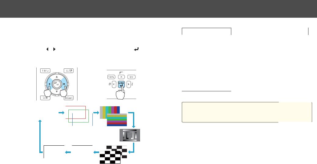
The following image adjustments can be made while the test pattern is being displayed.
Top Menu Name |
Sub Menu/Items |
Image |
Color Mode |
|
|
|
Abs. Color Temp. |
|
|
23
Top Menu Name |
Sub Menu/Items |
|
Advanced |
|
- Gamma* |
|
- RGB |
|
- RGBCMY |
|
|
|
Reset |
|
|
Signal |
Auto Setup |
|
|
Settings |
Geometric Correction s p.39 |
|
|
Extended |
Multi-Projection |
-Multi-screen s p.46
* Except for custom settings of gamma
aTo set menu items that cannot be set while the test pattern is being displayed or to fine-tune the projected image, project an image from the connected device.

Setting Up |
24 |
ID Settings
When an ID is set for the projector and the remote control, you can use the remote control to operate only the projector with a matching ID. This is very useful when managing multiple projectors.
a• Operation using the remote control is possible only for projectors that are within the operating range of the remote control.
s p.10
•When Remote Control Type is set to Simple from Operation in the
configuration menu, you cannot set the remote control ID.
•IDs are ignored when the projector ID is set to Off or the remote control ID is set to 0.
Set the projector ID
Press [Menu] button > Extended > Multi-Projection > Projector ID
Select the ID you want to set, and then press the [ ] button.
Checking the Projector ID
During projection, press the [Help] button while holding the [ID] button.
Remote control
When you press the buttons, the current Projector ID is displayed on the projection screen. It disappears in about three seconds.
Setting the remote control ID
a Set the remote control [ID] switch to On.
Loading...