


User’s Guide

Notations Used in This Guide
•Safety indications
The documentation and the projector use graphical symbols to show how to use the projector safely. Please understand and respect these caution symbols in order to avoid injury to persons or property.
|
|
Warning |
This symbol indicates information that, if ignored, could possibly result in personal injury or even death due to incorrect handling. |
|
|
|
|
|
|
|
|
Caution |
This symbol indicates information that, if ignored, could possibly result in personal injury or physical damage due to incorrect handling. |
|
|
|
|
|
|
• General information indications |
|
|||
|
|
|
|
|
|
|
Attention |
Indicates procedures which may result in damage or injury if sufficient care is not taken. |
|
|
|
|
|
|
|
|
q |
Indicates additional information and points which may be useful to know regarding a topic. |
|
|
|
|
|
|
|
|
|
|
|
|
|
s |
Indicates a page where detailed information regarding a topic can be found. |
|
|
|
|
|
|
|
|
g |
Indicates that an explanation of the underlined word or words in front of this symbol appears in the glossary of terms. See the "Glossary" |
|
|
|
|
|
section of the "Appendix". s p.159 |
|
|
|
|
|
|
|
|
|
Indicates operating methods and the order of operations. |
|
|
Procedure |
|
|
|
|
|
|
The procedure indicated should be carried out in the order of the numbered steps. |
|
|
[(Name)] |
Indicates the name of the buttons on the Remote Control or the Control panel. |
|
|
|
|
|
Example: [Esc] button |
|
|
|
||
|
"(Menu Name)" |
Indicates the configuration menu items. |
||
|
Brightness (Boldface) |
Example: |
||
|
|
|
|
Select "Brightness" from the Image menu. |
|
|
|
|
Image menu - Brightness |
|
|
|
|
|

Contents |
|
3 |
|
|
|
Notations Used in This Guide . . . . . . . . . . . . . . . . . . . . . . . . 2
Introduction
Projector Features . . . . . . . . . . . . . . . . . . . . . . . . . . . . . . . . . . . . . . . . . . 8
Ease of Use when Installed on a Ceiling Mount . . . . . . . . . . . . . . . . . . . . . . . . . . 8 Reliability You can Depend on . . . . . . . . . . . . . . . . . . . . . . . . . . . . . . . . . . . . . . 8 Meets a Wide Range of Needs . . . . . . . . . . . . . . . . . . . . . . . . . . . . . . . . . . . . . . 8 Enhanced Security Functions . . . . . . . . . . . . . . . . . . . . . . . . . . . . . . . . . . . . . . 8 Easy to Handle . . . . . . . . . . . . . . . . . . . . . . . . . . . . . . . . . . . . . . . . . . . . . . . . 9 Monitoring and Control Functions . . . . . . . . . . . . . . . . . . . . . . . . . . . . . . . . . . . 9 Taking Full Advantage of a Network Connection (EB-G5950/G5650W only) . . . . . . . 9
Part Names and Functions . . . . . . . . . . . . . . . . . . . . . . . . . . . . . . . . . . 10
Front/Top . . . . . . . . . . . . . . . . . . . . . . . . . . . . . . . . . . . . . . . . . . . . . . . . . . . 10
Base . . . . . . . . . . . . . . . . . . . . . . . . . . . . . . . . . . . . . . . . . . . . . . . . . . . . . . 11
Rear . . . . . . . . . . . . . . . . . . . . . . . . . . . . . . . . . . . . . . . . . . . . . . . . . . . . . . . 12
Interface . . . . . . . . . . . . . . . . . . . . . . . . . . . . . . . . . . . . . . . . . . . . . . . . . . . 12
EB-G5950/G5650W . . . . . . . . . . . . . . . . . . . . . . . . . . . . . . . . . . . . . . . . . . 12
EB-G5900/G5600 . . . . . . . . . . . . . . . . . . . . . . . . . . . . . . . . . . . . . . . . . . . . 13
EB-G5800/G5500 . . . . . . . . . . . . . . . . . . . . . . . . . . . . . . . . . . . . . . . . . . . . 14
Control Panel . . . . . . . . . . . . . . . . . . . . . . . . . . . . . . . . . . . . . . . . . . . . . . . . 15
Remote Control . . . . . . . . . . . . . . . . . . . . . . . . . . . . . . . . . . . . . . . . . . . . . . . 16
Installing the batteries . . . . . . . . . . . . . . . . . . . . . . . . . . . . . . . . . . . . . . . . 18
Operating range of remote control . . . . . . . . . . . . . . . . . . . . . . . . . . . . . . . . 19
Useful Functions
Adjusting the Projected Image . . . . . . . . . . . . . . . . . . . . . . . . . . . . . . 21
Displaying a Test Pattern . . . . . . . . . . . . . . . . . . . . . . . . . . . . . . . . . . . . . . . . 21 Adjusting the Position of the Projected Image (Lens Shift) . . . . . . . . . . . . . . . . . . 22 Correcting Distortion in the Projected Image . . . . . . . . . . . . . . . . . . . . . . . . . . . 22 Quick Corner . . . . . . . . . . . . . . . . . . . . . . . . . . . . . . . . . . . . . . . . . . . . . . . 23 H/V-Keystone . . . . . . . . . . . . . . . . . . . . . . . . . . . . . . . . . . . . . . . . . . . . . . 25
Changing the Projected Image . . . . . . . . . . . . . . . . . . . . . . . . . . . . . . 27
Automatically Detect Input Signal and Change the Projected Image (Source Search)
. . . . . . . . . . . . . . . . . . . . . . . . . . . . . . . . . . . . . . . . . . . . . . . . . . . . . . . . . . 27 Switch to the Target Image by Remote Control . . . . . . . . . . . . . . . . . . . . . . . . . 28
Changing the Aspect Ratio of the Projected Image . . . . . . . . . . . . 29
Changing the Aspect Mode (EB-G5950/G5900/G5800/G5600/G5500) . . . . . . . . . . |
30 |
Projecting images from video equipment . . . . . . . . . . . . . . . . . . . . . . . . . . . |
30 |
Projecting images from the HDMI input port (EB-G5950/G5900/G5600 only) |
|
. . . . . . . . . . . . . . . . . . . . . . . . . . . . . . . . . . . . . . . . . . . . . . . . . . . . . . . . |
30 |
Projecting images from a computer . . . . . . . . . . . . . . . . . . . . . . . . . . . . . . . |
30 |
Changing the Aspect Mode (EB-G5650W) . . . . . . . . . . . . . . . . . . . . . . . . . . . . . |
31 |
Projecting images from video equipment or from the HDMI input port . . . . . . . |
31 |
Projecting images from a computer . . . . . . . . . . . . . . . . . . . . . . . . . . . . . . . |
31 |
Selecting the Projection Quality (Selecting Color Mode) . . . . . . . 33
Projecting Two Images Simultaneously (Split Screen) (EBG5950/G5900/G5650W/G5600 only) . . . . . . . . . . . . . . . . . . . . . . . . . 34
Input Sources for Split Screen Projection . . . . . . . . . . . . . . . . . . . . . . . . . . . . . . 34 Operating Procedures . . . . . . . . . . . . . . . . . . . . . . . . . . . . . . . . . . . . . . . . . . 34 Projecting on a split screen . . . . . . . . . . . . . . . . . . . . . . . . . . . . . . . . . . . . . 34 Switching the left and right screens . . . . . . . . . . . . . . . . . . . . . . . . . . . . . . . 35 Switching the left and right image sizes . . . . . . . . . . . . . . . . . . . . . . . . . . . . 35 Ending the split screen . . . . . . . . . . . . . . . . . . . . . . . . . . . . . . . . . . . . . . . . 36 Restrictions during Split Screen Projection . . . . . . . . . . . . . . . . . . . . . . . . . . . . 36 Operating restrictions . . . . . . . . . . . . . . . . . . . . . . . . . . . . . . . . . . . . . . . . 36 Restriction relating to images . . . . . . . . . . . . . . . . . . . . . . . . . . . . . . . . . . . 37
Functions for Enhancing Projection . . . . . . . . . . . . . . . . . . . . . . . . . 38
Hiding the Image and Sound Temporarily (A/V Mute) . . . . . . . . . . . . . . . . . . . . . 38 Freezing the Image (Freeze) . . . . . . . . . . . . . . . . . . . . . . . . . . . . . . . . . . . . . . 38 Pointer Function (Pointer) . . . . . . . . . . . . . . . . . . . . . . . . . . . . . . . . . . . . . . . . 39 Enlarging Part of the Image (E-Zoom) . . . . . . . . . . . . . . . . . . . . . . . . . . . . . . . . 40
Limitation of the Number of the Target Projectors when Using Multiple Projectors . . . . . . . . . . . . . . . . . . . . . . . . . . . . . . . . . . . . . . . . 42
Setting the Projector ID . . . . . . . . . . . . . . . . . . . . . . . . . . . . . . . . . . . . . . . . . 42 Checking the Projector ID . . . . . . . . . . . . . . . . . . . . . . . . . . . . . . . . . . . . . . . . 42

Contents |
|
4 |
|
|
|
Setting the Remote Control ID . . . . . . . . . . . . . . . . . . . . . . . . . . . . . . . . . . . . . 43
Color Correction when Projecting from Multiple Projectors (Multi-screen Color Adjustment) . . . . . . . . . . . . . . . . . . . . . . . . . . . . 45
Summary of Correction Procedure . . . . . . . . . . . . . . . . . . . . . . . . . . . . . . . . . . 45
Correction Method . . . . . . . . . . . . . . . . . . . . . . . . . . . . . . . . . . . . . . . . . . . . 45
Saving a User's Logo . . . . . . . . . . . . . . . . . . . . . . . . . . . . . . . . . . . . . . . 47
Security Functions . . . . . . . . . . . . . . . . . . . . . . . . . . . . . . . . . . . . . . . . . 49
Managing Users (Password Protect) . . . . . . . . . . . . . . . . . . . . . . . . . . . . . . . . . 49 Type of Password Protect . . . . . . . . . . . . . . . . . . . . . . . . . . . . . . . . . . . . . . 49 Setting Password Protect . . . . . . . . . . . . . . . . . . . . . . . . . . . . . . . . . . . . . . 49 Entering the Password . . . . . . . . . . . . . . . . . . . . . . . . . . . . . . . . . . . . . . . . 50 Restricting Operation (Control Panel Lock) . . . . . . . . . . . . . . . . . . . . . . . . . . . . 51 Anti-Theft Lock . . . . . . . . . . . . . . . . . . . . . . . . . . . . . . . . . . . . . . . . . . . . . . . 52 Installing the wire lock . . . . . . . . . . . . . . . . . . . . . . . . . . . . . . . . . . . . . . . . 52 Anti-theft projection lens . . . . . . . . . . . . . . . . . . . . . . . . . . . . . . . . . . . . . . 52
Configuration Menu
Using the Configuration Menu . . . . . . . . . . . . . . . . . . . . . . . . . . . . . . 54
Image Menu . . . . . . . . . . . . . . . . . . . . . . . . . . . . . . . . . . . . . . . . . . . . . . . 55
Signal Menu . . . . . . . . . . . . . . . . . . . . . . . . . . . . . . . . . . . . . . . . . . . . . . . 57
Settings Menu . . . . . . . . . . . . . . . . . . . . . . . . . . . . . . . . . . . . . . . . . . . . . 59
Extended Menu . . . . . . . . . . . . . . . . . . . . . . . . . . . . . . . . . . . . . . . . . . . . 61
Network Menu (EB-G5900/G5800/G5600/G5500) . . . . . . . . . . . . . 64
Network Menu (EB-G5950/G5650W) . . . . . . . . . . . . . . . . . . . . . . . . . 67
Notes on Operating the Network Menu . . . . . . . . . . . . . . . . . . . . . . . . . . . . . . 68 Soft Keyboard Operations . . . . . . . . . . . . . . . . . . . . . . . . . . . . . . . . . . . . . . . . 68 Basic Menu . . . . . . . . . . . . . . . . . . . . . . . . . . . . . . . . . . . . . . . . . . . . . . . . . . 69 Wireless LAN Menu . . . . . . . . . . . . . . . . . . . . . . . . . . . . . . . . . . . . . . . . . . . . 70 Security Menu (Only available when the Wireless LAN unit is installed) . . . . . . . . . 72
When WEP is selected . . . . . . . . . . . . . . . . . . . . . . . . . . . . . . . . . . . . . . . . 73 When WPA-PSK(TKIP/AES) or WPA2-PSK(TKIP/AES) is selected . . . . . . . . . . . . . 75 When EAP-TLS is selected . . . . . . . . . . . . . . . . . . . . . . . . . . . . . . . . . . . . . . 76
EAP-TTLS/MD5, EAP-TTLS/MS-CHAPv2, PEAP/MS-CHAPv2, PEAP/GTC, LEAP, EAP- Fast/MS-CHAPv2, EAP-Fast/GTC is selected . . . . . . . . . . . . . . . . . . . . . . . . . . 77
Wired LAN Menu . . . . . . . . . . . . . . . . . . . . . . . . . . . . . . . . . . . . . . . . . . . . . . 78 Mail Menu . . . . . . . . . . . . . . . . . . . . . . . . . . . . . . . . . . . . . . . . . . . . . . . . . . 79 Others Menu . . . . . . . . . . . . . . . . . . . . . . . . . . . . . . . . . . . . . . . . . . . . . . . . . 80 Reset Menu . . . . . . . . . . . . . . . . . . . . . . . . . . . . . . . . . . . . . . . . . . . . . . . . . 81
Info Menu (Display Only) . . . . . . . . . . . . . . . . . . . . . . . . . . . . . . . . . . . 82
Reset Menu . . . . . . . . . . . . . . . . . . . . . . . . . . . . . . . . . . . . . . . . . . . . . . . 83
Troubleshooting
Using the Help . . . . . . . . . . . . . . . . . . . . . . . . . . . . . . . . . . . . . . . . . . . . . 85
Problem Solving . . . . . . . . . . . . . . . . . . . . . . . . . . . . . . . . . . . . . . . . . . . 87
Reading the Indicators . . . . . . . . . . . . . . . . . . . . . . . . . . . . . . . . . . . . . . . . . . 87 t Indicator is lit or flashing red . . . . . . . . . . . . . . . . . . . . . . . . . . . . . . . . . . 88 m oIndicator is flashing or lit . . . . . . . . . . . . . . . . . . . . . . . . . . . . . . . . . . . 89 When the Indicators Provide No Help . . . . . . . . . . . . . . . . . . . . . . . . . . . . . . . . 91 Problems relating to images . . . . . . . . . . . . . . . . . . . . . . . . . . . . . . . . . . . . 92 Problems when projection starts . . . . . . . . . . . . . . . . . . . . . . . . . . . . . . . . . 96 Other problems . . . . . . . . . . . . . . . . . . . . . . . . . . . . . . . . . . . . . . . . . . . . . 97 Interpreting Event IDs (EB-G5950/G5650W only) . . . . . . . . . . . . . . . . . . . . . . 99
Maintenance
Cleaning . . . . . . . . . . . . . . . . . . . . . . . . . . . . . . . . . . . . . . . . . . . . . . . . . 101
Cleaning the Projector's Surface . . . . . . . . . . . . . . . . . . . . . . . . . . . . . . . . . . . 101 Cleaning the Lens . . . . . . . . . . . . . . . . . . . . . . . . . . . . . . . . . . . . . . . . . . . . 101 Cleaning the Air Filter . . . . . . . . . . . . . . . . . . . . . . . . . . . . . . . . . . . . . . . . . . 101
Replacing Consumables . . . . . . . . . . . . . . . . . . . . . . . . . . . . . . . . . . . 104
Replacing the Lamp . . . . . . . . . . . . . . . . . . . . . . . . . . . . . . . . . . . . . . . . . . . 104

Contents |
|
5 |
|
|
|
Lamp replacement period . . . . . . . . . . . . . . . . . . . . . . . . . . . . . . . . . . . . . 104 How to replace the lamp . . . . . . . . . . . . . . . . . . . . . . . . . . . . . . . . . . . . . . 104 Resetting the Lamp Hours . . . . . . . . . . . . . . . . . . . . . . . . . . . . . . . . . . . . . 107 Replacing the Air Filter . . . . . . . . . . . . . . . . . . . . . . . . . . . . . . . . . . . . . . . . . 107 Air filter replacement period . . . . . . . . . . . . . . . . . . . . . . . . . . . . . . . . . . . 107 How to replace the air filter . . . . . . . . . . . . . . . . . . . . . . . . . . . . . . . . . . . . 107
Notes on Transportation . . . . . . . . . . . . . . . . . . . . . . . . . . . . . . . . . . 109
Moving Nearby . . . . . . . . . . . . . . . . . . . . . . . . . . . . . . . . . . . . . . . . . . . . . . 109
When Transporting . . . . . . . . . . . . . . . . . . . . . . . . . . . . . . . . . . . . . . . . . . . 109
Preparing packaging . . . . . . . . . . . . . . . . . . . . . . . . . . . . . . . . . . . . . . . . 109
Notes when packing and transporting . . . . . . . . . . . . . . . . . . . . . . . . . . . . 109
Monitoring and Controls
EasyMP Monitor . . . . . . . . . . . . . . . . . . . . . . . . . . . . . . . . . . . . . . . . . . 111
Changing Settings Using a Web Browser (Web Control) . . . . . . 112
Displaying Web Control . . . . . . . . . . . . . . . . . . . . . . . . . . . . . . . . . . . . . . . . 112
Displaying Web Remote . . . . . . . . . . . . . . . . . . . . . . . . . . . . . . . . . . . . . . . . 112
Using the Mail Notification Function to Report Problems . . . . . 114
Reading Problem Mail Notification Function . . . . . . . . . . . . . . . . . . . . . . . . . . 114
Management Using SNMP . . . . . . . . . . . . . . . . . . . . . . . . . . . . . . . . . 115
ESC/VP21 Commands . . . . . . . . . . . . . . . . . . . . . . . . . . . . . . . . . . . . . 116
Serial Connection . . . . . . . . . . . . . . . . . . . . . . . . . . . . . . . . . . . . . . . . . . . . 116 Communications protocol . . . . . . . . . . . . . . . . . . . . . . . . . . . . . . . . . . . . . . . 116 Command List . . . . . . . . . . . . . . . . . . . . . . . . . . . . . . . . . . . . . . . . . . . . . . . 116
About PJLink . . . . . . . . . . . . . . . . . . . . . . . . . . . . . . . . . . . . . . . . . . . . . 118 About Crestron RoomView® (EB-G5950/G5650W only) . . . . . . . 119
Operating a Projector from a Computer Window . . . . . . . . . . . . . . . . . . . . . . . 119 Displaying the operation window . . . . . . . . . . . . . . . . . . . . . . . . . . . . . . . 119 Using the operation window . . . . . . . . . . . . . . . . . . . . . . . . . . . . . . . . . . . 120 Using the tools window . . . . . . . . . . . . . . . . . . . . . . . . . . . . . . . . . . . . . . 121
Network Functions (EB-G5950/G5650W Only)
Projecting with "Connect to a Network Projector" (EB-G5950/ G5650W Only) . . . . . . . . . . . . . . . . . . . . . . . . . . . . . . . . . . . . . . . . . . . . 124
Making a WPS (Wi-Fi Protected Setup) Connection with a
Wireless LAN Access Point (EB-G5950/G5650W only) . . . . . . . . 125
Connection Setup Method . . . . . . . . . . . . . . . . . . . . . . . . . . . . . . . . . . . . . . 125 Making a connection using the push button method . . . . . . . . . . . . . . . . . . 126 Making a connection using the PIN Code Method . . . . . . . . . . . . . . . . . . . . . 127
Installation and Connections
Installation Methods . . . . . . . . . . . . . . . . . . . . . . . . . . . . . . . . . . . . . . 131
Switching the Projection Mode . . . . . . . . . . . . . . . . . . . . . . . . . . . . . . . . . . . 131
Connecting to Video Equipment . . . . . . . . . . . . . . . . . . . . . . . . . . . 133
Connecting to a Computer . . . . . . . . . . . . . . . . . . . . . . . . . . . . . . . . . . . . . . 133 Changing the video output from a laptop computer. . . . . . . . . . . . . . . . . . . 135 Connecting to Video Equipment . . . . . . . . . . . . . . . . . . . . . . . . . . . . . . . . . . 135
Connecting to External Equipment . . . . . . . . . . . . . . . . . . . . . . . . . 139
Connecting a LAN Cable . . . . . . . . . . . . . . . . . . . . . . . . . . . . . . . . . . . . . . . . 139 Connecting to an external monitor (EB-G5950/G5900/G5650W/G5600 only) . . . . 139 Connecting to External Speakers (EB-G5950/G5900/G5650W/G5600 only) . . . . . . 139
Installing Optional and Supplied Accessories . . . . . . . . . . . . . . . 141
Removing and Attaching the Projector Lens Unit . . . . . . . . . . . . . . . . . . . . . . . 141 Removing . . . . . . . . . . . . . . . . . . . . . . . . . . . . . . . . . . . . . . . . . . . . . . . . 141 Attaching . . . . . . . . . . . . . . . . . . . . . . . . . . . . . . . . . . . . . . . . . . . . . . . . 142 Installing the Wireless LAN Unit (ELPAP03) (EB-G5950/G5650W only) . . . . . . . . . . 143 Attaching . . . . . . . . . . . . . . . . . . . . . . . . . . . . . . . . . . . . . . . . . . . . . . . . 143 Reading the wireless LAN indicators . . . . . . . . . . . . . . . . . . . . . . . . . . . . . . 143 Attaching and Removing the Cable Cover . . . . . . . . . . . . . . . . . . . . . . . . . . . . 144 Attaching . . . . . . . . . . . . . . . . . . . . . . . . . . . . . . . . . . . . . . . . . . . . . . . . 144 Removing . . . . . . . . . . . . . . . . . . . . . . . . . . . . . . . . . . . . . . . . . . . . . . . . 145

Contents |
|
6 |
|
|
|
Appendix
Optional Accessories and Consumables . . . . . . . . . . . . . . . . . . . . 147
Optional accessories . . . . . . . . . . . . . . . . . . . . . . . . . . . . . . . . . . . . . . . . . . 147 Consumables . . . . . . . . . . . . . . . . . . . . . . . . . . . . . . . . . . . . . . . . . . . . . . . 148
Screen Size and Projection Distance . . . . . . . . . . . . . . . . . . . . . . . . 149
Projection Distance of EB-G5950/G5900/G5800/G5600/G5500 . . . . . . . . . . . . . . 149 Projection Distance of EB-G5650W . . . . . . . . . . . . . . . . . . . . . . . . . . . . . . . . . 150
Supported Monitor Displays . . . . . . . . . . . . . . . . . . . . . . . . . . . . . . . 151
Supported Monitor Displays for EB-G5950/G5900/G5800/G5600/G5500 . . . . . . . |
151 |
Computer signals (analog RGB) . . . . . . . . . . . . . . . . . . . . . . . . . . . . . . . . . |
151 |
Component Video . . . . . . . . . . . . . . . . . . . . . . . . . . . . . . . . . . . . . . . . . . |
151 |
Composite Video/S-Video . . . . . . . . . . . . . . . . . . . . . . . . . . . . . . . . . . . . . |
151 |
Input signals from HDMI input port (EB-G5950/G5900/G5600 only) . . . . . . . . . |
151 |
Supported Monitor Displays for EB-G5650W . . . . . . . . . . . . . . . . . . . . . . . . . . |
152 |
Computer signals (analog RGB) . . . . . . . . . . . . . . . . . . . . . . . . . . . . . . . . . |
152 |
Component Video . . . . . . . . . . . . . . . . . . . . . . . . . . . . . . . . . . . . . . . . . . |
152 |
Composite Video/S-Video . . . . . . . . . . . . . . . . . . . . . . . . . . . . . . . . . . . . . |
152 |
Input signals from HDMI input port . . . . . . . . . . . . . . . . . . . . . . . . . . . . . . |
153 |
Specifications . . . . . . . . . . . . . . . . . . . . . . . . . . . . . . . . . . . . . . . . . . . . 154
Projector General Specifications . . . . . . . . . . . . . . . . . . . . . . . . . . . . . . . . . . . |
154 |
Appearance . . . . . . . . . . . . . . . . . . . . . . . . . . . . . . . . . . . . . . . . . . . . . . 158
Glossary . . . . . . . . . . . . . . . . . . . . . . . . . . . . . . . . . . . . . . . . . . . . . . . . . 159
General Notes . . . . . . . . . . . . . . . . . . . . . . . . . . . . . . . . . . . . . . . . . . . . 161
About Notations . . . . . . . . . . . . . . . . . . . . . . . . . . . . . . . . . . . . . . . . . . . . . 161
General Notice . . . . . . . . . . . . . . . . . . . . . . . . . . . . . . . . . . . . . . . . . . . . . . 161
Index . . . . . . . . . . . . . . . . . . . . . . . . . . . . . . . . . . . . . . . . . . . . . . . . . . . . 178

Introduction
This chapter explains the projector's features and the part names.
Projector Features |
|
8 |
|
|
|
Ease of Use when Installed on a Ceiling Mount
Centered lens
The lens is positioned in the center of the projector so it is well balanced and is easy to mount on a ceiling. This also makes it easy to line up the screen and the projector.
Equipped with a horizontal and vertical lens shift
Using the lens shift function that allows you to adjust the position of the projected image along the horizontal and vertical axis opens up a wide variety of installation locations. s p.22
Five optional lenses are provided
You can select the best lens according to the projection distance and purpose. The bayonet type allows you to simply and easily exchange and install the optional lenses. s p.141, p.147
A design that harmonizes with the surrounding environment, and makes the installation easy
The projector's sophisticated design has a cable cover in which cables are hidden for a clean exterior appearance.
Easy maintenance
You can replace the lamp by opening the cover on the side of the projector and pulling it out horizontally.
You can also replace the air filter by simply sliding it out of or into the front of the projector.
Reliability You can Depend on
A large static electricity filter is used in the air intake system. This reduces the amount of dust that enters the projector to prevent shutdown caused by temperature increases even when the projector is permanently mounted to a ceiling.
Meets a Wide Range of Needs
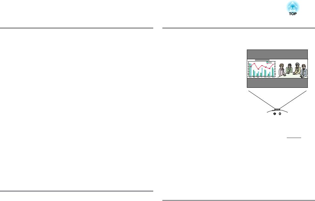
Project two images simultaneously (Split Screen)
You can simultaneously project the images from two video sources lined up on the screen. This increases the range of applications, such as when holding a video conference while projecting presentation materials. s p.34
The split screen function is supported by EB-G5950/G5900/G5650W/G5600.
Clearly reproduce medical images
A color mode called "DICOM SIM" is provided to project medical images, such as X-ray photographs. This mode produces image quality that approaches the DICOMg standard.
(The projector is not a medical device and cannot be used for medical diagnosis.) s p.33
Precise color adjustments
As well as Color Mode, you can also adjust the image's absolute color temperature and the strength of each RGB color. Also, because you can adjust the hue, saturation, and brightness of each RGBCMY, the image can be projected with depth and a color matching in superior detail.
Enhanced Security Functions
Password Protect to restrict and manage users

Projector Features |
|
9 |
|
|
|
By setting a password you can restrict who can use the projector. s p.49
Control Panel lock restricts button operation on the control panel.
You can use this to prevent people changing projector settings without permission at events, in schools, and so on. s p.51
Equipped with various anti-theft devices
The projector is equipped with the following types of anti-theft security devices. s p.52
•Security slot
•Security cable installation point
•Screw to fix the lens unit removal button
Easy to Handle
Direct power On/Off
In places where power is managed centrally, such as in a conference room, the projector can be set to power on and off automatically when the power source to which the projector is connected is switched on or off.
No cool down delay
After turning the projector's power off, you can disconnect the projector's power cable without having to wait for the projector to cool down.
Monitoring and Control Functions
A selection of monitoring and control protocols is supported, such as the Epson EasyMP Monitor application software. This allows you to use the projector according to your system environment. s "Monitoring and Controls" p.110
Taking Full Advantage of a Network Connection (EB-G5950/G5650W only)
Simultaneously project four images for dynamic conferences
By using the supplied EasyMP Multi PC Projection applications software, the images from up to four computers that are connected to the network can be simultaneously displayed. Anyone can freely and easily project images from connected computers to make conferences and meetings more lively. sEasyMP MultiPC Projection Operation Guide
Transferring images and audio using the network
The supplied EasyMP Network Projection applications software can be used to connect to network computers and transfer video, audio, and movies. Using a variety of transfer functions increases presentation possibilities. s EasyMP Network Projection Operation Guide
Project using "Connect to a Network Projector"
By connecting the projector to a network and using the Network Projector function in Windows Vista or Windows 7, multiple users on the network can share the projector. s p.124
Quick wireless connections to easily connect to the network
Network computers can be easily connected to the projector simply by connecting an optional Quick Wireless Connection USB Key. (This function is supported only for Windows computers.) s p.147
Part Names and Functions |
|
10 |
|
|
|
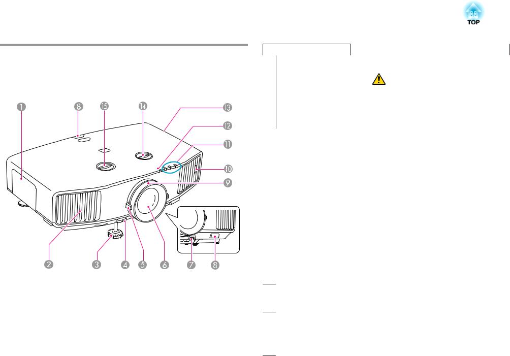
Front/Top
EB-G5950/G5650W with the standard lens is shown in the illustration.
From here on, all features will be explained using illustrations of EBG5950/G5650W with a standard lens unless otherwise specified.
|
Name |
Function |
A |
Lamp cover |
Open this cover when replacing the projector's lamp. |
|
|
s p.104 |
|
|
|
Name |
Function |
B Air exhaust vent |
Exhaust vent for air used to cool the projector internally. |
|
|
Caution |
|
|
|
Do not place objects that may become warped or |
|
|
|
otherwise affected by heat near the Air exhaust vent |
|
|
|
and do not put your face or hands near the vent |
|
|
|
while projection is in progress. |
|
|
|
|
|
|
|
|
|
C Front adjustable foot |
Extend and adjust the position of the projected image |
|
|
|
when the projector is placed on a surface such as a desk. |
|
|
|
s Quick Start Guide |
|
|
|
|
|
|
D Foot adjust lever |
Pull out the foot lever to extend and retract the front foot. |
|
|
|
s Quick Start Guide |
|
|
|
|
|
|
E Zoom ring |
Adjusts the image size. s Quick Start Guide |
|
|
|
|
|
|
F Projection lens |
Images are projected through here. |
|
|
|
|
|
|
G Lens unit removal |
Press this button to remove the lens unit when replacing |
|
|
button |
lens units. s p.141 |
|
|
|
|
|
|
H Remote receiver |
Receives signals from the remote control. s p.19 |
|
|
|
|
|
|
I Focus ring |
Adjusts the image focus. s Quick Start Guide |
|
|
|
|
|
|
J Air filter tab |
When cleaning or replacing the air filter, use this tab to |
|
|
|
pull out the air filter. s p.101, p.107 |
|
|
|
|
|
|
K Status indicators |
The color of the indicators and whether they are flashing |
|
|
|
or lit indicate the status of the projector. s p.87 |
|
|
LWireless LAN indicator This indicator shows the status of network access when the (EB-G5950/G5650W Wireless LAN unit is installed. s p.143
only)
M Air intake vent |
Takes in air to cool the projector internally. If dust collects |
(Air filter) |
here it can cause the internal temperature to rise, and this |
|
can lead to problems with operation and shorten the |
|
optical engine's service life. Be sure to clean the air filter |
|
regularly. s p.101 |
Part Names and Functions |
|
11 |
|
|
|
|
Name |
Function |
N |
Vertical lens shift dial |
Turn the dial to move the position of the projected image |
|
|
up or down. s p.22 |
|
|
|
O |
Horizontal lens shift |
Turn the dial to move the position of the projected image |
|
dial |
left or right. s p.22 |
|
|
|
Base
|
Name |
Function |
B |
Screw holes to fix the |
Holes for screws to fix the cable cover in place. |
|
cable cover |
s p.144 |
|
|
|
C |
Screw hole to fix |
When installing the Wireless LAN unit, use this screw hole |
|
Wireless LAN unit (EB- |
to fix the unit in place to avoid loss and so on. s p.143 |
|
G5950/G5650W only) |
|
|
|
|
D |
Rear foot |
When setup on a desk, turn to extend and retract to adjust |
|
|
the horizontal tilt. s Quick Start Guide |
|
|
|
E |
Security cable |
Pass a commercially available anti-theft wire lock through |
|
installation point |
here when you want to secure the projector to a fixed |
|
|
object. s p.52 |
|
|
|
F |
Handle |
Use these handles when carrying the projector. |
|
|
|
G |
Screw hole for the |
When installing a lens unit, use this screw hole to fix the |
|
screw to fix the lens |
lens unit removal button using the screw supplied. |
|
unit removal button |
s p.52 |
|
|
|
|
Name |
Function |
A |
Ceiling mount fixing |
Attach the optional ceiling mount here when suspending |
|
points |
the projector from a ceiling. s p.147, p.131 |
|
(4 points) |
|
|
|
|
Part Names and Functions |
|
12 |
|
|
|
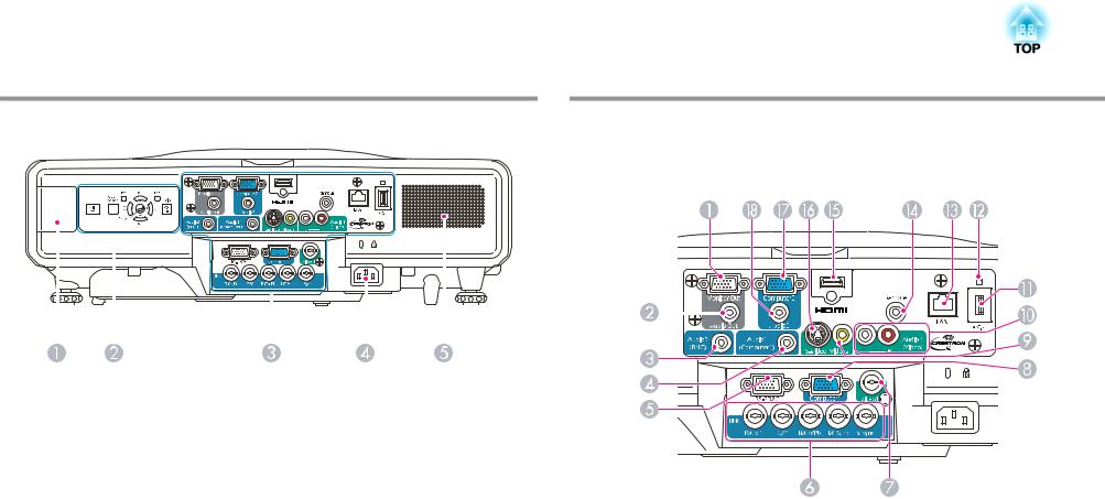
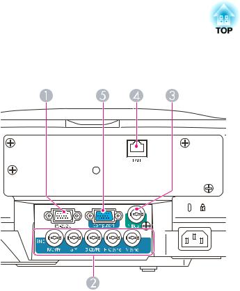
Rear |
Interface |
|
EB-G5950/G5650W |
|
|
|
|
|
|
|
|
|
|
|
|
|
|
|
|
|
|
|
|
|
|
|
|
|
|
|
|
|
|
|
|
|
|
|
|
|
|
|
|
|
|
|
|
|
|
|
|
|
|
|
|
|
|
|
|
|
|
|
|
|
|
|
|
|
|
|
|
|
|
|
|
|
|
|
|
|
|
|
|
|
|
|
|
|
|
|
|
|
|
|
|
|
|
|
|
|
|
|
|
|
|
|
|
|
|
|
|
|
|
|
|
|
|
|
|
|
|
|
|
|
|
|
|
|
|
|
|
|
|
|
|
|
|
|
|
|
|
|
|
|
|
|
|
|
|
|
|
|
|
|
|
|
|
|
|
|
|
|
|
|
|
|
|
|
|
|
|
|
|
|
|
|
|
|
|
|
|
|
|
|
|
|
|
|
|
|
|
|
|
|
|
|
|
|
|
|
|
|
|
|
|
|
|
|
|
|
|
|
|
|
|
|
|
|
|
|
|
|
|
|
|
|
|
|
|
|
|
|
|
|
|
|
|
|
|
|
|
|
|
|
|
|
|
|
|
|
|
|
|
|
|
|
|
Name |
|
Function |
|||||||||||||
A |
Wireless LAN unit |
Install the Wireless LAN unit here. Remove the cover |
|||||||||||||||
|
installation section |
when installing. s "Installing the Wireless LAN Unit |
|||||||||||||||
|
(EB-G5950/G5650W |
(ELPAP03) (EB-G5950/G5650W only)" p.143 |
|||||||||||||||
|
only) |
|
|
|
|
|
|
|
|
|
|
||||||
|
|
|
|
|
|
|
|
|
|
|
|||||||
B |
Control Panel |
s "Control Panel" p.15 |
|||||||||||||||
|
|
|
|
|
|
|
|
|
|
|
|||||||
C |
Interface |
s "Interface" p.12 |
|||||||||||||||
|
|
|
|
|
|
|
|
|
|
|
|||||||
D |
Power inlet |
Connects to the power cable. s Quick Start Guide |
|||||||||||||||
|
|
|
|
|
|
|
|
|
|
|
|
|
|
|
|
||
E |
Speaker (EB-G5950/ |
|
|
|
|
|
|
|
|
|
|
||||||
|
G5900/G5650W/ |
|
|
|
|
|
|
|
|
|
|
||||||
|
G5600 only) |
|
|
|
|
|
|
|
|
|
|
||||||
|
|
|
|
|
|
|
|
|
|
|
|
|
|
|
|
|
|
|
|
|
|
|
|
|
|
|
|
|
|
|
|
|
|
|
|
|
|
|
|
|
|
|
|
|
|
|
|
|
|
|
|
|
|
|
|
|
|
|
|
|
|
|
|
|
|
|
|
|
|
|
|
|
|
|
|
|
|
|
|
|
|
|
|
|
|
|
|
|
|
|
|
|
|
|
|
|
|
|
|
|
|
|
|
|
|
|
|
|
|
|
|
|
|
|
|
|
|
|
|
|
|
|
|
Name |
|
|
|
|
|
Function |
|||||||
A |
Monitor Out port |
|
Outputs to an external monitor the analog RGB signal |
|||||||||||
|
|
|
|
|
from the computer connected to the Computer1 input |
|||||||||
|
|
|
|
|
port, Computer2 input port, or BNC input port. The |
|||||||||
|
|
|
|
|
signals that are input from other ports and component |
|||||||||
|
|
|
|
|
video signals cannot be output. |
|||||||||
|
|
|
|
|
|
|
|
|||||||
B |
Audio Out port |
|
Outputs the sound of the image currently being projected |
|||||||||||
|
|
|
|
|
to external speakers. |
|||||||||
|
|
|
|
|
|
|
|
|||||||
C |
Audio3 input port |
|
Connects to the audio out port of the device that is |
|||||||||||
|
|
|
|
|
connected to the BNC input port. |
|||||||||
|
|
|
|
|
|
|
|
|||||||
D |
Audio1 input port |
|
Connects to the audio out port of the device that is |
|||||||||||
|
|
|
|
|
connected to the Computer1 input port. |
|||||||||
|
|
|
|
|
|
|
|
|
|
|
|
|
|
|
Part Names and Functions |
|
13 |
|
|
|
|
Name |
|
|
Function |
E |
RS-232C port |
When controlling the projector from a computer, connect |
||
|
|
it to the computer with an RS-232C cable. This port is for |
||
|
|
control use and should not normally be used. |
||
|
|
s "ESC/VP21 Commands" p.116 |
||
|
|
|
||
F |
BNC input port |
For analog RGB signals from a computer and component |
||
|
|
video signals from other video sources. |
||
|
|
|
||
G |
Video1 input port |
For composite video signals from video sources. |
||
|
|
|
||
H |
Computer1 input port |
For analog RGB signals from a computer and component |
||
|
|
video signals from other video sources. |
||
|
|
|
||
I |
Video2 input port |
For composite video signals from video sources. |
||
|
|
|
||
J |
Audio4 input port |
Connects to the audio out port when you want to output |
||
|
|
audio from the projector from equipment connected to |
||
|
|
the S-Video input port, Video1 input port, or Video2 |
||
|
|
input port. |
||
|
|
|
||
K |
USB(TypeA) port |
Connects a USB storage device or a digital camera, and |
||
|
|
projects image/movie files and scenarios. s PC Free |
||
|
|
Operation Guide |
||
|
|
|
||
L |
USB indicator |
The following explains the status of USB devices |
||
|
|
connected to USB(TypeA) port. |
||
|
|
OFF: USB device is not connected |
||
|
|
Orange Light ON: USB device is connected |
||
|
|
Green Light ON: USB device is operating |
||
|
|
Red Light ON: Error |
||
|
|
|
||
M |
LAN port |
Connects a LAN cable to connect to a network. |
||
|
|
|
||
N |
Remote port |
Connects the optional remote control cable set and inputs |
||
|
|
signals from the remote control. When the remote control |
||
|
|
cable is plugged into this remote port, the remote receiver |
||
|
|
on the projector is disabled. |
||
|
|
|
||
O |
HDMI input port |
Inputs video signals from HDMI™ compatible video |
||
|
|
equipment and computers. This projector is compatible |
||
|
|
with HDCPgsignals. |
||
|
|
|
|
|
P |
S-Video input port |
For S-video signals from video sources. |
||
|
|
|
|
|
|
Name |
Function |
Q |
Computer2 input port |
For analog RGB signals from a computer and component |
|
|
video signals from other video sources. |
|
|
|
R |
Audio2 input port |
Connects to the audio out port of the device that is |
|
|
connected to the Computer2 input port. |
|
|
|
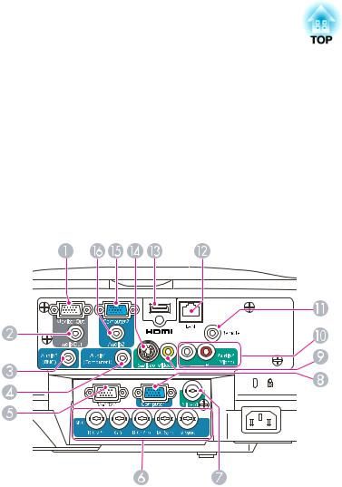
EB-G5900/G5600
|
Name |
Function |
A |
Monitor Out port |
Outputs to an external monitor the analog RGB signal |
|
|
from the computer connected to the Computer1 input |
|
|
port, Computer2 input port, or BNC input port. The |
|
|
signals that are input from other ports and component |
|
|
video signals cannot be output. |
|
|
|
B |
Audio Out port |
Outputs the sound of the image currently being projected |
|
|
to external speakers. |
|
|
|
Part Names and Functions |
|
14 |
|
|
|
|
Name |
|
|
Function |
C |
Audio3 input port |
Connects to the audio out port of the device that is |
||
|
|
connected to the BNC input port. |
||
|
|
|
||
D |
Audio1 input port |
Connects to the audio out port of the device that is |
||
|
|
connected to the Computer1 input port. |
||
|
|
|
||
E |
RS-232C port |
When controlling the projector from a computer, connect |
||
|
|
it to the computer with an RS-232C cable. This port is for |
||
|
|
control use and should not normally be used. |
||
|
|
s "ESC/VP21 Commands" p.116 |
||
|
|
|
||
F |
BNC input port |
For analog RGB signals from a computer and component |
||
|
|
video signals from other video sources. |
||
|
|
|
||
G |
Video1 input port |
For composite video signals from video sources. |
||
|
|
|
||
H |
Computer1 input port |
For analog RGB signals from a computer and component |
||
|
|
video signals from other video sources. |
||
|
|
|
||
I |
Video2 input port |
For composite video signals from video sources. |
||
|
|
|
||
J |
Audio4 input port |
Connects to the audio out port when you want to output |
||
|
|
audio from the projector from equipment connected to |
||
|
|
the S-Video input port, Video1 input port, or Video2 |
||
|
|
input port. |
||
|
|
|
||
K |
Remote port |
Connects the optional remote control cable set and inputs |
||
|
|
signals from the remote control. When the remote control |
||
|
|
cable is plugged into this remote port, the remote receiver |
||
|
|
on the projector is disabled. |
||
|
|
|
||
L |
LAN port |
Connects a LAN cable to connect to a network. |
||
|
|
|
||
M |
HDMI input port |
Inputs video signals from HDMI™ compatible video |
||
|
|
equipment and computers. This projector is compatible |
||
|
|
with HDCPgsignals. |
||
|
|
|
|
|
N |
S-Video input port |
For S-video signals from video sources. |
||
|
|
|
||
O |
Computer2 input port |
For analog RGB signals from a computer and component |
||
|
|
video signals from other video sources. |
||
|
|
|
||
P |
Audio2 input port |
Connects to the audio out port of the device that is |
||
|
|
connected to the Computer2 input port. |
||
|
|
|
|
|
EB-G5800/G5500
|
Name |
Function |
A |
RS-232C port |
When controlling the projector from a computer, connect |
|
|
it to the computer with an RS-232C cable. This port is for |
|
|
control use and should not normally be used. |
|
|
s "ESC/VP21 Commands" p.116 |
|
|
|
B |
BNC input port |
For analog RGB signals from a computer and component |
|
|
video signals from other video sources. |
|
|
|
C |
Video1 input port |
For composite video signals from video sources. |
|
|
|
D |
LAN port |
Connects a LAN cable to connect to a network. |
|
|
|
E |
Computer1 input port |
For analog RGB signals from a computer and component |
|
|
video signals from other video sources. |
|
|
|
Part Names and Functions |
|
15 |
|
|
|
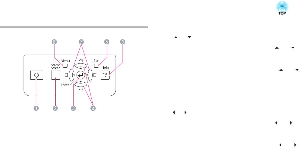
Control Panel
|
|
|
|
|
|
|
|
|
|
|
|
|
|
|
|
|
|
|
Name |
Function |
|||
A |
[t] button |
Turns the projector power On or Off. s Quick Start |
|||
|
|
|
|
|
Guide |
B |
[Source Search] |
Changes to the next input source that is connected to the |
|||
|
button |
projector and is sending an image. s p.27 |
|||
|
|
|
|
|
|
C |
[Enter] button |
If pressed during projection of computer analog RGB |
|||
|
|
|
|
|
signals, it automatically adjusts the Tracking, Sync., and |
|
|
|
|
|
Position to project the optimum image. |
|
|
|
|
|
When the configuration menu or a Help screen is |
|
|
|
|
|
displayed, it accepts and enters the current selection and |
|
|
|
|
|
moves to the next level. s p.54 |
|
|
|
|
|
|
|
|
Name |
|
Function |
|
|
D |
[w/ |
][v/ |
] |
Corrects vertical keystone distortion. s p.25 |
|
|
|
button |
|
If pressed while the configuration menu or a Help screen is |
|||
|
|
|
|
displayed, these buttons only have the [ |
] and [ |
] |
|
|
|
|
functions which select menu items and setting values. |
||
|
|
|
|
s p.54 |
|
|
|
|
|
|
When projecting using PC Free or Connect to a Network |
||
|
|
|
|
Projector, these buttons function only as [ |
] and [ |
] |
|
|
|
|
buttons. (EB-G5950/G5650W) |
|
|
|
|
|
||||
E |
[Help] button |
Displays and closes the Help screen which shows you how |
||||
|
|
|
|
to deal with problems if they occur. s p.85 |
|
|
|
|
|
|
|
|
|
F |
[Esc] button |
|
Stops the current function. |
|
|
|
|
|
|
|
If pressed when the configuration menu is displayed, it |
||
|
|
|
|
moves to the previous menu level. s p.54 |
|
|
|
|
|
|
|
|
|
G |
[</ |
][>/ |
] button |
Corrects horizontal keystone distortion. s p.25 |
|
|
|
|
|
|
If pressed while the configuration menu or a Help screen is |
||
|
|
|
|
displayed, these buttons only have the [ ] and [ ] |
|
|
|
|
|
|
functions which select menu items and setting values. |
||
|
|
|
|
s p.54 |
|
|
|
|
|
|
When projecting using PC Free or Connect to a Network |
||
|
|
|
|
Projector, these buttons function only as [ |
] and [ |
] |
|
|
|
|
buttons. (EB-G5950/G5650W) |
|
|
|
|
|
|
|||
H |
[Menu] button |
Displays and closes the configuration menu. |
|
|||
|
|
|
|
s p.53 |
|
|
|
|
|
|
|
|
|
Part Names and Functions
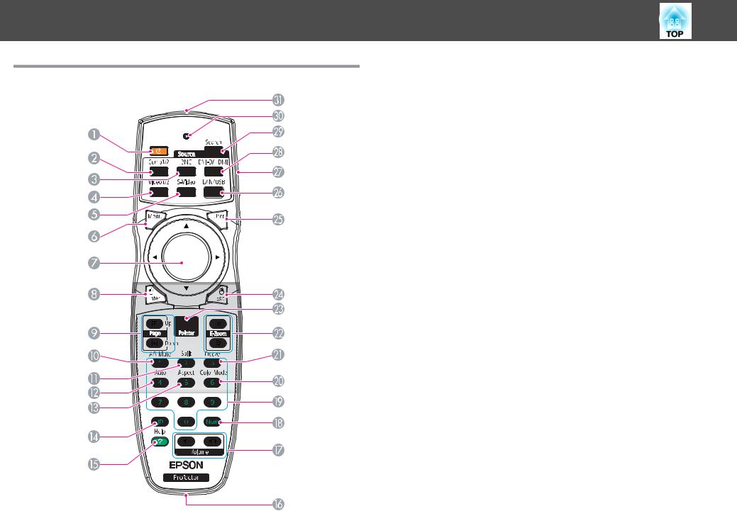
Remote Control
16
|
Name |
Function |
A |
[t] button |
Turns the projector power On or Off. s Quick Start |
|
|
Guide |
|
|
|
B |
[Comp1/2] button |
Each time the button is pressed, the image displayed |
|
|
changes between the Computer1 input port and |
|
|
Computer2 input port. (EB-G5950/G5900/G5650W/ |
|
|
G5600) |
|
|
Changes to images from the Computer1 input port. (EB- |
|
|
G5800/G5500) |
|
|
|
C |
[BNC] button |
Changes to images from the BNC input port. |
|
|
|
D |
[Video1/2] button |
Each time the button is pressed, the image displayed |
|
|
changes between Video1 input port and Video2 input |
|
|
port. (EB-G5950/G5900/G5650W/G5600) |
|
|
Changes to images from the Video1 input port. (EB- |
|
|
G5800/G5500) |
|
|
|
E |
[S-Video] button |
Changes to images from the S-video input port.(EB- |
|
|
G5950/G5900/G5650W/G5600 only) |
|
|
This button does not function when using EB-G5800/ |
|
|
G5500. |
|
|
|
F |
[Menu] button |
Displays and closes the configuration menu. s p.53 |
|
|
|
G |
[h] button |
When the configuration menu or Help screen is displayed, |
|
|
it selects menu items and setting values. s p.54, |
|
|
p.85 |
|
|
When using the optional wireless mouse receiver, the |
|
|
pointer moves in the direction (eight possible directions) |
|
|
that the button is pressed. |
|
|
|
H |
[Enter] button |
When the configuration menu or a Help screen is |
|
|
displayed, it accepts and enters the current selection and |
|
|
moves to the next level. s p.54, p.85 |
|
|
Acts as a mouse's left button when using the optional |
|
|
wireless mouse receiver. |
|
|
|
Part Names and Functions |
|
17 |
|
|
|
|
Name |
|
|
Function |
I |
[Page] buttons |
These buttons can be used to page up and down when |
||
|
[[][]] |
projecting an image from a computer that is connected to |
||
|
|
the projector through the network. These buttons can be |
||
|
|
used to switch the screen when projecting with PC Free. |
||
|
|
(EB-G5950/G5650W only) |
||
|
|
These buttons can be used to page up and down when |
||
|
|
using the optional wireless mouse receiver. |
||
|
|
|
||
J |
[A/V Mute] button |
Turns the video and audio on or off. (EB-G5950/G5900/ |
||
|
|
G5650W/G5600) |
||
|
|
Turns the video on or off. (EB-G5800/G5500) s p.38 |
||
|
|
|
||
K |
[Split] button |
Press this button to split the screen in two and project two |
||
|
|
images simultaneously. s p.34 |
||
|
|
This button does not function when using EB-G5800/ |
||
|
|
G5500. |
||
|
|
|
||
L |
[Auto] button |
If pressed during projection of computer analog RGB |
||
|
|
signals, it automatically adjusts the Tracking, Sync., and |
||
|
|
Position to project the optimum image. |
||
|
|
|
|
|
M |
[Aspect] button |
The |
Aspect Ratio |
gchanges each time the button is |
|
|
pressed. s p.29 |
||
|
|
|
||
N |
[ID] button |
Press to set the remote control ID. s p.43 |
||
|
|
|
||
O |
[Help] button |
Displays and closes the Help screen which shows you how |
||
|
|
to deal with problems if they occur. s p.85 |
||
|
|
|
||
P |
Remote port |
Connects the optional remote control cable set and |
||
|
|
outputs signals from the remote control. (EB-G5950/ |
||
|
|
G5900/G5650W/G5600 only) |
||
|
|
When the remote control cable is plugged into this remote |
||
|
|
port, the remote receiver is disabled. |
||
|
|
|
|
|
Name |
Function |
Q [Volume] button |
[ ] Decreases the volume. [ ] Increases the volume. |
[ ][ ] |
s Quick Start Guide |
|
This button does not function when using EB-G5800/ |
|
G5500. |
|
|
Caution |
|
|
|
Do not start when the volume is set too high. |
|
|
|
Loud sounds may cause loss of hearing. Always low- |
|
|
|
er the volume before turning off the projector. Grad- |
|
|
|
ually increase the volume after turning on the pro- |
|
|
|
jector. |
|
|
|
|
|
|
|
|
|
R [Num] button |
Use this button to enter passwords, IP Address from the |
|
|
|
Network, and so on. |
|
|
|
|
|
|
S Numeric buttons |
Use this button to enter passwords, remote control ID |
|
|
|
settings, IP Address from the Network, and so on. |
|
|
|
|
|
|
T [Color Mode] button |
Each time the button is pressed, the Color Mode changes. |
|
|
|
s p.33 |
|
|
|
|
|
|
U [Freeze] button |
Images are paused or unpaused. s p.38 |
|
|
|
|
|
|
V [E-Zoom] buttons |
The [z] button enlarges the image without changing the |
|
|
[z][x] |
projection size. |
|
|
|
The [x] button reduces the parts of images that have been |
|
|
|
enlarged using the [z] button. s p.40 |
|
|
|
|
|
|
W [Pointer] button |
Press to activate the on screen pointer. s p.39 |
|
|
|
|
|
|
X [Esc] button |
Stops the current function. If pressed when the |
|
|
|
configuration menu is displayed, it moves to the previous |
|
|
|
menu level. s p.54 |
|
|
|
Acts as a mouse's right button when using the optional |
|
|
|
wireless mouse receiver. |
|
|
Part Names and Functions |
|
18 |
|
|
|
|
Name |
Function |
Y |
[User] button |
Press to assign a frequently used item from the six |
|
|
available configuration menu items. By pressing the |
|
|
button the assigned menu item selection/adjustment |
|
|
screen is displayed, allowing you to make one-touch |
|
|
settings/adjustments. s p.59 |
|
|
Test Pattern is assigned as the default setting. |
|
|
|
Z |
[LAN/USB] button |
Each time you press this button, the image is switched |
|
|
between the image from a computer that is connected to |
|
|
the projector through the network and the image from the |
|
|
USB device that is connected to the USB(TypeA) port. |
|
|
(EB-G5950/G5650W only) |
|
|
This button does not function when using EB-G5900/ |
|
|
G5800/G5600/G5500. |
|
|
|
a |
ID switch |
Use this switch to enable (On)/disable (Off) ID settings for |
|
|
the remote control. s p.42 |
|
|
|
b |
[DVI-D/HDMI] button |
Changes to images from the HDMI input port. (EB- |
|
|
G5950/G5900/G5650W/G5600 only) |
|
|
This button does not function when using EB-G5800/ |
|
|
G5500. |
|
|
|
c |
[Source Search] |
Changes to the next input source that is connected to the |
|
button |
projector and is sending an image. s p.27 |
|
|
|
d |
Indicators |
A light is emitted when outputting remote control signals. |
|
|
|
e |
Remote control light- |
Outputs remote control signals. |
|
emitting area |
|
|
|
|
Installing the batteries
Attention
Make sure you read the Safety Instructions before handling the batteries. s Safety Instructions
Procedure
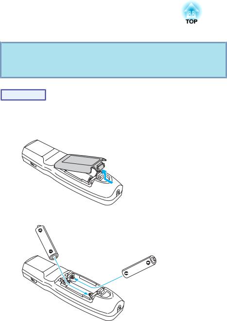
A Remove the battery cover.
While pushing the battery compartment cover catch, lift the cover up.
B Insert the batteries in the correct direction.
The batteries are not set in the remote control when it is sold. Set the supplied batteries (two, AA alkaline batteries) to use the remote control.
Part Names and Functions |
|
19 |
|
|
|
Caution
Check the positions of the (+) and (-) marks inside the battery holder to ensure the batteries are inserted the correct way.
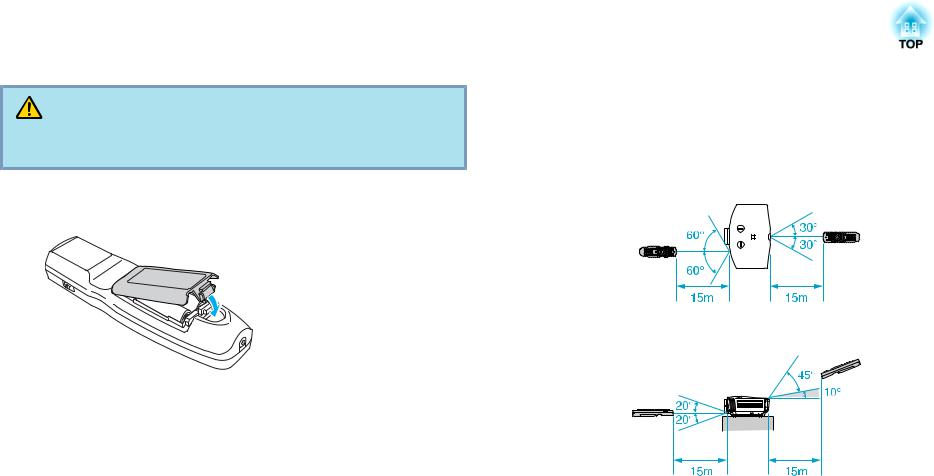
C Replace the battery cover.
Press the battery compartment cover until it clicks into place.
If delays in the responsiveness of the remote control occur or if it does not operate after it has been used for some time, it probably means that the batteries are becoming flat. When this happens, replace them with new batteries. Have two AA size alkaline batteries ready. You cannot use other batteries except for the AA size alkaline.
Operating range of remote control
When using the remote control, point the remote control light-emitting area at the remote receiver on the projector. The operating range of the remote control that is provided with the projector is shown below.
Horizontal operating range
Vertical operating range
q |
• To restrict reception of the operation signals from the remote |
control, set the Remote Receiver on the Set menu. s p.59 |
|
|
• When using a remote control provided with other Epson projectors, |
|
set the Remote Control Type on the Extended menu. s p.61 |
|
The operating range will depend on the remote control that you |
|
use. |
|
|

Useful Functions
This chapter explains useful tips for giving presentations, and the security functions.

Adjusting the Projected Image
Displaying a Test Pattern
A test pattern can be displayed to adjust the projection status without connecting video equipment. This is useful when installing a projector.
q If the [User] button on the remote control is set to Test Pattern, the test pattern will be displayed when the [User] button is pressed. (The default setting is Test Pattern.)
Procedure
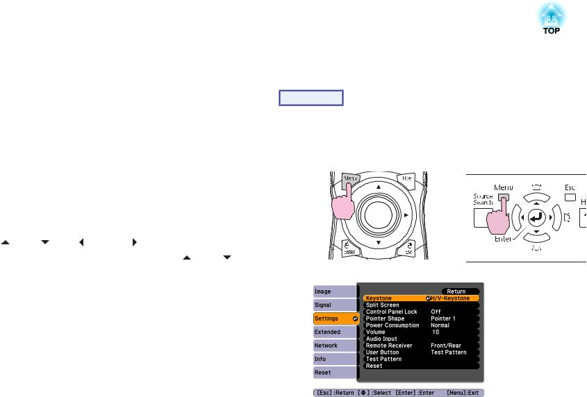
A Press the [Menu] button while the projector is projecting.
Select Settings - "Test Pattern", then press the [Enter] button.
Using the Remote Control |
Using the Control panel |
21
B Press the [h] button on the remote control in the [r] direction or press the [Enter] button on the control panel to switch the test pattern.
To display the previous image, press the [h] button on the remote control in the [l] direction.
Using the Remote Control |
Using the Control panel |
The following adjustments can be made while the test pattern is being displayed.
•Zoom and focus adjustment s Quick Start Guide
•Projected image position adjustment s p.22
•Projected image keystone correction s p.22
•Selecting the projection quality (Selecting Color Mode) s p.33
•Brightness adjuctment s Image menu - Brightness p.55
•Sharpness adjustment (Standard only) s Image menu - Sharpness p.55
•Color temperature adjustment s Image menu - Abs. Color Temp. p.55
•Color adjustment s Image menu - Color Adjustment p.55
Adjusting the Projected Image |
|
22 |
|
|
|
q To set menu items that cannot be set while the test pattern is being displayed or to fine-tune the projected image, project an image from the connected device.
C Press the [Esc] button to end the test pattern.
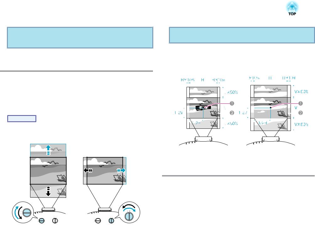
Adjusting the Position of the Projected Image
(Lens Shift)
The lens can be shifted to adjust the position of the projected image, for example, when the projector cannot be installed directly in front of the screen.
Procedure
Turn the vertical lens shift dial or horizontal lens shift dial on the projector to adjust the location of the projected image.
q The image will be clearest when both the vertical and horizontal lens shift dials are set in the center.
The ranges within which the image can be moved using the lens shift dials are shown below.
EB-G5950/G5900/G5800/G5600/ |
|
|
EB-G5650W |
|
|
|
|
|||||||||||||||||||||||||||
|
|
|
|
|
|
|
|
G5500 |
|
|
|
|
|
|
|
|
|
|
|
|
||||||||||||||
|
|
|
|
|
|
|
|
|
|
|
|
|
|
|
|
|
|
|
|
|
|
|
|
|
|
|
|
|
|
|
|
|
|
|
|
|
|
|
|
|
|
|
|
|
|
|
|
|
|
|
|
|
|
|
|
|
|
|
|
|
|
|
|
|
|
|
|
|
|
|
|
|
|
|
|
|
|
|
|
|
|
|
|
|
|
|
|
|
|
|
|
|
|
|
|
|
|
|
|
|
|
|
|
|
|
|
|
|
|
|
|
|
|
|
|
|
|
|
|
|
|
|
|
|
|
|
|
|
|
|
|
|
|
|
|
|
|
|
|
|
|
|
|
|
|
|
|
|
|
|
|
|
|
|
|
|
|
|
|
|
|
|
|
|
|
|
|
|
|
|
|
|
|
|
|
|
|
|
|
|
|
|
|
|
|
|
|
|
|
|
|
|
|
|
|
|
|
|
|
|
|
|
|
|
|
|
|
|
|
|
|
|
|
|
|
|
|
|
|
|
|
|
|
|
|
|
|
|
|
|
|
|
|
|
|
|
|
|
|
|
|
|
|
|
|
|
|
|
|
|
|
|
|
|
|
|
|
|
|
|
|
|
|
|
|
|
|
|
|
|
|
|
|
|
|
|
|
|
|
|
|
|
|
|
|
|
|
|
|
|
|
|
|
|
|
|
|
|
|
|
|
|
|
|
|
|
|
|
|
|
|
|
|
|
|
|
|
|
|
|
|
|
|
|
|
|
|
|
|
|
|
|
|
|
|
|
|
|
|
|
|
|
|
|
|
|
|
|
|
|
|
|
|
|
|
|
|
|
|
|
|
|
|
|
|
|
|
|
|
|
|
|
|
|
|
|
|
|
|
|
|
|
|
|
|
|
|
|
|
|
|
|
|
|
|
|
|
|
|
|
|
|
|
|
|
|
|
|
|
|
|
|
|
|
|
|
|
|
|
|
|
|
|
|
|
|
|
|
|
|
|
|
|
|
|
|
|
|
|
|
|
|
|
|
|
|
|
|
|
|
|
|
|
|
|
|
|
|
|
|
|
|
|
|
|
|
|
|
|
|
|
|
|
|
|
|
|
|
|
|
|
|
|
|
|
|
|
|
|
|
|
|
|
|
|
|
|
|
|
|
|
|
|
|
|
|
|
|
|
|
|
|
|
|
|
|
|
|
|
|
|
|
|
|
|
|
|
|
|
|
|
|
|
|
|
|
|
|
|
|
|
|
|
|
|
|
|
|
|
|
|
|
|
|
|
|
|
|
|
|
|
|
|
|
|
|
|
|
|
|
|
|
|
|
|
|
|
|
|
|
|
|
|
|
|
|
|
|
|
|
|
|
|
|
|
|
|
|
|
|
|
|
|
|
|
|
|
|
|
|
|
|
|
|
|
|
|
|
|
|
|
|
|
|
|
|
|
|
|
ACenter of lens
BProjected image when lens shift dials are set in the center
Correcting Distortion in the Projected Image
There are two methods of correcting distortion in projected images as below.
Adjusting the Projected Image |
|
23 |
|
|
|
•Quick Corner
This allows you to manually correct each of the four corners of the projected image separately. s "Quick Corner" p.23
We recommend using Quick Corner to accurately adjust keystone distortion.
•H/V-Keystone
This allows you to manually correct distortion in the horizontal and vertical directions independently. You can perform easy H/V-Keystone
corrections by using the [w/ ], [v/
 ], [</
  ] and [>/
  ] buttons on the projector's control panel. s "H/V-Keystone" p.25
Quick Corner and horizontal and vertical keystone cannot be performed at the same time. When the Keystone correction method is selected from the Configuration menu, the correction method you choose is assigned to the
control |
panel [w/ ], |
[v/ |
], [</ ] and [>/ ] buttons. |
The |
default |
setting |
for Keystone is |
set to |
H/V-Keystone, so when [w/ |
], |
[v/ ], |
[</  ] and [>/
  ] buttons are pressed, H/V-Keystone correction is carried out.
Because Quick Corner and H/V-Keystone correction can be carried out while projecting a test pattern, you do not need to make preparations by connecting a computer or other equipment.
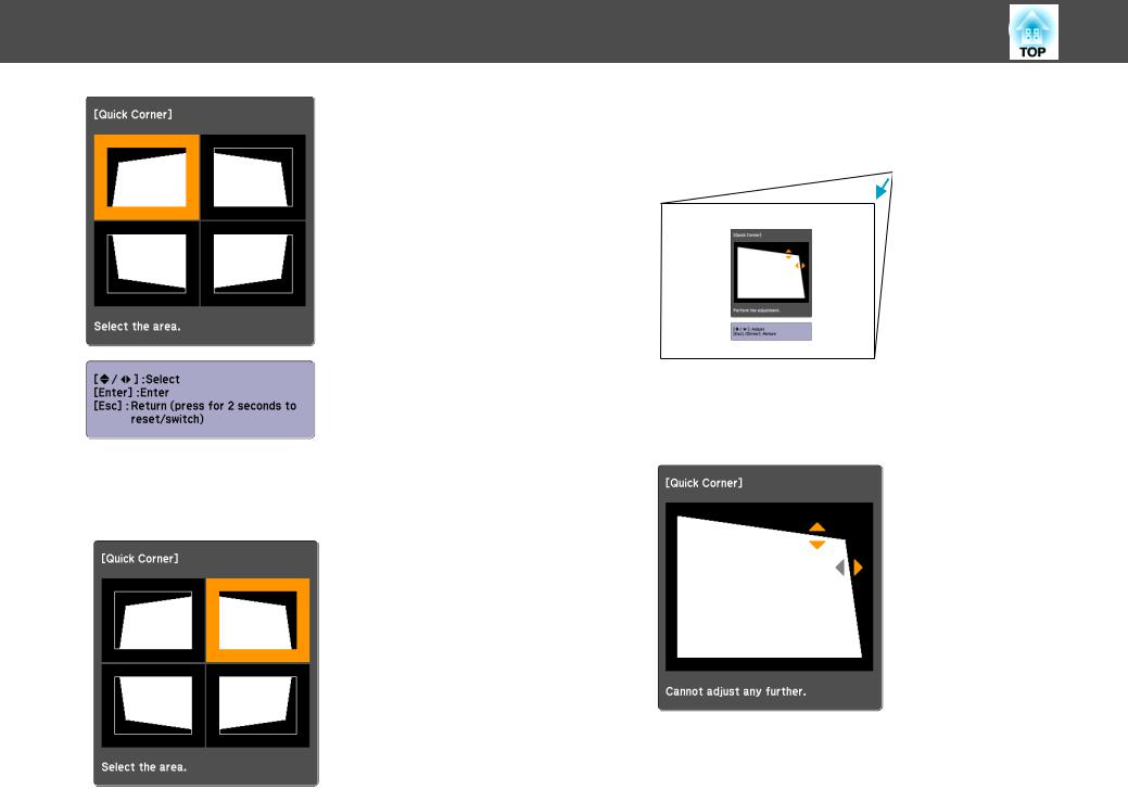
Quick Corner
Procedure
A Press the [Menu] button while the projector is projecting.
Select Settings menu - "Keystone" and then press the [Enter] button. s "Using the Configuration Menu" p.54
Using the Remote Control |
Using the Control panel |
B Select "Quick Corner", and then press the [Enter] button.
Press the [Enter] button again to display the selection screen from which you can select one of four corners.
Adjusting the Projected Image
C Use the [h] button on the remote control or the [w/ ], [v/
  ], [</
  ] and [>/
  ] buttons on the control panel to select the corner you want to adjust, and then press the [Enter] button.
24
D Correct the position of the corner using the [h] button on the remote control, or the [w/ ], [v/
 ], [</
  ] and [>/
  ] buttons on the control panel.
If the triangle in the direction you are adjusting the shape turns gray, as shown in the screenshot below, you cannot adjust the shape any further in that direction.
E Repeat procedures 3 and 4 as needed to adjust any remaining corners.
Adjusting the Projected Image
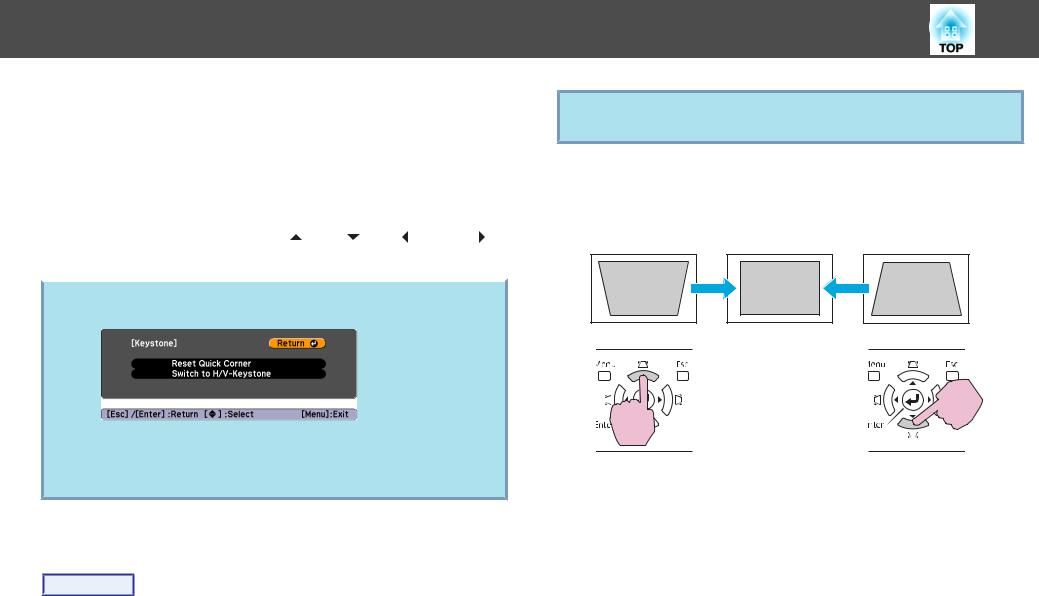
F When you are done, press the [Esc] button to exit the correction menu.
Because the correction method was changed to Quick Corner from Keystone in the configuration menu, when [w/ ], [v/
  ], [</
  ] and [>/
  ] buttons are pressed later, the screen for selecting the corner in procedure 2 is displayed. Change Keystone from the configuration menu to H/V-Keystone if you want to correct H/V-
Keystone when pressing the [w/ |
], [v/ |
], [</ |
] and [>/ ] |
buttons on the control panel. s p.59 |
|
|
|
|
|||
If the [Esc] button is held down for about two seconds while |
|||
q correcting with Quick Corner, the |
following |
screen is |
displayed. |
Reset Quick Corner: Resets the result of Quick Corner corrections.
Switch to H/V-Keystone: Switches the correction method to H/V- Keystone. s "H/V-Keystone" p.25
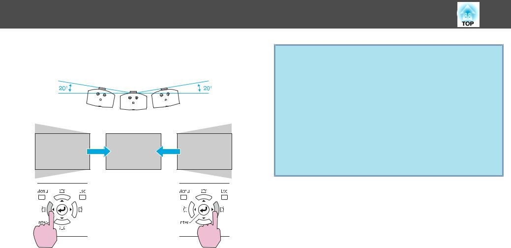
H/V-Keystone
Procedure
Press the [w/ ], [v/
 ], [</
  ] and [>/
  ] buttons on the control panel to adjust keystone settings in the horizontal and vertical directions independently.
25
q This adjustment can also be made from H/V-Keystone on the Settings menu. s p.59
•Correcting vertical keystone
Vertical keystone can be corrected to a vertical projector tilt of up to 40˚ against the screen. If you use the projector tilted at an angle of more than 30˚ it could be damaged and cause an accident.
If the [w/ ] and [v/
 ] buttons are pressed simultaneously for at least 1 second, the value of vertical keystone will return to the original status.
Adjusting the Projected Image
•Correcting horizontal keystone
Horizontal keystone can be corrected to a horizontal projector tilt of up to 20˚.
If the [</  ] and [>/
  ] buttons are pressed simultaneously for at least 1 second, the value of horizontal keystone will return to the original status.
26
q Shift the lens to the position shown below when performing horizontal and vertical keystone. When the lens shift is not positioned as below, the distortion is not corrected accurately. s "Adjusting the Position
of the Projected Image (Lens |
Shift)" |
p.22 |
|||
• The |
horizontal lens shift |
is |
set |
to the center. |
|
• The |
vertical lens shift is |
set to |
the |
top or bottom. |
|
The correction may not be properly performed according to the zoom adjustment value. And, the projected screen size may become smaller after performing the correction. Be careful about the projection distance when installing the projector.
Correct the image using Quick Corner to precisely align the projected image with the screen or to fine-tune the image. s "Quick Corner" p.23
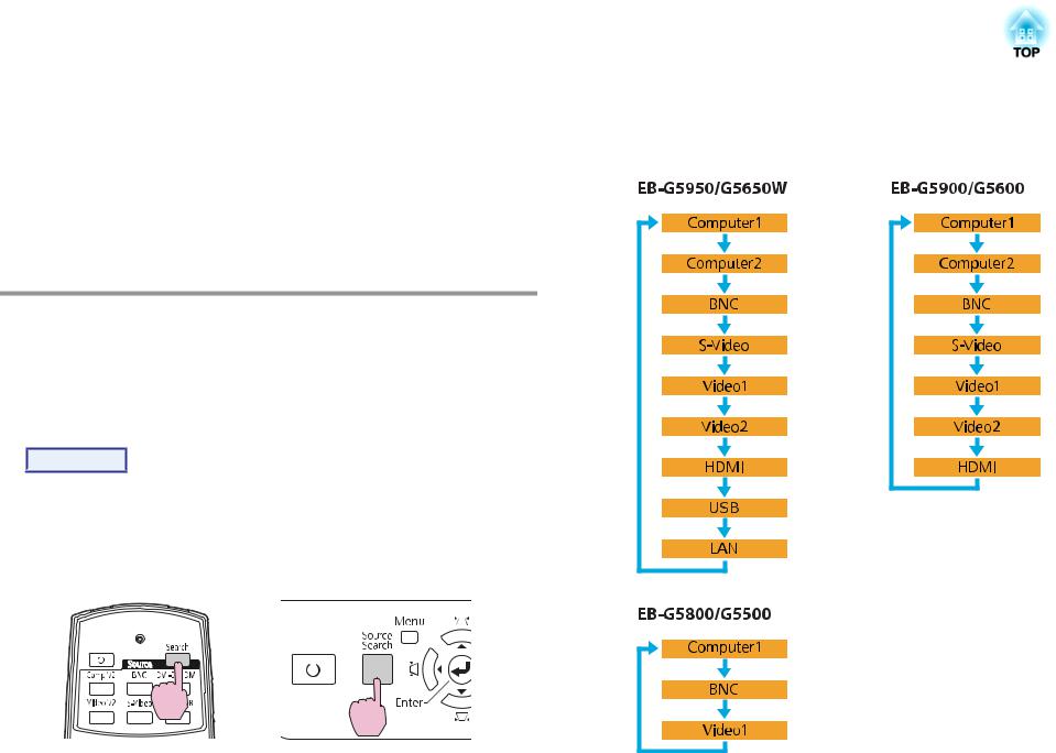
Changing the Projected Image |
|
27 |
|
|
|
You can change the projected image in the following two ways.
•Changing by Source Search
The projector automatically detects signals being input from connected equipment, and the image being input from the input port is projected.
•Changing directly to the target image
You can use the remote control buttons to change to the target input port.
Automatically Detect Input Signal and Change the Projected Image (Source Search)
You can project the target images quickly by pressing the [Source Search] button because it will switch only to images from input ports to which image signals are being input.
Procedure
When your video equipment is connected, start playback before beginning this operation. When two or more pieces of equipment are connected, press the [Source Search] button until the target image is projected.
Using the Remote Control |
Using the Control panel |
||||||
|
|
|
|
|
|
|
|
|
|
|
|
|
|
|
|
|
|
|
|
|
|
|
|
|
|
|
|
|
|
|
|
When the [Source Search] button is pressed, a search is made for input ports to which video signals are being input in the following order. (The input port where no image signal is being input is skipped.)
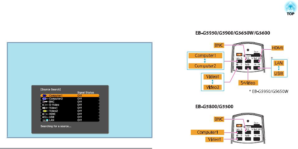
Changing the Projected Image |
|
28 |
|
|
|
When switching to LAN, images from computers connected through the network are projected. (EB-G5950/G5650W only)
q The following screen showing the status of image signals remains displayed when only the image that the projector is currently displaying is available, or when no image signal can be found. You can select the input port where the equipment you want to use is connected. If no operation is performed after about 10 seconds, the screen closes.
Example: EB-G5950/G5650W
Switch to the Target Image by Remote Control
You can change directly to the image from the target input port by pressing the following buttons on the remote control. s "Remote Control" p.16
When switching to LAN, images from computers connected through the network are projected. (EB-G5950/G5650W only)
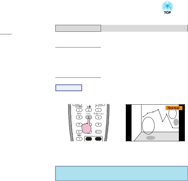
Changing the Aspect Ratio of the Projected Image |
|
29 |
|
|
|
You can select the aspect mode according to the type of input signal, ratio of height and width, and resolution to switch the Aspect Ratiog of the projected image. The aspect modes are listed below. The aspect modes that can be set depend on the type of image that is being projected.
EB-G5950/G5900/G5800/G5600/G5500
Aspect mode |
Explanation |
Normal |
Projects to the full projection size retaining the aspect |
|
ratio of the input image. |
|
|
Auto |
Projects in an appropriate aspect ratio based on |
|
information from the signal being input. |
|
|
4:3 |
Projects to the full projection size at an Aspect of 4:3. |
|
This is ideal for when you want to project images at an |
|
aspect of 5:4 (1280 x 1024) to the full projection size. |
|
|
16:9 |
Projects at a 16:9 aspect ratio. This is ideal for projecting |
|
at full screen size when using a 16:9 screen. |
|
|
Native |
Projects at the resolution of the input image size to the |
|
center of the screen. This is ideal for projecting clear |
|
images. |
|
If the image resolution exceeds the panel resolution |
|
(1024 x 768) of the projector, the edges of the image are |
|
not projected. |
|
|
EB-G5650W
Aspect mode |
Explanation |
Normal |
Projects to the full projection size retaining the aspect |
|
ratio of the input image. |
|
|
Auto |
Projects in an appropriate aspect ratio based on |
|
information from the signal being input. |
|
|
16:9 |
Projects to the full projection size at an aspect ratio of |
|
16:9. |
|
|
Full |
Project at full size. |
|
|
Aspect mode |
Explanation |
Zoom |
Projects the input image enlarged to the full lateral |
|
direction size as the aspect ratio remains. Parts that |
|
extend beyond the projection size are not projected. |
Native |
Projects at the resolution of the input image size to the |
|
center of the screen. This is ideal for projecting clear |
|
images. |
|
If the image resolution exceeds the panel resolution |
|
(1200 x 800) of the projector, the edges of the image are |
|
not projected. |
Procedure
Remote Control
The aspect mode name is displayed on the screen by pressing the button. If you press the button while the aspect mode name is displayed on the screen, it changes to the next aspect mode.
q The aspect mode can also be set using Aspect in the Signal menu from the configuration menu. s p.57
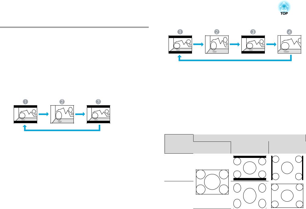
Changing the Aspect Ratio of the Projected Image |
|
30 |
|
|
|
Changing the Aspect Mode (EB-G5950/G5900/
G5800/G5600/G5500)
Projecting images from video equipment
Each time the [Aspect] button on the remote control is pressed, the aspect mode changes in the order Auto, 4:3 and 16:9. s p.29
When inputting a 720p/1080i signal and the aspect mode is set to 4:3, a 4:3 zoom will be applied (the right and left sides of the image will be cut off).
Example: 720p signal input (resolution: 1280x720, aspect ratio: 16:9)
AAuto
B4:3
C16:9
Projecting images from the HDMI input port (EB-G5950/G5900/ G5600 only)
Each time the [Aspect] button on the remote control is pressed, the aspect mode changes in the order Auto, 4:3, 16:9, and Native. s p.29
Example: 1080p signal input (resolution: 1920x1080, aspect ratio: 16:9)
AAuto
B4:3
C16:9
DNative
Projecting images from a computer
Each time the [Aspect] button on the remote control is pressed, the aspect mode changes in the order Normal, 4:3, 16:9, and Native. s p.29
Projection examples for each aspect mode are shown below.
Aspect mode |
Input Signal |
|
XGA |
WXGA |
SXGA |
1024X768(4:3) |
1280X800(16:10) |
1280X1024(5:4) |
Normal |
|
|
4:3
 Loading...