


Instruction Manual |
1052 Size 20 Actuator (H) |
D100323X012 |
September 2012 |
|
|
Fisherr 1052 Size 20 Diaphragm Rotary Actuator with H Mounting Adaptation
Contents |
|
|
|
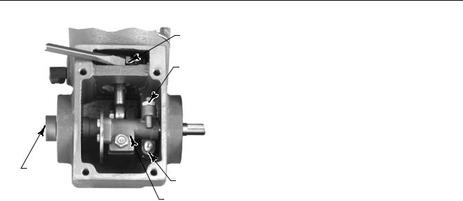
Figure 1. Fisher 1052 Size 20 Actuator |
|
Introduction |
1 |
with H Mounting Adaptation |
|
||
Scope of Manual . . . . . . . . . . . . . . . . . . . . . . . . . . . . . |
1 |
|
Description . . . . . . . . . . . . . . . . . . . . . . . . . . . . . . . . . |
2 |
|
Specifications . . . . . . . . . . . . . . . . . . . . . . . . . . . . . . . |
2 |
|
Installation . . . . . . . . . . . . . . . . . . . . . . . . . . . . . . . . . . |
3 |
|
Spring Compression Adjustment . . . . . . . . . . . . . . . |
3 |
|
Initial Spring Compression . . . . . . . . . . . . . . . . . |
3 |
|
Stroking Range . . . . . . . . . . . . . . . . . . . . . . . . . . |
4 |
|
Mounting Procedure . . . . . . . . . . . . . . . . . . . . . . . . . |
4 |
|
Principle of Operation . . . . . . . . . . . . . . . . . . . . . . . . |
5 |
|
Maintenance . . . . . . . . . . . . . . . . . . . . . . . . . . . . . . . . . |
6 |
|
Disassembly . . . . . . . . . . . . . . . . . . . . . . . . . . . . . . . . |
6 |
|
Assembly . . . . . . . . . . . . . . . . . . . . . . . . . . . . . . . . . . . |
8 |
|
Changing Actuator Mounting . . . . . . . . . . . . . . . . . . |
9 |
|
Changing Styles . . . . . . . . . . . . . . . . . . . . . . . . . . . . . |
9 |
|
Changing Positions . . . . . . . . . . . . . . . . . . . . . . . . . |
11 |
|
Top Mounted Handwheel . . . . . . . . . . . . . . . . . . . . . |
11 |
|
Disassembly . . . . . . . . . . . . . . . . . . . . . . . . . . . . . . . |
12 |
|
Assembly . . . . . . . . . . . . . . . . . . . . . . . . . . . . . . . . . . |
12 |
|
Parts Ordering . . . . . . . . . . . . . . . . . . . . . . . . . . . . . . . |
12 |
|
Parts List . . . . . . . . . . . . . . . . . . . . . . . . . . . . . . . . . . . |
13 |
|
|
|
W4140-1 |
|
|
|
Introduction
Scope of Manual
This instruction manual includes installation, adjustment, operation, maintenance, and parts ordering information for the Fisher 1052 size 20 diaphragm rotary actuator with H mounting (figure 1) and the optional top-mounted handwheel (see figure 7). Instructions for the rotary positioner and other accessories are included in separate instruction manuals.
Do not install, operate, or maintain a 1052 actuator without being fully trained and qualified in valve, actuator, and accessory installation, operation, and maintenance. To avoid personal injury or property damage, it is important to carefully read, understand, and follow all the contents of this manual, including all safety cautions and warnings. If you have any questions about these instructions, contact your Emerson Process Management sales office before proceeding.
www.Fisher.com

1052 Size 20 Actuator (H) |
Instruction Manual |
September 2012 |
D100323X012 |
|
|
Table 1. Specifications
Operating Principle
Direct-Increasing loading pressure forces the diaphragm rod from the top to the bottom of the casing
Casing Pressure Ranges
J 0 to 1.2 bar (10 to 18 psig), J 0 to 2.3 bar (0 to 33 psig), or J 0 to 2.8 bar (0 to 40 psig) depending on spring used for proportional control; up to 3.4 bar (50 psig) for on-off control
Maximum Allowable Sizing Pressure(1)
3.4 bar (50 psig)
Maximum Rotation
90 degrees (travel is adjustable between 60 degrees and 90 degrees by travel stops)
Maximum Allowable Output Torque
58 NSm (515 lbfSin)
Stroking Time
Depends on degrees of rotation, spring rate, initial spring compression, and supply pressure. If stroking time is critical, consult your Emerson Process Management sales office
Material Temperature Capabilities(1)
-40 to 180_F (-40 to 82_C)
Pressure Connections
1/4 NPT internal
Mounting Configurations
See figure 5
Approximate Weight
13.6 kg (30 lb)
Top-Mounted Handwheel Specifications
Operating Principle: Can be used for manual operation of the actuator or as an adjustable up travel stop
Diameter: 171 mm (6.75 inches)
1. Use this value to determine the maximum torque output. The pressure-temperature limits in this manual and any applicable code or standard should not be exceeded.
Description
The 1052 size 20 spring-and-diaphragm actuator is used on small rotary shaft valves and other equipment for throttling or on-off control applications. This actuator accepts a 3610J, 3620J, or PMV positioner, and a top-mounted handwheel is available for the unit.
The Style H mounting adaptation permits the actuator to be used with user-provided mounting brackets and couplings for rotary actuation of equipment other than Fisher valves. This mounting adaptation includes a flat-surface actuator mounting plate that is drilled and tapped for attaching the user-provided bracket. Cap screws for attaching the bracket are provided. The H mounting also includes an output shaft (with two milled flats) to provide the rotary output, either directly or through a user-provided coupling.
Dimensional information for the mounting plate and output shaft are shown in figure 4.
Specifications
Specifications are shown in table 1 for 1052, Size 20, Style H actuators. Some specifications for a given actuator as it originally comes from the factory are stamped on a nameplate attached to the actuator.
2

Instruction Manual |
1052 Size 20 Actuator (H) |
D100323X012 |
September 2012 |
|
|
Installation

 WARNING
Always wear protective gloves, clothing, and eyewear when performing any maintenance operations to avoid personal injury.
Personal injury or equipment damage caused by sudden release of pressure might result if the valve assembly is installed where service conditions could exceed the limits given in table 1 or on the appropriate nameplates. To avoid such injury or damage, provide a relief valve for overpressure protection as required by government or accepted industry codes and good engineering practices.
Check with your process or safety engineer for any additional measures that must be taken to protect against process media.
If installing into an existing application, also refer to the WARNING at the beginning of the Maintenance section in this instruction manual.
CAUTION
To avoid parts damage, do not use an operating pressure that exceeds the Maximum Diaphragm Casing Pressure (table 1) or produces a torque greater than the Maximum Allowable Valve Shaft Torque (see Catalog 14). Use pressure-limiting or pressure-relieving devices to prevent the diaphragm casing pressure from exceeding its limit.
A 1/4 NPT pressure connection is located on top of the actuator. Run either NPS 1/4 pipe or 3/8-inch tubing between the pressure connection and the instrument. Keep the length of tubing or pipe as short as possible to avoid transmission lag in the control signal. If a positioner is used, the pressure connection to the actuator is normally made at the factory.
When the actuator is completely installed and connected to the instrument, check it for correct action (air-to-open or air-to-close) to match the controlling instrument. For successful operation, the actuator rod and equipment operating shaft must move freely in response to the loading pressure change on the diaphragm.
Spring Compression Adjustment
Spring adjustment is shown in figure 2. Key numbers are shown in figure 6.
Initial Spring Compression
The 1052 nameplate specifies a SPRING INITIAL SET, which is the initial compression adjusted into the actuator spring. Initial compression is the casing pressure at which the diaphragm (key 3) and diaphragm rod (key 10) begin to move away from the up travel stop. The initial compression is selected (based upon the service conditions specified when the actuator was ordered) so that when the actuator is in service on the operated equipment, the equipment closes properly and full travel is obtained within a specified casing range.
If the actuator has been disassembled, or if the spring adjustment was changed, do NOT adjust the initial compression to exceed the SPRING INITIAL SET value on the nameplate.
3
1052 Size 20 Actuator (H) |
Instruction Manual |
September 2012 |
D100323X012 |
|
|
Figure 2. Spring Adjustment
NOTCHED PORTION OF
SPRING ADJUSTER
DOWN
TRAVEL STOP
TRAVEL |
|
|
INDICATOR |
UP |
|
|
||
|
TRAVEL STOP |
|
W6761-1 |
CLAMPED |
|
LEVER |
||
|
||
|
|
Proper bench set of the spring can only be made when the actuator “up” travel stop has been approximately adjusted. Insert a shaft in the actuator and adjust the “up” travel stop before establishing spring compression (since there is no travel stop in the upper diaphragm casing). Considerable error in adjustment is certain if the above procedure is not followed. This error can result in under travel of the actuator when the spring goes solid or excess compression has been applied.
Adjust the spring so that the diaphragm rod just starts to travel at the SPRING INITIAL SET pressure specified on the nameplate. To adjust the spring, remove the positioner, if one is used, or the cover. The lower part of the spring adjuster is notched, as shown in figure 2. Using a screwdriver as shown in figure 2, rotate the notches to the right to decrease spring compression or to the left to increase spring compression. Replace the positioner or the cover when adjustment is complete.
Stroking Range
The SPRING INITIAL SET listed on the nameplate is the optimum setting, and spring adjustments that cause this value to change or be exceeded are not recommended. For push-down-to-open action, the initial spring set is normally the maximum allowable to provide the maximum spring closing force. Any increase in this setting may overstress the spring at full travel. For push-down-to-close action, the initial spring set is the optimum balance between the air-to-close and spring-to-open breakout torque.
If, under operating conditions, the stroking range does not match the intended casing pressure, it may be possible to shift the stroking range by adjusting the spring to change the initial spring compression. A spring adjustment shifts the casing pressure span and equally increases (or decreases) the casing pressure at which the actuator begins to stroke and the pressure at which the actuator reaches full travel.
To adjust the spring, remove the positioner, if one is used, or the cover. The lower part of the spring adjuster is notched, as shown in figure 2. Using a screwdriver as shown in figure 2, rotate the notches to the right to shift the casing pressure span downward, or to the left to shift the casing pressure span upward. Replace the positioner or the cover.
Mounting Procedure
Use the following steps to connect the actuator to valve body or other equipment. Key numbers are shown in figure 6. Mounting dimensions are shown in figure 4.
4
Instruction Manual |
1052 Size 20 Actuator (H) |
D100323X012 |
September 2012 |
|
|
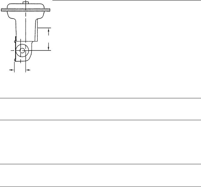
Figure 3. Center of Gravity Dimensions
125
(4.91)
mm 58.7 (INCH)
(2.31)
NOTE:
CENTER OF GRAVITY INCLUDES YOKE WEIGHT.
14B8083-A
Note
Find dimensions and center of gravity information in figures 3 and 4 and the approximate weight in table 1. This information is required for fabrication of the proper bracket and coupling.
1.Attach an appropriate mounting bracket (not provided) to the mounting plate (key 22) in the desired orientation with the cap screws (key 78). See figure 4 for mounting dimensions on the mounting plate. Tighten the cap screws to the value in table 2.
2.Consult figure 5 for available mounting styles and positions. The actuator is normally positioned vertically with the valve or other equipment in a horizontal pipeline.
Note
If the milled flats on the end of the actuator output shaft (key 87) are oriented so that the output shaft cannot accommodate the operated equipment shaft, refer to the Changing Positions procedure of the Changing Actuator Mounting section. This procedure describes how the output shaft can be repositioned to accommodate the operated equipment shaft.
3.Slide the actuator (with the user-provided mounting bracket attached) into the user-provided coupling on the operated shaft. Then, secure the actuator to the operated equipment in the desired mounting position with appropriate fasteners, such as mounting cap screws. See figure 4 for output shaft dimensions.
Principle of Operation
Refer to figure 6. The diaphragm rod (key 10) moves down as loading pressure is increased on top of the diaphragm (key 3). As the loading pressure is decreased, the spring (key 11) forces the diaphragm rod upward.
5
 Loading...