


Engine Description
2
2.1Model
2.2Engine Illustration
2.3Lube Oil Circuit Schematic
2.4Fuel System Schematic
9 |
9 Gerade |
7343en_k02_pdf |
9 |
05.10.1999, 9:20 Uhr |

|
|
Engine Description |
|
2.1 Model |
|
|
|
|
|
2 |
|
2.1.1 Rating Plate |
2.1.2 Rating Plate Location |
2.1.3 Engine Serial Number |
|
|
|
|
|
|
|
|
|
|
A |
B |
|
|
26 332 |
2 |
The model A, the engine serial number B and the performance data are stamped on the rating plate. The model and engine serial number must be given when ordering parts.
C |
|
|
|
* |
00022135 |
* |
|
|
|
26 421 |
1 |
The rating plate C is attached to the valve cover.
23045678 |
|
D |
|
26 422 |
0 |
The engine serial number B is stamped on the crankcase D as well as the rating plate.
10
7343en_k02_pdf |
10 |
05.10.1999, 9:21 Uhr |
2.1 Model |
|
Engine Description |
||
|
|
|
|
|
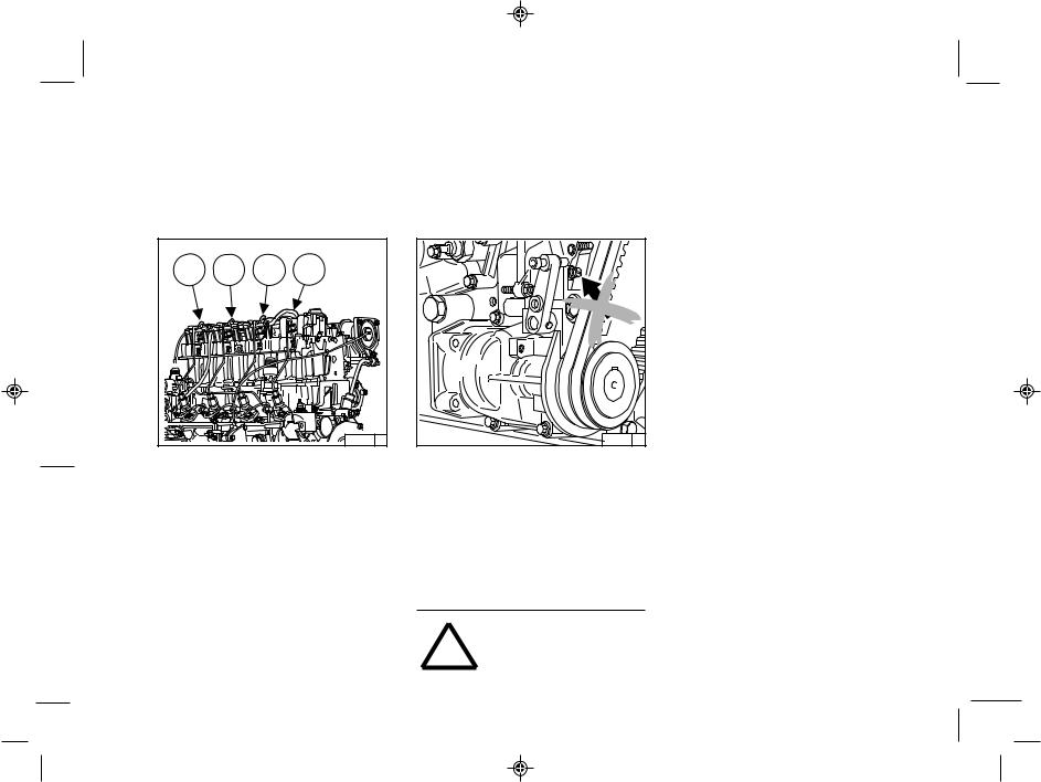
2.1.4 Cylinder Numbering |
2.1.5 Fuel Delivery Lock |
|
|
2 |
|
|
|
|
|
|
|
|
|
|
1 |
2 |
3 |
4 |
|
|
|
|
26 431 |
0 |
Cylinders are numbered consecutively, beginning at the flywheel end.
26 387 |
0 |
The manufacturer shall not be held liable for damages resulting from adjustments made to the regulator by the operator.
The lock screws are protected in order to prevent this:
1.with locking paint on model: torque balancer
2.with plastic protective cap on model: without torque balancer.
Adjustments to the regulator are to
!DEUTZ SERVICE - specialists.be carried out only by authorized
11 |
11 Gerade |
7343en_k02_pdf |
11 |
05.10.1999, 9:21 Uhr |

Engine Description 2.2 Engine Illustrations
2 |
2.2.1 Service Side |
|
FL 1011F |
||
|
|
|
|
|
|
|
|
|
1 |
Oil filler neck (valve-gear cover) |
|
|
|
|
|
|
|
|
2 |
Charge-air line / air-intake line |
21 |
|
|
|
|
|
1 |
3 |
Fan with integrated generator |
|
|
|
|
|
|
4 |
Narrow V-belt |
|||
|
|
|
|
|
|
|
|
5 |
Solenoid |
|
|
|
|
|
|
|
|
6 |
Toothed belt cover |
20 |
|
|
|
|
|
2 |
7 |
V-belt pulley on crankshaft |
|
|
|
|
|
|
8 |
Oil sump |
|||
|
|
|
|
|
|
|
|
9 |
Cut-out handle |
19 |
|
|
|
|
|
3 |
10 |
Speed control lever |
|
|
|
|
|
|
11 |
Oil dipstick |
|||
|
|
|
|
|
|
|
|
12 |
Crankshaft housing |
|
|
|
|
|
|
|
|
13 |
Oil fill point (on side of crankcase) |
18 |
|
|
|
|
|
4 |
14 |
Fuel pump |
|
|
|
|
|
|
15 |
Easy-change fuel filter |
|||
|
|
|
|
|
|
|
|
16 |
Connecting facility for oil heater |
17 |
|
|
|
|
|
5 |
17 |
Lube oil easy-change filter |
|
|
|
|
|
|
18 |
Removable coolant intake hood |
|||
|
|
|
|
|
|
|
|
19 |
Injection pumps |
|
|
|
|
|
|
|
|
20 |
Date plate |
16 |
|
|
|
|
|
6 |
21 |
Oil cooler |
|
|
|
|
|
|
|
|
|||
|
|
|
|
|
|
|
|
|
|
15 |
|
|
|
|
|
7 |
|
|
|
|
|
|
|
|
|
|
|
|
|
14 |
|
|
|
|
|
|
|
|
|
13 |
12 |
11 |
10 |
9 |
8 |
26 452 |
0 |
|
|
12 |
|
|
|
|
|
|
|
|
|
7343en_k02_pdf |
12 |
|
|
|
|
|
|
05.10.1999, 9:21 Uhr |
|
 Loading...