


COOKER HOOD - User instructions
 ODSAVAČ PAR - návod k použití
EMHÆTTE - Brugervejledning
 LIESITUULETIN – Käyttöohje
 ΑΠ ΡΡ ΦΗΤΗΡΑΣ ΣΕ ΕΚ∆ ΣΗ ΑΠ ΡΡ ΦΗΣΗΣ – Εγ ειρίδι ρήσης
 ELSZÍVÓ KÜRTŐ – Használati utasítás
AVTREKKSKAPPE – Bruksanvisning
 OKAP ZASYSAJĄCY - instrukcja obsługi
 HOTĂ ASPIRANTĂ – Manual de utilizare
 ВЫТЯЖНОЙ КОЛПАК - Руководство пользователя
SPISKÅPA – Bruksanvisning
|
|
|
|
|
|
||
Fig.1 |
|
|
|
|
|
|
|
|
|
|
|
|
|
|
|
Fig.2 |
|
Fig.3 |
|
|
|
||
|
|
|
|

Fig.4 |
Fig.5 |
- 3 -
|
|
|
Fig.6 |
|
|
|
|
Fig.7 |
|
|
Fig.9A |
|
|
|
|
|
|
|
|
|
Fig.8 |
|
|
|
|
|
Fig.9B |
|
Fig.9C |
|
||
|
|
|
|
|
|
|
|
- 4 - |

|
|
|
Fig.11A |
|
|
|
|
|
|
Fig.11B |
Fig.11C |
|
|
|
|
|
|
Fig.11D |
Fig.11E |
|
|
|
|
|
|
|
|
|
- 5 - |
|
Fig.12 |
Fig.14 |
|
|
Fig.13 |
Fig.15 |
Fig.16 |
Fig.17 |
|
|
- 6 -
ENGLISH GB
GENERAL
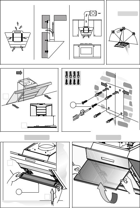
Carefully read the following important information regarding installation safety and maintenance. Keep this information booklet accessible for further consultations. The appliance has been designed for use in the ducting version (air exhaust to the outside – Fig.1B), filtering version (air circulation on the inside – Fig.1A) or with external motor (Fig.1C).
SAFETY PRECAUTION
1. Take care when the cooker hood is operating simultaneously with an open fireplace or burner that depend on the air in the environment and are supplied by other than electrical energy, as the cooker hood removes the air from the environment which a burner or fireplace need for combustion. The negative pressure in the environment must not exceed 4Pa (4x10⁻⁵ bar). Provide adequate ventilation in the environment for a safe operation of the cooker hood. Follow the local laws applicable for external air evacuation.
Before connecting the model to the electricity network:
-Control the data plate (positioned inside the appliance) to ascertain that the voltage and power correspond to the network and the socket is suitable. If in doubt ask a qualified electrician.
-If the power supply cable is damaged, it must be replaced with another cable or a special assembly, which may be obtained direct from the manufacturer or from theTechnical Assistance Centre.
2.WARNING !
In certain circumstances electrical appliances may be a danger hazard.
A)Do not check the status of the filters while the cooker hood is operating
B)Do not touch bulbs or adjacent areas, during or straight after prolonged use of the lighting installation.
C)Flambè cooking is prohibited underneath the cooker hood
D)Avoid free flame, as it is damaging for the filters and a fire hazard
E)Constantly check food frying to avoid that the overheated oil may become a fire hazard
F)Disconnect the electrical plug prior to any maintenance.
G)This appliance is not intended for use by young children or infirm persons without supervision
H)Young children should be supervised to ensure they do not play with the appliance
I)There shall be adequate ventilation of the room when the rangehood is used at the same time as appliances burning gas or other fuels
L)There is a risk of fire if cleaning is not carried out
in accordance with the instructions
This appliance conforms to the European Directive EC/2002/96, Waste Electrical and Electronic Equipment (WEEE).By making sure that this appliance is disposed of in a suitable manner, the user is helping to prevent potential damage to the environment or to public health.
The  symbol on the product or on the accompanying paperwork indicates that the appliance should not be treated as domestic waste, but should be delivered to a suitable electric and electronic appliance recycling collection point. Follow local guidelines when disposing of waste. For more information on the treatment, re-use and recycling of this product, please contact your local authority, domestic waste collection service or the shop where the appliance was purchased.
INSTALLATION INSTRUCTIONS
Assembly and electrical connections must be carried out by specialised personnel.
• Electric Connection
The appliance has been manufactured as a class II, therefore no earth cable is necessary.
The connection to the mains is carried out as follows: BROWN = L line
BLUE = N neutral
If not provided, connect a plug for the electrical load indicated on the description label. Where a plug is provided, the cooker hood must be installed in order that the plug is easily accessible.
An omnipolar switch with a minimum opening of 3mm between contacts, in line with the electrical load and local standards, must be placed between the appliance and the network in the case of direct connection to the electrical network.
•The distance between the supporting surface of the cooking appliance on which the cooking recipients are placed and the lower part of the kitchen hood must be a minimum of 45 cm, whether it is an electric hob, a gas hob or an induction hob.
If a connection tube composed of two parts is used, the upper part must be placed outside the lower part. Do not connect the cooker hood exhaust to the same conductor used to circulate hot air or for evacuating fumes from other appliances generated by other than an electrical source.
•In the case of assembly of the appliance in the suction version prepare the hole for evacuation of the air.
•We recommend the use of an air exhaust pipe with a diameter of 150. If a pipe with a smaller diameter is used, the efficiency of the product may be reduced and its operation may become noisier.
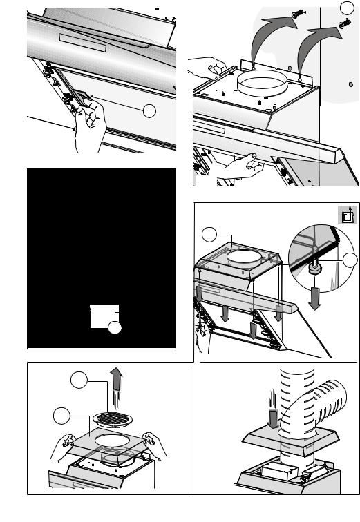
•Before starting to fix the hood, disconnect the anti-grease filter B (Fig.6) for easier appliance handling.
- 7 -

Before this operation, perform the following steps depending on the model purchased:
MODEL 1
Remove the 3 panels A as shown in Fig.4. Pull handle B as shown in Fig.6.
MODEL 2
Open panel C as shown in Fig.5. Pull handle B as shown in Fig.6.
If the appliance has a lid, remove it by removing the 4 screws B as shown in Fig.9A.
• WALL FIXING
Mark the position of the lower side of the hood on the wall (Fig.2A).Maintain the minimum distance required from the hob as shown in Fig.2B.
-Position the fixing template on the wall, making sure that the line coincides with the line previously made on the wall.
-Mark the fixing holes and cut them into the material (Fig.3).
-Fix the 2 top screws K and screw anchors (Fig.3), without tightening them completely.
-Place the appliance against the wall, align it in horizontal position and tighten screws K (Fig.7).
-Once the adjustment has been completed, fix the hood using the 2 screws C (Fig.8).
-When carrying out the fixing operations, use only screws and screw anchors suited to the type of wall (e.g.reinforced concrete, plasterboard etc.).
-If the screws and screw anchors are supplied with the appliance, make sure that they are suited to the type of wall to which the hood must be fixed.
•INSTALLATIONOFMODELSWITHOUTDECORATIVE DUCTS
EXTRACTOR HOOD
- Remove the 4 screws B as shown in (Fig.9A).
- Remove both grid E on the air outlet hole and lid M as shown in (Fig.9B).
- Connect the hood to the flexible hose (not supplied) and the hose to the air exhaust hole previously prepared (Fig.9C).
- Fix the lid once again by using the 4 screws previously removed in (Fig.9A).
•OPTIONAL ACCESSORIES
This model may have decorative ducts as optional accessories - ask your retailer for information.
Before fixing the decorative ducts, remove both the 4 screws B and lid M, as shown in (Fig.10A-B).
A sound-absorbing kit is also available (to be ordered as an OPTIONAL accessory) in order to increase the quietness level of the hood. The sound-absorbing layer must be applied to the back of the decorative panel. For fixing operations, refer to the instructions supplied with the kit.
• INSTALLATION OF MODELS WITH DECORATIVE DUCTS
Make sure the electrical power supply is within the measurements of the decorative connector.
Adjust the width of the support bracket of the top connector
(Fig.11C).Then fix it to the ceiling so that it is on the same axis as the hood using screws A (Fig.11C) adhering to the distance from the ceiling shown in (Fig.11B).Connect flange C to the air exhaust hole using flexible hose L (Fig.11D).
Slide the top duct into the bottom duct.Fix the bottom duct to the hood using screws B (supplied) (Fig.11E).
Pull out the top duct as far as the bracket and fix it using screws F (Fig.11C).
• FILTER HOOD Please note:
The filters should be ordered as accessories from your retailer.
We offer 2 different types of kit which can be used to transform the EXTRACTOR hood into a FILTER hood, in accordance with the type of appliance model purchased. One kit contains extractable filters (fig. 10) and the other contains circular filters (fig. 15).
1- If you find a bracket (such as the one indicated in fig. 14) included in the product packaging, this should be fixed to the hood using the 6 screws supplied.
To replace the active carbon filters pull lever B outwards as shown in (Fig.10).
2- If your product is not supplied with a bracket, this means that the active carbon filter is a circular version (fig. 15). The filters should be fitted to the extraction assembly inside the hood, by centring them and rotating them 90 degrees, until they click into place (Fig. 15).
USE AND MAINTENANCE
•It is recommended to operate the appliance prior to cooking.
It is recommended to leave the appliance in operation for 15 minutes after cooking is terminated in order to completely eliminate cooking vapours and odours.
The proper function of the cooker hood is conditioned by the regularity of the maintenance operations, in particular, the active carbon filter.
•The anti-grease filters capture the grease particles suspended in the air, and are therefore subject to clogging according to the frequency of the use of the appliance.
In order to prevent fire hazard, it is recommendable to clean the filter at a maximum of 2 months by carrying out the following instructions:
- Remove the filters from the cooker hood and wash them in a solution of water and neutral liquid detergent, leaving to soak.
- Rinse thoroughly with warm water and leave to dry. - The filters may also be washed in the dishwasher.
The aluminium panels may alter in colour after several washes. This is not cause for customer complaint nor replacement of panels.
•The active carbon filters purify the air that is replaced in the environment. The filters are not washable nor re-useable and must be replaced at maximum every four months. The saturation of the active carbon filter depends on the frequency of use of the appliance, by the type of cooking and the regularity of cleaning the anti-grease filters.
- 8 -
•Clean the fan and other surfaces of the cooker hood regularly using a cloth moistened with denatured alcohol or non abrasive liquid detergent.
•The illumination installation is designed for use during cooking and not for prolonged general illumination of the environment.Prolonged use of the illumination installation notably reduces the duration of the bulb.
Please note:
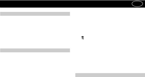
If your appliance model is fitted with side panels (A), for more thorough cleaning these can be removed by pulling them in the direction indicated in fig. 12.
• Replacing halogen light bulbs (Fig. 13).
To replace the halogen light bulbs B, remove the glass panel C using a lever action on the relevant cracks. Replace the bulbs with new ones of the same type.
Caution: do not touch the light bulb with bare hands.
COMMANDS: (Fig.17) Push-button A = on/off lights switch
Push-button B = on/off cooker hood switch. The appliance switches on at speed level 1, If the cooker hood is on depress the push-button for 2 sec. to switch off the cooker hood. If the cooker hood is at speed level 1 it will not be necessary to depress the push-button to switch the cooker hood off. Decreases the motor speed.
Display C = indicates the motor speed level selected and activates the timer.
Push-button D = switches on the cooker hood. Increases the motor speed. Touching the key at 3rd speed, the intensive function runs for 10’, then the appliance go back to work at the original speed. During this function the display blinks.
Key E = The Timer times the functions on activation for 15 minutes, after which they are switched off. The Timer is deactivated by re-pressing Key E. When the Timer is activated the decimal point must flash on the display. The Timer cannot be activated if the intensive speed is functioning.
The “clean air” function is activated by pressing key E for 2 seconds when the appliance is switched off.
This switches the motor on for 10 minutes every hour at the first speed.
During functioning a rotary movement of the peripheral segments must be visualised on the display.When this time has passed the motor switches off and the fixed letter “C” must be visualised on the display until the motor re-starts after 50 minutes for another 10 minutes and so on.
Press any key apart from the light keys to return to normal functioning. Press key E to deactivate the function.
• Active carbon/grease filter saturation:
-When display item C flashes, at a speed where it alternates with the letter F (e.g.1 and F), the grease filters must be washed.
-When display item C flashes, at a speed where it alternates with the letter A (e.g.1 and A), the carbon filters must be replaced.
After the clean filter has been positioned correctly, the electronic memory must be reset by pressing button A for approximately 5 seconds, until the indication F or A
shown on the display C stops flashing.
•COMMANDS: (Fig.16) LUMINOUS the key symbols are explained below:
A = LIGHT B = OFF
C = SPEED I D = SPEED II E = SPEED III
F = AUTOMATIC STOP TIMER - 15 minutes (*)
•If your appliance does not have the INTENSIVE speed function, press key E for two seconds and it will be activated for 10 minutes after which it will return to the previously set speed.
When the function is active the LED flashes.To interrupt it before the 10 minutes have expired press key E again.
•By pressing key F for two seconds (with the hood switched off) the “clean air” function is activated. This function switches the appliance on for ten minutes every hour at the first speed.As soon as this function is activated the motor starts up at the first speed for ten minutes, During this time key F and key C must flash at the same time.
After ten minutes the motor switches off and the LED of key F remains switched on with a fixed light until the motor starts up again at the first speed after fifty minutes and keys F and C start to flash again for ten minutes and so on.
By pressing any key for the exclusion of the hood light the hood will return immediately to its normal functioning (e.g. if key D is pressed the “clean air” function is deactivated and the motor moves to the 2nd speed straight away. By pressing key B the function is deactivated).
(*) The “automatic stop timer” delays stopping of the hood, which will continue functioning for 15 minutes at the operating speed set at the time this function is activated.
• Active carbon/grease filter saturation:
-When button A flashes at a frequency of 2 seconds, the grease filters must be cleaned.
-When button A flashes at a frequency of 0.5 seconds, the carbon filters must be replaced.
After the clean filter has been replaced, the electronic memory must be reset by pressing button A for approximately 5 seconds, until the light on the button stops flashing.
THE MANUFACTURER DECLINES ALL RESPONSIBILITY FOR EVENTUAL DAMAGES CAUSED BY BREACHING THE ABOVE WARNINGS.
- 9 -
ČESKYPOLSC |
CZ |
||
ÚVOD’ |
negativním následkům na životní prostředí a na zdraví. |
||
Přečtěte si pozorně obsah návodu, protože poskytuje |
Symbol |
na výrobku nebo na přiložené dokumentaci |
|
poukazuje na to, že se s tímto výrobkem nesmí zacházet |
|||
důležité informace týkající se bezpečné instalace, |
|||
jako s běžným domovním odpadem, ale musí se odeslat |
|||
používání i údržby zařízení. Uchovejte si návod pro |
|||
do vhodné sběrny určené pro recyklaci elektrických |
|||
jakoukoliv budoucí potřebu. |
|||
a elektronických zařízení. Zařízení se musíte zbavit |
|||
Přístrojjeurčenkodsávání(odváděnívzduchuven–obr.1B), |
|||
v souladu s místními předpisy pro likvidaci odpadu. |
|||
filtrování (recyklace vzduchu v místnosti – obr.1A) nebo |
|||
Podrobnější informace o zacházení s tímto výrobkem, |
|||
k použití s externě umístěným motorem (obr.1C). |
|||
jeho opětovným použitím a recyklací můžete získat, když |
|||
|
|||
|
se obrátíte na příslušný místní úřad, sběrnou službu |
||
BEZPECNOSTNÍ OPATRENÍ |
domovního odpadu nebo obchod, ve kterém jste výrobek |
||
|
zakoupili. |
|
|
1.Vyžaduje se opatrnost, jestliže jsou současně v činnosti |
NÁVOD K INSTALACI |
||
odsávač par a jiný hořák nebo tepelné zařízení závisející |
|
|
|
na vzduchu místnosti a napájené jinou energií než |
Operace spojené s montáží a elektrická napojení musí |
||
elektrickou, protože odsávač par spotřebovává vzduch |
|||
být provedeny pouze odborným personálem. |
|||
z okolí, který hořák nebo jiné tepelné zařízení potřebují |
|||
|
|
||
ke spalování. Negativní tlak nesmí překročit 4Pa (4x10⁻⁵ |
• Elektrické zapojení |
||
bar). K bezpečnému provozu je tedy nutná odpovídající |
|||
Zařízení je vyrobeno v II.třídě, a proto žádný vodič nesmí |
|||
ventilace místnosti. Při odvádění vzduchu do vnějšího |
|||
být uzemněn. |
|||
prostředí je nutné se řídit platnými předpisy Vaší země. |
|||
Napojení k elektrické síti musí být provedeno |
|||
|
|||
Před napojením modelu na elektrickou síť: |
následovně: |
||
HNĚDÁ = |
L vodič |
||
- Zkontrolujte tabulku s údaji umístěnou uvnitř přístroje a |
|||
MODRÁ = |
N neutrální vodič |
||
ověřte si, že napětí a výkon odpovídají místní síti a rovněž |
|||
Na přívodní kabel, pokud ji již neobsahuje, namontujte |
|||
zásuvka je vhodná. |
|||
zástrčku normalizovanou pro příkon uvedený v technických |
|||
V případě jakékoliv pochyby se poraďte s kvalifikovaným |
|||
charakteristikách výrobku. |
|||
elektrikářem. |
|||
V případě přímého zapojení na elektrickou síť je nezbytné |
|||
|
|||
- Je-li napájecí kabel poškozen, musí být nahrazen |
přístroj připojit přes vícepólový spínač s minimální |
||
vzdáleností 3 mm mezi rozpojenými kontakty, dostatečně |
|||
speciálním kabelem nebo sadou, které jsou k dispozici u |
|||
dimenzovaný a odpovídající platným normám. |
|||
výrobce nebo v jeho servisním středisku. |
|||
|
|
||
2. UPOZORNĚNÍ !
Za určitých okolností mohou být elektrické spotřebiče nebezpečné.
A)Neprovádějte kontrolu filtrů se zapnutým spotřebičem
B)Nedotýkejte se žárovek a prostoru kolem nich behem užití nebo ihned po dlouhodobém užití osvetlovacího zarízení.
C)Nedotýkejte se žárovek, bylo-li zařízení déle v chodu
D)Je zakázáno upravovat pokrmy manipulí přímého ohně pod fungujícím odsávačem
E)Vyvarujte se volnému plameni,je škodlivý pro filtry a mohl by způsobit požár
F)Při smažení jídel zajistěte, aby se rozpálený olej nevznítil
G)Zařízení nebylo navrženo pro použití dětmi nebo nesvéprávnými osobami bez dozoru.
H)Zkontrolujte, zda si děti nehrají se zařízením.
I)Před provedením jakékoliv údržby vypněte přístroj z elektrické sítě.
Toto zařízení je označeno v souladu s Evropskou směrnicí 2002/96/ES, Waste Electrical and Electronic Equipment (WEEE). Tím, že se uživatel ujistí o správné likvidaci tohoto výrobku, přispívá k předcházení případným
•Minimální vzdálenost povrchu, na který se kladou nádoby na vaření a který se nachází na zařízení používaném k vaření, od nejnižší části odsavače u varné desky s elektrickým, plynovým nebo indukčním ohřevem musí být nejméně 45 cm.
Vývod odsavače nesmí být napojen na vývod, ve kterém cirkuluje teplý vzduch, nebo který je používán k odvádění kouře ze zařízení napájených jinou energií než elektrickou.
•V případě montáže přístroje ve verzi odsávače je třeba připravit otvor k evakuaci vzduchu.
•Doporučuje se použití kouřové trubky s průměrem 150. Použití redukce by mohlo negativně ovlivnit vlastnosti výrobku a zvýšit hlučnost
•Před zahájením montáže vyjměte z odsavače protitukový filtr B (obr. 6). Usnadníte si tak manipulaci se zařízením. Před provedením této operace proveďte následující fáze na základě modelu, který vlastníte:
MODEL 1
Sejměte 3 panely A způsobem naznačeným na obr. 4. Potáhněte za rukojeť B způsobem naznačeným na obr. 6.
- 10 -
MODEL 2
Otevřete panel C způsobem naznačeným na obr. 5. Potáhněte za rukojeť B způsobem naznačeným na obr. 6.
Když je zařízení dodáno s krytem, odmontujte jej odšroubováním 4 šroubů B způsobem naznačeným na obrázku 9 A.
• UPEVNĚNÍ NA STĚNU
Vyznačte na stěně úroveň spodního okraje odsavače v souladu s obr.2A (mějte na paměti minimální vzdálenost od varné desky - obr.2B).
-Umístěte upevňovací šablonu na stěnu a dbejte přitom, aby se příslušná čára shodovala s čárou naznačenou v předcházejícím odstavci.
-Vyznačte a připravte montážní otvory (obr. 3).
-Upevněte 2 horní šrouby K, aniž byste je zcela zašroubovali; upevněte i rozpěrné kotvy (obr. 3).
-Umístěte zařízení na stěnu, vyrovnejte jej do vodorovné polohy a zašroubujte šrouby K (obr. 7).
-Po ukončení nastavování polohy proveďte konečné připevnění odsavače prostřednictvím 2 šroubů C (obr. 8).
-Při různých montážích používejte šrouby a rozpěrné kotvy vhodné pro daný druh stěny (např. z betonu, sádrokartonu atd.)
-V případě, že se šrouby a kotvy dodávají v příslušenství výrobku, se ujistěte, zda jsou vhodné pro daný druh stěny, ke které má být připevněn odsavač.
•INSTALACE MODELŮ BEZ ESTETICKÝCH KOMÍNŮ SACÍ VERZE
- Odmontujte 4 šrouby B způsobem naznačeným na (obr. 9 A).
- Odložte mřížku E, umístěnou nad otvorem pro výstup vzduchu, i kryt M, a to způsobem naznačeným na (obr. 9 B).
- Připojte odsavač k hadici (nedodává se), jejíž druhý konec bude připojen k předem připravenému otvoru na odvádění vzduchu (obr. 9 C).
- Znovu upevněte kryt 4 šrouby s použitím šroubů, které jste předtím odmontovali (obr. 9 A).
•VOLITELNÉ PŘÍSLUŠENSTVÍ
Tento model odsavače může být v rámci volitelného příslušenství vybaven estetickými komíny, o které je třeba požádat vašeho prodejce.
Před instalací estetických komínů je třeba odmontovat 4 šrouby B a kryt M způsobem naznačeným na (obr. 10 A - B).
Dále je k dispozici fonoabsorpční sada (kterou je třeba objednat v rámci VOLITELNÉHO PŘÍSLUŠENSTVÍ), umožňující snížit hlučnost odsavače. Tato fonoabsropční vrstva se aplikuje na estetický panel. Při montáži je třeba postupovat dle pokynů, které jsou součástí uvedené sady.
• INSTALACE MODELŮ S ESTETICKÝMI KOMÍNY
Přiveďte elektrické napájení do prostoru dekorativního spoje.
Seřiďte šířku opěrného třmene horního spoje (Obr.11 C). Poté jej upevněte na strop tak, aby se nacházel v jedné ose s vaším odsavačem; upevnění proveďte prostřednictvím
šroubů A (Obr.11 C) a za dodržení vzdálenosti od stropu, která je uvedena na (Obr. 11 B). Prostřednictvím hadice L připojte přírubu C k otvoru pro odvádění vzduchu (Obr. 11 D).
Zasuňte horní komín dovnitř spodního komínu. Upevněte spodníkomínkodsavačispoužitímšroubůBzpříslušenství (Obr. 11 E).
Vyvlečte horní komín až po třmen a upevněte jej prostřednictvím šroubů F (Obr. 11 C).
• FILTRAČNÍ VERZE Upozornění!
Uhlíkové filtry se musí objednat u vašeho prodejce jako příslušenství.
Pro změnu odsavače z ODSÁVACÍ verze na FILTRAČNÍ verzi máme na základě modelu, který vlastníte, k dispozici 2 druhy odlišných sad, jednu s kazetovými filtry (obr. 10) a druhou s kruhovými filtry (obr. 15).
1- Když v balení najdete třmen jako ten, který je znázorněn na obr. 14, je třeba jej upevnit k odsavači prostřednictvím 6 šroubů z příslušenství.
Při výměně filtrů s aktivním uhlím je třeba potáhnout směrem ven páku B, a to způsobem naznačeným na (obr. 10).
2- Když v obalu vašeho výrobku není dodán třmen, znamená to, že filtr s aktivním uhlím je kruhový (obr. 15). Filtry musí být aplikovány na odsávací jednotku uvnitř odsavače a je třeba je vystředit vůči samotnému odsavači a otočit o 90 stupňů až do zacvaknutí (obr. 15).
POUŽITÍ A ÚDRŽBA
•Doporučujeme uvést zařízení do činnosti ještě před zahájením přípravy jakéhokoli jídla. Doporučujeme ponechat zařízení v činnosti také na dobu 15 minut po ukončení přípravy jídel, aby byl zcela odveden zapáchající vzduch.
Správná činnost odsavače je podmíněna správnou a nepřetržitou údržbou; zvláštní pozornost je třeba věnovat protitukovému filtru a filtru s aktivním uhlím.
•Protitukový filtr má za úkol zachycovat mastné částice nacházející se ve vzduchu, proto je v průběhu proměnné doby vystaven ucpávání; tato doba závisí na používání zařízení.
Akrylový filtr, který je uložen na mřížce, je třeba vyměnit, když dojde ke změně barvy nápisů viditelných přes mřížku a k expanzi použitého inkoustu; nový filtr musí být aplikován tak, aby byly nápisy viditelné přes mřížku z vnější části odsavače.
V případě, že akrylové filtry nejsou vybaveny nápisy, nebo v případě, že jsou přítomné kovové filtry nebo filtry s hliníkovým panelem, je třeba tyto filtry umýt podle následujících pokynů maximálně každé 2 měsíce:
- Vyjměte filtr z mřížky a umyjte jej roztokem vody a tekutého neutrálního čisticího prostředku a nechte odmočit špínu.
- Opláchněte jej dostatečným množstvím vlažné vody a nechte uschnout.
Kovové filtry a/nebo hliníkový panel se mohou umývat i v myčce nádobí. Po několika umytích může u hliníkových filtrů nebo panelů dojít ke změně barvy. Tato skutečnost neumožňuje podání reklamace za účelem jejich výměny. V případě nedodržení pokynů pro výměnu a mytí
- 11 -
protitukových filtrů se může vyskytnout riziko jejich zapálení.
•Filtry s aktivním uhlím slouží k čištění vzduchu, který se znovu vhání do okolního prostředí. Filtry se nesmí mýt ani regenerovat a musí se měnit maximálně každé čtyři měsíce. Nasycení aktivního uhlí závisí na krátkodobém nebo déletrvajícím používání zařízení, na druhu sporáku a pravidelnosti, se kterou se provádí vyčištění protitukového filtru.
•Pravidelně vyčistěte všechny nánosy na ventilátoru a na dalších plochách s použitím navlhčeného hadru a denaturovaného lihu nebo tekutých neutrálních neabrazivních čisticích prostředků.
•Osvětlení je navrženo pro použití během vaření a ne pro dlouhodobější použití za účelem osvětlení okolního prostředí.Dlouhodobější použití osvětlení výrazně snižuje průměrnou životnost žárovek.
Upozornění!
Když je váš model vybaven bočními panely (A), je možné provést důkladnější vyčištění jejich vytažením ve směru naznačeném na obr. 12.
• Výměna halogenových žárovek (obr. 13).
Při výměně halogenových žárovek B sejměte sklíčko C po jeho nadzvednutí v místě příslušných otvorů.Žárovky nahraďte novými žárovkami stejného druhu.
Upozornění:Nedotýkejte se žárovky holýma rukama.
OVLÁDÁNÍ (Obr. 17):
Tlačítko A – rozsvítí/zhasne světla
Tlačítko B – zapne/vypne odsávač. Přístroj je uveden do chodu při první rychlosti.Je-li odsavač zapnutý, vypněte jej stisknutím tlačítka na 2 sek.Pokud se odsávač nachází ve fázi první rychlosti, není nezbytné dlouze stisknout tlačítko za účelem vypnutí. Snižuje se rychlost motoru.
Displej C – ukazuje zvolenou rychlost motoru a uvedení do chodu časového spínače
Tlačítko D – zapne odsávač. Zvyšuje rychlost motoru. Stiskne-li se tlačítko od třetí rychlosti, je nastavena intenzívní funkce na 10 vteřin, pak se přístroj vrátí do fáze pracovní rychlosti v okamžiku uvedení do chodu. Během této funkce displej bliká.
Tlačítko E = Časovač slouží k časovému ovládání funkcí v průběhu 15 minut po jeho aktivaci; po uplynutí uvedené doby se tyto funkce vypnou.Vypnutí časovače se provádí stisknutím tlačítka E. Aktivace funkce časovače musí být signalizována blikáním desetinné tečky na displeji. Je-li aktivována intenzivní rychlost, aktivace časovače není možná.
Stisknutím tlačítka E na 2 sekundy při vypnutém zařízení se aktivuje funkce „clean air“. V rámci této funkce se motor zapne každou hodinu na 10 minut a během této doby se bude otáčet první rychlostí. Během jeho činnosti bude na displeji zobrazen rotační pohyb obvodových segmentů. Po uplynutí uvedené doby dojde k vypnutí motoru a na displeji musí být zobrazeno písmeno „C“, aniž by blikalo, dokud nebude po uplynutí dalších 50 minut motor znovu spuštěn na 10 minut, a tak dále.
• Nasycení protitukových filtrů/filtrů s aktivním uhlím: Fig.11
- Když displej C bliká a střídavě zobrazuje provozní
rychlost a písmeno F (např.1 a F), je třeba vyčistit protitukové filtry.
- Když displej C bliká a střídavě zobrazuje provozní rychlost a písmeno A (např.1 a A), je třeba vyměnit uhlíkové filtry.
Po vložení čistého filtru je třeba vynulovat elektronickou paměť stisknutím tlačítka A na dobu přibližně 5 sek., dokud signalizace F nebo A na displeji C nepřestane blikat.
OVLÁDÁNÍ: (Obr.16 SVĚTELNÉ následuje přehled symbolů:
Tlačítko A – OSVĚTLENÍ
Tlačítko B – VYPNUTÍ
Tlačítko C – PRVNÍ RYCHLOST
Tlačítko D – DRUHÁ RYCHLOST
Tlačítko E – TŘETÍ RYCHLOST
Tlačítko F – ČASOVÝ SPÍNAČ AUTOMATICKÉVYPNUTÍ 15 minut (*)
Pokud je váš prístroj vybven funkcí INTENZÍVNÍ rychlost, je treba stisknout po dobu aespon 2 s tlacítko E a rychlost bude aktivována po deset minut a poté se vrátí do rychlosti, jež byla předem nastavena.
Pokud je funkce aktivní, led bliká.Chcete –li ji přerušit před vypršením 10 minut, stiskněte znovu klávesu E.
Po stisknutí tlacítka F po dobu 2 s (kryt je vypnut) bude aktivována funkce „clean air“. Tato funkce zapne motor na deset minut každou hodinuna první rychlost. Jakmile bude tato funkce aktivována, motor bude uveden do chodu na první rychlost po dobu 10 s, behem které budou blikat soucasne tlacítka F a C. Po uplynutí této doby se motor vypne a led tlacítka F zustane osvetlen až do doby, kdy po 50 minutách bude znovu motor uveden do chodu na první rychlost a led F a C znovu zacnou blikat po 10 minut a tak dále. Po stisknutí jakéhokoliv tlacítka s výjimkou svetel se kryt okamžite vrátí do svého normálního fungování.(napr. pokud se stiskne tlacítko D, deaktivuje se funkce „clean air“ a motor zacne pracovat na druhou rychlost, stisknutím tlacítka B se tato funkce deaktivuje.
(*) Funkce „ČASOVÝ SPÍNAČ AUTOMATICKÉVYPNUTÍ“ opožďuje vypnutí odsávače, který bude pokračovat ve funkci pracovní rychlostí, která byla nastavena v okamžiku zapnutí této funkce, 15 minut.
výrobce odmítá jakoukoliv zodpovědnost zaškodyzpůsobenénedodrženímuvedených upozornění.
- 12 -
DANSK DK
GENERELLE OPLYSNINGER
Læs omhyggeligt indholdet af denne brugsanvisning, da den giver vigtige oplysninger vedrørende sikkerheden ved installering, brug og vedligeholdelse. Opbevar brugsanvisningen til senere brug.Apparatet er udarbejdet til at kunne fungere; udsugende (udledning af luft til eksterne omgivelser Fig.1B) filtrerende (intern cirkulation af luft Fig.1A) og med udvendig motor. (Fig.1C).
OPLYSNINGER VEDRØRENDE SIKKERHED
1. Udvis forsigtighed hvis der samtidigt med emhætten er en varmekilde eller flamme i funktion, som er afhængig af luften i omgivelserne og forsynet med energi, der ikke er elektrisk, eftersom emhætten fjerner den luft fra omgivelserne, som flammen eller varmekilden har brug for til forbrænding.Det negative tryk i lokalet må ikke overstige 4 Pa (4x10⁻⁵ bar). For størst mulig sikkerhed, sørg for en passende ventilation af rummet.Hvad angår udsugningen til eksterne omgivelser følg de gældende normer.
Før modellen tilsluttes el-nettet:
-Kontrollèr informationsetiketten (placeret indeni apparatet), for at sikre, at spændingen og styrken er i overensstemmelse med el-nettet og at stikkontakterne er egnede. Hvis De er i tvivl, konsultèr en kvalificeret elektriker.
-Hvis forsyningsledningen er beskadiget, skal den udskiftes med en ledning eller en særlig samling fra fabrikanten eller et autoriseret servicecenter.
2. ADVARSEL!
I bestemte situationer kan elektriske hvidevarer være farlige.
A)Forsøg ikke at kontrollere filtrene mens emhætten er tændt.
B)Rør ikke ved pærer eller områderne omkring dem i forbindelse med længere brug af belysningsanlægget eller straks herefter.
C)Rør ikke ved lamperne efter længerevarende brug af apparatet.
D)Det er forbudt at flambere under emhætten.
E)Undgå åben flamme da det er skadelig for filtrene og kan forårsage brand.
F)Hold friturestegning under konstant overvågning for at undgå, at olien overophedes og bryder i brand.
G)Apparatet må aldrig bruges af børn eller af personer, der ikke har de mentale eller fysiske egenskaber til korrekt brug, uden overvågning.
H)Hold øje med, at børn ikke leger med apparatet.
I)Før man udføre enhver form for vedligeholdelse skal emhætten være afbrudt fra el-nettet.
Dette apparat er udviklet i overensstemmelse med det europæiske direktiv 2002/96/EF om affald
af elektrisk og elektronisk udstyr (WEEE). Ved at sikre sig, at dette produkt bortskaffes på korrekt vis, bidrager
brugeren til at forhindre eventuelle negative miljømæssige og sundhedsmæssige påvirkninger.
Symbolet  på produktet eller på dokumentationen, der følger med produktet, angiver, at produktet ikke skal behandles som husholdningsaffald, men at det skal bortskaffes på passende vis på genbrugsstationer til elektriske og elektroniske apparater. Apparatet skal bortskaffes i overensstemmelse med de gældende regler for bortskaffelse af affald. For yderligere oplysninger om håndtering, genvinding og genbrug af dette produkt, bedes man kontakte de lokale myndigheder, teknisk forvaltning eller forretningen, hvor produktet er købt.
INSTRUKTION VED INSTALLERING
Monteringenogudførelsenafdeelektriskeforbindelser, skal udføres af specialiseret personale.
Den elektriske forbindelse.
Apparatet er udarbejdet i klasse II, derfor skal der ikke tilsluttes et kabel til jordforbindelsen.
Tilslutning til el-nettet skal udføres som følgende: BRUN = L Linje
BLÅ = N Neutal
Hvis det ikke allerede findes, montèr da et standardstik beregnet til den forsyning, som er angivet på etiketten.Hvis der allerede er et stik, sørg da for at det er let tilgængelig efter installation af apparatet. I tilfælde af en direkte tilslutning til el-nettet er det nødvendigt at anbringe en flerpolet afbryder med en afstand mellem kontakterne på minimum 3 mm, mellem apparatet og nettet. Afbryderen skal passe til elforsyningen og være i overenstemmelse med de gældende normer.
•Minimumsafstanden mellem overfladen, hvor gryder og pander placeres på kogefladen og den nederste del af emhætten skal være mindst 45 cm, hvis det er et gaskomfur, et el-komfur eller et induktionskomfur.
Hvis der anvendes et forbindelsesrør bestående af to eller flere dele, skal den øverste del placeres udenpå den nederste.Tilslut ikke udledningen fra emhætten med et rør, hvori der cirkulere varm luft eller som anvendes til at udlede røg fra apparater, der ikke bruger elektrisk energi.
•I de tilfælde, hvor apparatet skal installeres i en udsugende version, forberedes åbningen til udledning af luft.
- Det anbefales at anvende en luftudsugningsslange med en diameter pĺ 150.
Hvis der anvendes en mindre slange, kan det forringe produktets ydelse og medfřre řget střj
• Inden emhætten monteres skal man afmontere fedtfilteret B (Fig.6), for bedre at kunne komme til.
Udfør først følgende trin, alt efter hvilken model, der er tale om:
MODEL 1
Fjern de 3 paneler A, som vist i fig.4.
- 13 -

Træk i håndtaget B, som vist i fig. 6.
MODEL 2
Åbn panelet C, som vist i fig.5. Træk i håndtaget B, som vist i fig. 6.
Hvis apparatet er udstyret med kuppel, skal den fjernes ved hjælp af de 4 skruer B, som vist i figur 9 A.
•VÆGMONTERING
Placér emhætten mod væggen, fig. 2A, og markér den nederste kant (vær opmærksom på minimumsafstanden til komfuret, fig. 2B).
-Placér skabelonen på væggen, og sørg for, at linjen passer med den, der blev afmærket i forrige trin.
-Markér og bor huller til montering (fig.3).
-Fastgør de 2 øverste skruer K, uden at skrue dem helt i, og rawlplugs (fig.3).
-Anbring emhætten mod væggen, tilret den vandret og spænd skruerne K (fig.7).
-Ret emhætten til, og skru den helt fast med de 2 skruer C (fig.8).
-Der skal anvendes skruer og rawlplugs, der passer til vægtypen (f.eks. armeret beton, gipsvæg osv.).
-Hvis der følger skruer og rawlplugs med, skal man først sikre sig, at de passer til den type væg, som emhætten skal monteres på.
•INSTALLATION AF MODELLER UDEN AFSKÆRMNING
EMHÆTTE MED UDSUGNING
- Løsn de 4 skruer B, som vist i (fig. 9 A).
- Fjern både risten E over udsugningshullet og kuplen M, som vist i (fig. 9 B).
- Tilslut emhætten til slangen (følger ikke med), som derefter skal tilsluttes udsugningsåbningen, som er klargjort (fig. 9 C).
- Spænd derefter kuplen fast med de 4 skruer, som blev løsnet i (fig. 9 A).
•OPTIONAL
Til denne emhættemodel fås afskærmning som ekstraudstyr på efterspørgsel hos forhandleren.
Inden afskærmningen monteres, skal man løsne de 4 skruer B og fjerne kuplen M, som vist i (fig.10 A - B).
Der fås også et støjdæmpersæt (skal bestilles som OPTIONAL), så emhætten bliver endnu mere støjsvag. Støjdæmperen skal installeres på bagsiden af afskærmningen. Se brugsanvisningen, der følger med sættet, for yderligere anvisninger.
• INSTALLATION AF MODELLER MED AFSKÆRMNING
Sørg for strømtilførsel inden i afskærmningens samling. Justér bredden på beslaget til den øverste del (Fig.11 C). Fastgør den herefter til loftet, så den er på linje med emhætten, ved hjælp af skruerne A (Fig.11 C), og vær opmærksom på afstanden til loftet, som angivet i (Fig.11 B).Tilslut flangen C til udsugningsåbningen (Fig.11 D) ved hjælp af en slange L.
Skub den øverste del af emhætten ned i den nederste del. Fastgør den nederste del af emhætten ved hjælp af skruerne B, der følger med (Fig.11 E).
Træk den øverste del af emhætten op til beslaget, og fastgør den ved hjælp af skruerne F (Fig.11 C).
• EMHÆTTE MED FILTER
Vær opmærksom!
Kulfiltrene skal bestilles hos forhandleren som ekstraudstyr.
For at ændre emhætten fra emhætte med UDSUGNING til emhætte med FILTER, alt efter den model man har, findes 2 forskellige sæt, ét med firkantede filtre (fig.10) og ét med runde filtre (fig.15).
1- Hvis emballagen indeholder et beslag, som vist i fig.14, skal dette fastgøres til emhætten med de 6 medfølgende skruer.
For at udskifte kulfiltrene skal man trække grebet B nedad, som vist i (fig. 10).
2- Hvis emballagen ikke indeholder beslaget, betyder det, at kulfiltret er rundt (fig.15).
Filtrene skal monteres på udsugningselementet i emhætten og skal drejes 90 grader, indtil de klikker på plads (fig. 15).
BRUG OG VEDLIGEHOLDELSE
•Det anbefales, at apparatet sættes i funktion, inden man begynder tilberedningen af madvarer. Det anbefales, at lade emhætten køre i 15 minutter efter endt tilberedning, så al mados suges ud.
Korrekt funktion af emhætten afhænger af en korrekt og jævnlig vedligeholdelse.Man skal især være opmærksom med at udskifte fedtfilteret og det aktive kulfilter.
•Fedtfilteret har til opgave at tilbageholde de fedtpartikler, der findes i luften. Filteret vil derfor blive tilstoppet med tiden, alt efter hvor ofte emhætten anvendes.
Akrylfilteret, der støtter på risten, skal udskiftes, når skriften på filteret, der er synlig gennem risten, skifter farve og blækket løber ud.Det nye filter skal monteres, så skriften er synlig gennem risten ude fra emhætten.
Hvis akrylfiltrene ikke har påtrykt skrift, eller hvis der anvendes metalfiltre eller filtre med aluminiumspanel, skal filtrene - for at forhindre brandfare - rengøres mindst hver 2. måned på følgende måde:
-Tag filteret ud af risten, og rengør det i neutralt sæbevand for at fjerne al snavs.
- Skyl efter med rigelige mængder lunken vand, og lad filteret tørre.
Metalfilter og/eller filtre med aluminiumspanel kan også vaskes op i opvaskemaskine. På aluminiumsfiltre eller filtre med aluminiumspanel kan der opstå misfarvninger efter nogle vask. Dette giver ikke ret til reklamation med henblik på udskiftning.
I tilfælde af manglende overholdelse af anvisningerne vedrørende udskiftning og rengøring, kan der opstå brandfare i fedtfiltrene.
•De aktive kulfiltre har til opgave at rense den luft, der sendes tilbage i lokalet. Filtrene kan ikke vaskes eller genbruges og skal udskiftes mindst hver fjerde måned. Mætningen af det aktive kul afhænger af, hvor ofte emhætten er i brug, komfurets type og hvor ofte fedtfilteret rengøres.
•Rengør ofte alle fedtaflejringer på ventilatoren og andre overflader med en klud opblødt i denatureret sprit eller et ikke-slibende og neutralt rengøringsmiddel.
- 14 -
 Loading...