


Data Sheet
Float valve
Type HFI
Robust and reliable solution for high pressure control
HFI is a high pressure float valve with internal liquid measuring device. The float valve is designed for direct flange mounting or welding on to plate heat exchanger type condensers, as illustrated in Figure 1: Plate heat exchanger
HFI is direct acting, therefore no differential pressure is required to activate the valve.
HFI is robust and reliable due to its simple design. The float valve is equipped with a purge valve for purging non condensable gases e.g. air from the top of the valve housing. This feature is also useful if the valve has to be serviced.
The HFI is available with two external connections on the housing for drainage and pressure equalizations.
AI220786430153en-001101

Float valve, type HFI
Features
•Designed for direct flange mounting on to plate heat exchanger type condensers
•Can be mounted directly on vessels
•Temperature range: -50 °C /+80 °C (-58 °F/+176 °F)
•Equipped with purge valve for purging non condensable gasses
•Available with external connections for drainage and pressure equalizations
•Maximum operating pressure is 25 bar (363 psig)
•Suitable for R717 (ammonia), HCFC and HFC with a density of 500 through 700 kg/m3 (31.21 - 43.70 lb/ft3). For densities outside this range please contact your local Danfoss sales company.
•Housing i.e. shell and flange are made of special steel approved for low temperature application
•Classi„cation: DNV, CRN, BV, EAC etc. To get an updated list of certi„cation on the products please contact your local Danfoss Sales Company.
Figure 1: Plate heat exchanger
© Danfoss | Climate Solutions | 2021.09 |
AI220786430153en-001101 | 2 |

Float valve, type HFI
Media
Refrigerants
Refrigerants
Suitable for R717 (ammonia), HCFC and HFC with a density of 500 through 700 kg/m3 (31.21 - 43.70 lb/ft3). For densities outside this range please contact your local Danfoss sales company.
Flammable hydrocarbons are not recommended. For further information please contact your local Danfoss Sales Company.
New refrigerants
Danfoss products are continually evaluated for use with new refrigerants depending on market requirements.
When a refrigerant is approved for use by Danfoss, it is added to the relevant portfolio, and the R number of the refrigerant (e.g. R513A) will be added to the technical data of the code number. Therefore, products for speci„c refrigerants are best checked at store.danfoss.com/en/, or by contacting your local Danfoss representative.
© Danfoss | Climate Solutions | 2021.09 |
AI220786430153en-001101 | 3 |

Float valve, type HFI
Product specification
Design
Housing
Housing i.e. shell and flange is made of special steel approved for low temperature operation.
Installation
Refer to installation instruction for HFI.
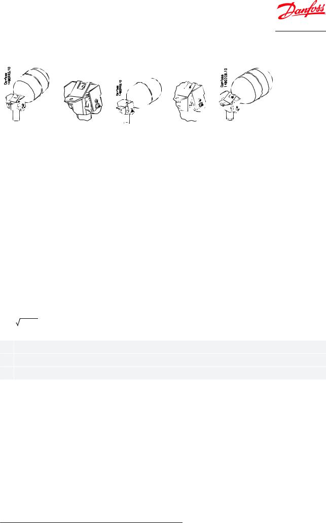
Figure 2: Identification:
Pressure and temperature data
Table 1: Pressure and temperature
Description |
Values |
|
Temperature range |
-50 °C / +80 °C (–58 °F /+176 °F) |
|
The float valve is designed for: Maximum operating pressure |
Housing PED 28 bar (407 psig) |
|
Ball (float) 25 bar (363 psig) |
||
|
||
|
|
If test pressure exceeds 25 bar (363 psi g) the ball should be removed during test.
Valves for higher pressure are available on request.
The principle of high pressure control
Introduction
In installations with one application high pressure control is an effective and cost saving way of expanding liquid from the condenser to the low pressure side.
High pressure refrigerant entering the condenser will start to condense, consequently condensate will accumulate at the bottom of the condenser and in the float valve.
When capacity demands increase, the liquid level in the float valve will rise, which will cause the valve to open and the refrigerant to expand into the separator at the low pressure side.
When the valve is closed, there will still be a small by-pass over the seat, so any remaining liquid will equalize slowly to the low pressure side, for instance during an off cycle. Therefore the system will equalize automatically and the compressor can start up without excessive back pressure. The size of the bypass is predetermined and de„ned by geometry of the elements.
It follows from the above, that almost all the refrigerant will be accumulated on the low pressure side under normal conditions. Therefore under normal conditions no high pressure receiver is necessary when using the HFI for high pressure control.
© Danfoss | Climate Solutions | 2021.09 |
AI220786430153en-001101 | 4 |
Float valve, type HFI
Insert for the high pressure €oat valve
Figure 3: Detail A Fully closed |
|
Figure 4: Detail B Fully open |
||
|
|
|
|
|
|
|
|
|
|
|
|
|
|
|
|
|
|
|
|
Computation and selection
In R 717 plants (ammonia)
On the following pages you will „nd tables with capacities of the float valve at various operating conditions.
Select a valve using the speci„c operating conditions. The chosen valve must have a capacity higher than the required capacity during nominal operation, as well as during plant start up.
In plants using other refrigerants than ammonia
The capacity of the float valve can be calculated by using the values and the equation to the right. However, the density of the refrigerant must be in the range: 500 to 700 kg/m3.
For densities outside this range please contact your local Danfoss Sales Company.
Table 2: Valve capacity values
|
Nominal capacity |
|
Valve type |
[kW] |
Valve constant [K] |
|
(R 717, –10/+35°C) |
|
HFI 040 FD |
400 |
16.79 |
HFI 050 FD |
800 |
33.58 |
HFI 060 FD |
1200 |
50.36 |
HFI 070 FD |
2400 |
100 |
|
|
|
Mass flow
G = K Δp × ρ
[kg / h]
Δp differential pressure [bar]
ρdensity of liquid [kg/m3]
K valve constant (from the above table)
Computation and selection capacity tables - SI units
Table 3: HFI 040 - R 717, evaporating capacity [kW]
|
Condens |
|
|
|
|
|
Evaporating temperature (°C) |
|
|
|
|
|
||
|
ing temp. |
–40 |
–35 |
–30 |
–25 |
–20 |
–15 |
–10 |
–5 |
0 |
5 |
10 |
15 |
20 |
|
(°C) |
|||||||||||||
|
|
|
|
|
|
|
|
|
|
|
|
|
|
|
|
50 |
475 |
480 |
480 |
475 |
475 |
475 |
470 |
460 |
455 |
445 |
430 |
415 |
395 |
|
45 |
460 |
460 |
460 |
460 |
455 |
455 |
445 |
440 |
430 |
420 |
405 |
385 |
360 |
|
40 |
440 |
440 |
440 |
440 |
435 |
430 |
425 |
415 |
405 |
390 |
375 |
350 |
325 |
|
35 |
420 |
420 |
420 |
415 |
415 |
405 |
400 |
390 |
375 |
360 |
340 |
315 |
280 |
|
30 |
400 |
400 |
400 |
395 |
390 |
385 |
375 |
360 |
345 |
325 |
300 |
270 |
|
|
25 |
380 |
380 |
375 |
370 |
365 |
360 |
345 |
330 |
315 |
290 |
260 |
230 |
|
|
220 |
|||||||||||||
|
20 |
360 |
355 |
355 |
350 |
340 |
330 |
315 |
300 |
280 |
250 |
210 |
160 |
|
|
155 |
|||||||||||||
|
15 |
340 |
335 |
330 |
325 |
315 |
300 |
285 |
265 |
240 |
200 |
150 |
|
|
|
|
|
||||||||||||
|
10 |
315 |
310 |
305 |
295 |
285 |
270 |
250 |
|
|
|
|
|
|
|
5 |
290 |
285 |
280 |
270 |
255 |
240 |
225 |
|
|
|
|
|
|
|
215 |
195 |
|
|
|
|
||||||||
|
0 |
270 |
260 |
255 |
240 |
225 |
205 |
185 |
140 |
|
|
|
||
|
175 |
135 |
|
|
|
|||||||||
|
–5 |
245 |
235 |
225 |
210 |
190 |
165 |
125 |
|
|
|
|
||
|
120 |
|
|
|
|
|
||||||||
|
–10 |
220 |
210 |
200 |
180 |
155 |
115 |
|
|
|
|
|
|
|
|
|
|
|
|
|
|
|
|||||||
|
|
|
|
|
|
|
|
|
|
|
|
|
|
|
© Danfoss | Climate Solutions | 2021.09 |
AI220786430153en-001101 | 5 |

Float valve, type HFI
Table 4: HFI 050 - R 717, evaporating capacity [kW]
|
Condens |
|
|
|
|
|
Evaporating temperature (°C) |
|
|
|
|
|
||
|
ing temp. |
–40 |
–35 |
–30 |
–25 |
–20 |
–15 |
–10 |
–5 |
0 |
5 |
10 |
15 |
20 |
|
(°C) |
|||||||||||||
|
|
|
|
|
|
|
|
|
|
|
|
|
|
|
|
50 |
955 |
955 |
955 |
955 |
950 |
945 |
935 |
925 |
910 |
890 |
865 |
830 |
790 |
|
45 |
920 |
920 |
920 |
915 |
910 |
905 |
895 |
880 |
860 |
835 |
805 |
770 |
725 |
|
40 |
880 |
880 |
880 |
875 |
870 |
860 |
850 |
830 |
810 |
780 |
745 |
700 |
645 |
|
35 |
845 |
845 |
840 |
835 |
825 |
815 |
800 |
780 |
755 |
720 |
680 |
625 |
560 |
|
30 |
805 |
800 |
800 |
790 |
780 |
765 |
750 |
725 |
695 |
655 |
605 |
540 |
|
|
25 |
765 |
760 |
755 |
745 |
730 |
715 |
695 |
665 |
630 |
580 |
520 |
455 |
|
|
440 |
|||||||||||||
|
20 |
720 |
715 |
705 |
695 |
680 |
660 |
635 |
600 |
555 |
500 |
420 |
320 |
|
|
310 |
|||||||||||||
|
15 |
675 |
670 |
660 |
645 |
630 |
605 |
570 |
530 |
480 |
405 |
295 |
|
|
|
|
|
||||||||||||
|
10 |
630 |
625 |
610 |
595 |
570 |
545 |
505 |
|
|
|
|
|
|
|
5 |
585 |
575 |
560 |
540 |
515 |
480 |
455 |
|
|
|
|
|
|
|
430 |
385 |
|
|
|
|
||||||||
|
0 |
540 |
525 |
505 |
485 |
450 |
405 |
365 |
285 |
|
|
|
||
|
345 |
270 |
|
|
|
|||||||||
|
–5 |
490 |
475 |
455 |
425 |
385 |
325 |
255 |
|
|
|
|
||
|
240 |
|
|
|
|
|
||||||||
|
–10 |
440 |
420 |
395 |
360 |
305 |
230 |
|
|
|
|
|
|
|
|
|
|
|
|
|
|
|
|||||||
|
|
|
|
|
|
|
|
|
|
|
|
|
|
|
Table 5: HFI 060 - R 717, evaporating capacity [kW]
|
Condens |
|
|
|
|
|
Evaporating temperature (°C) |
|
|
|
|
|
||
|
ing temp. |
–40 |
–35 |
–30 |
–25 |
–20 |
–15 |
–10 |
–5 |
0 |
5 |
10 |
15 |
20 |
|
(°C) |
|||||||||||||
|
|
|
|
|
|
|
|
|
|
|
|
|
|
|
|
50 |
1430 |
1435 |
1435 |
1430 |
1425 |
1420 |
1405 |
1385 |
1365 |
1335 |
1295 |
1245 |
1190 |
|
45 |
1380 |
1380 |
1380 |
1375 |
1370 |
1360 |
1340 |
1320 |
1290 |
1255 |
1210 |
1155 |
1085 |
|
40 |
1325 |
1325 |
1320 |
1315 |
1305 |
1290 |
1270 |
1245 |
1215 |
1170 |
1120 |
1055 |
970 |
|
35 |
1265 |
1265 |
1260 |
1250 |
1240 |
1220 |
1200 |
1170 |
1130 |
1080 |
1020 |
940 |
840 |
|
30 |
1205 |
1205 |
1195 |
1185 |
1170 |
1150 |
1120 |
1085 |
1040 |
980 |
905 |
810 |
|
|
25 |
1145 |
1140 |
1130 |
1115 |
1100 |
1075 |
1040 |
995 |
940 |
870 |
780 |
685 |
|
|
660 |
|||||||||||||
|
20 |
1080 |
1070 |
1060 |
1045 |
1020 |
990 |
950 |
900 |
835 |
750 |
635 |
485 |
|
|
465 |
|||||||||||||
|
15 |
1015 |
1005 |
990 |
970 |
940 |
905 |
860 |
795 |
715 |
605 |
445 |
|
|
|
|
|
||||||||||||
|
10 |
945 |
935 |
915 |
890 |
860 |
815 |
755 |
|
|
|
|
|
|
|
5 |
875 |
860 |
840 |
810 |
770 |
720 |
680 |
|
|
|
|
|
|
|
645 |
580 |
|
|
|
|
||||||||
|
0 |
805 |
785 |
760 |
725 |
675 |
610 |
550 |
425 |
|
|
|
||
|
520 |
405 |
|
|
|
|||||||||
|
–5 |
735 |
710 |
680 |
635 |
575 |
490 |
380 |
|
|
|
|
||
|
360 |
|
|
|
|
|
||||||||
|
–10 |
660 |
635 |
595 |
540 |
460 |
340 |
|
|
|
|
|
|
|
|
|
|
|
|
|
|
|
|||||||
|
|
|
|
|
|
|
|
|
|
|
|
|
|
|
Table 6: HFI 070 - R717, evaporating capacity [kW]
|
Condens |
|
|
|
|
|
Evaporating temperature (°C) |
|
|
|
|
|
||
|
ing temp. |
–40 |
–35 |
–30 |
–25 |
–20 |
–15 |
–10 |
–5 |
0 |
5 |
10 |
15 |
20 |
|
(°C) |
|||||||||||||
|
|
|
|
|
|
|
|
|
|
|
|
|
|
|
|
50 |
|
|
|
|
|
|
2680 |
2775 |
2725 |
2665 |
2590 |
2495 |
2375 |
|
45 |
|
|
|
|
|
|
2640 |
2580 |
2510 |
2420 |
2310 |
2170 |
|
|
|
|
|
|
|
2445 |
2545 |
|||||||
|
40 |
|
|
|
|
|
2490 |
2425 |
2340 |
2235 |
2105 |
1940 |
||
|
|
|
|
|
|
|
2400 |
|||||||
|
35 |
|
|
|
|
|
|
2335 |
2260 |
2160 |
2035 |
1880 |
1680 |
|
|
|
|
|
|
|
|
|
|||||||
|
30 |
|
|
|
|
2340 |
2300 |
2245 |
2170 |
2080 |
1960 |
1815 |
1625 |
|
|
25 |
|
|
|
2090 |
2195 |
2145 |
2080 |
1995 |
1885 |
1745 |
1565 |
1370 |
|
|
|
|
|
1320 |
||||||||||
|
20 |
|
|
|
1940 |
2040 |
1980 |
1900 |
1800 |
1670 |
1500 |
1265 |
965 |
|
|
|
|
|
930 |
||||||||||
|
15 |
|
|
|
|
1885 |
1810 |
1715 |
1595 |
1435 |
1210 |
890 |
|
|
|
|
|
|
|
|
|
||||||||
|
10 |
|
1725 |
1835 |
1785 |
1715 |
1630 |
1515 |
|
|
|
|
|
|
|
5 |
|
1680 |
1620 |
1540 |
1435 |
1365 |
|
|
|
|
|
||
|
1470 |
1575 |
1295 |
1160 |
|
|
|
|
||||||
|
0 |
1520 |
1450 |
1350 |
1220 |
1100 |
850 |
|
|
|
||||
|
1325 |
1425 |
1040 |
810 |
|
|
|
|||||||
|
–5 |
1360 |
1270 |
1150 |
980 |
765 |
|
|
|
|
||||
|
|
1265 |
725 |
|
|
|
|
|
||||||
|
–10 |
|
1190 |
1080 |
920 |
685 |
|
|
|
|
|
|
||
|
|
|
|
|
|
|
|
|
|
|||||
|
|
|
|
|
|
|
|
|
|
|
|
|
|
|
Table 7: HFI 040 - R 717, evaporating capacity [TR]
|
Condens |
|
|
|
|
|
Evaporating temperature (°F) |
|
|
|
|
|
||
|
ing temp. |
–40 |
–30 |
–20 |
–10 |
0 |
10 |
20 |
30 |
40 |
50 |
60 |
70 |
80 |
|
(°F) |
|||||||||||||
|
|
|
|
|
|
|
|
|
|
|
|
|
|
|
|
120 |
134 |
135 |
135 |
134 |
134 |
132 |
131 |
128 |
125 |
121 |
116 |
109 |
101 |
|
110 |
129 |
129 |
129 |
128 |
127 |
126 |
123 |
121 |
117 |
112 |
106 |
98 |
87 |
|
100 |
123 |
123 |
122 |
122 |
120 |
118 |
116 |
112 |
108 |
102 |
94 |
84 |
71 |
|
90 |
117 |
117 |
116 |
115 |
113 |
111 |
107 |
103 |
98 |
91 |
81 |
69 |
50 |
|
80 |
110 |
110 |
109 |
107 |
105 |
102 |
99 |
94 |
87 |
78 |
|
|
|
|
70 |
103 |
103 |
102 |
100 |
97 |
94 |
89 |
83 |
75 |
66 |
|
|
|
|
63 |
49 |
|
|||||||||||
|
60 |
97 |
96 |
94 |
92 |
89 |
84 |
79 |
71 |
60 |
47 |
|
||
|
44 |
|
|
|||||||||||
|
50 |
90 |
88 |
86 |
83 |
80 |
74 |
67 |
57 |
42 |
|
|
|
|
|
|
|
|
|
||||||||||
|
40 |
82 |
81 |
78 |
75 |
70 |
63 |
|
|
|
|
|
|
|
|
30 |
75 |
73 |
70 |
65 |
59 |
54 |
|
|
|
|
|
|
|
|
51 |
40 |
|
|
|
|
|
|||||||
|
20 |
67 |
65 |
61 |
55 |
47 |
38 |
|
|
|
|
|
||
|
35 |
|
|
|
|
|
|
|||||||
|
10 |
59 |
56 |
51 |
44 |
33 |
|
|
|
|
|
|
|
|
|
|
|
|
|
|
|
|
|
||||||
|
|
|
|
|
|
|
|
|
|
|
|
|
|
|
© Danfoss | Climate Solutions | 2021.09 |
AI220786430153en-001101 | 6 |
 Loading...