


Danfoss HHP015T4LP6, HHP015T5LP6, HHP019T4LP6, HHP019T5LP6, HHP021T4LP6 Application guide
...Application guidelines
Danfoss Heat Pump scroll compressors, HHP-Series
50Hz - R407C
http://cc.danfoss.com

Application Guidelines |
Content |
|
|
Scroll compression principle............................................................................................ |
6 |
Scroll compressor components................................................................................................................................. |
6 |
The scroll compression process................................................................................................................................. |
7 |
Performance...................................................................................................................................................................... |
7 |
Compressor model designation....................................................................................... |
8 |
Nomenclature................................................................................................................................................................... |
8 |
Label..................................................................................................................................................................................... |
8 |
Technical specifications.................................................................................................... |
9 |
50-Hz data.......................................................................................................................................................................... |
9 |
Performance table........................................................................................................................................................... |
9 |
Dimensions....................................................................................................................... |
10 |
HHP015-019-021-026.................................................................................................................................................... |
10 |
HHP030-038-045............................................................................................................................................................ |
11 |
Electrical data, connections and wiring......................................................................... |
12 |
Motor voltage.................................................................................................................................................................. |
12 |
Wiring connections........................................................................................................................................................ |
12 |
IP rating.............................................................................................................................................................................. |
13 |
LRA (Locked Rotor Amp).............................................................................................................................................. |
13 |
MCC (Maximum Continuous Current).................................................................................................................... |
13 |
Max Oper. A (Maximum Operating Amp).............................................................................................................. |
13 |
Winding resistance........................................................................................................................................................ |
13 |
Electrical connections................................................................................................................................................... |
13 |
Nominal capacitor value.............................................................................................................................................. |
14 |
Internal motor protection........................................................................................................................................... |
14 |
Phase sequence and reverse rotation protection............................................................................................... |
14 |
Voltage imbalance ........................................................................................................................................................ |
14 |
Approvals and certifications........................................................................................... |
15 |
Approvals and certificates........................................................................................................................................... |
15 |
Pressure equipment directive 97/23/EC................................................................................................................ |
15 |
Low voltage directive 73/23/EC, 93/68/EC............................................................................................................ |
15 |
Internal free volume...................................................................................................................................................... |
15 |
Operating conditions....................................................................................................... |
16 |
Refrigerant and lubricants.......................................................................................................................................... |
16 |
Motor supply.................................................................................................................................................................... |
16 |
Compressor ambient temperature.......................................................................................................................... |
16 |
Application envelope.................................................................................................................................................... |
17 |
R407C ................................................................................................................................................................................. |
17 |
Maximum discharge gas temperature................................................................................................................... |
17 |
High and low pressure protection........................................................................................................................... |
18 |
On/off cycling (cycle rate limit)................................................................................................................................. |
18 |
4 FRCC.PC.017.A2.02

Application Guidelines |
Content |
|
|
System design recommendations................................................................................... |
19 |
General............................................................................................................................................................................... |
19 |
Essential piping design considerations.................................................................................................................. |
19 |
Refrigerant charge limit .............................................................................................................................................. |
20 |
Reversible heat pump systems.................................................................................................................................. |
20 |
Crankcase heater............................................................................................................................................................ |
22 |
Minimum sump superheat......................................................................................................................................... |
22 |
Loss of charge protection............................................................................................................................................ |
22 |
Oil level checking and top-up.................................................................................................................................... |
22 |
High pressure ratio........................................................................................................................................................ |
22 |
Preventing liquid flood back...................................................................................................................................... |
22 |
Testing for excessive liquid flood back................................................................................................................... |
22 |
Water utilising systems................................................................................................................................................. |
22 |
Sound and vibration management................................................................................. |
23 |
Running sound level..................................................................................................................................................... |
23 |
Sound generation in a refrigeration system / air conditioning system...................................................... |
23 |
Compressor sound radiation...................................................................................................................................... |
23 |
Mechanical vibrations................................................................................................................................................... |
23 |
Gas pulsation................................................................................................................................................................... |
23 |
Installation........................................................................................................................ |
24 |
System cleanliness......................................................................................................................................................... |
24 |
Compressor handling and storage.......................................................................................................................... |
24 |
Compressor mounting................................................................................................................................................. |
24 |
Compressor holding charge....................................................................................................................................... |
24 |
Tube brazing procedure.............................................................................................................................................. |
24 |
Brazing material.............................................................................................................................................................. |
24 |
Vacuum evacuation and moisture removal.......................................................................................................... |
25 |
Liquid line filter driers................................................................................................................................................... |
26 |
Refrigerant charging..................................................................................................................................................... |
26 |
Insulation resistance and dielectric strength....................................................................................................... |
26 |
Compressor replacement after motor burn out................................................................................................. |
26 |
Ordering information and packaging............................................................................ |
27 |
Packaging.......................................................................................................................................................................... |
27 |
Packaging details........................................................................................................................................................... |
27 |
Ordering information and packaging..................................................................................................................... |
27 |
Spare parts & accessories................................................................................................ |
28 |
Run capacitors for PSC wiring.................................................................................................................................... |
28 |
Rotolock adaptor set..................................................................................................................................................... |
28 |
Rotolock adaptor............................................................................................................................................................ |
28 |
Crankcase heater............................................................................................................................................................ |
28 |
Discharge temperature protection.......................................................................................................................... |
29 |
Lubricant........................................................................................................................................................................... |
29 |
Mounting hardware...................................................................................................................................................... |
29 |
FRCC.PC.017.A2.02 5

Application Guidelines |
Scroll compression principle |
|
|
Scroll compressor |
The motor stator is rigidly attached to the shell. |
components |
The rotor is shrink-fit onto the eccentric shaft. The |
shaft is supported by two bearings, one in the crankcase and the second below the motor.
6 FRCC.PC.017.A2.02
Application Guidelines |
Scroll compression principle |
|
|
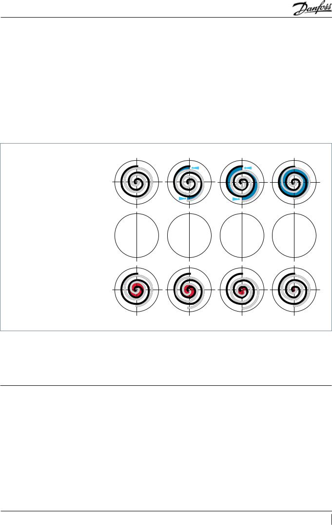
The scroll compression process
The entire scroll compression process is illustrated below. The centre of the orbiting scroll traces a circular path around the centre of the fixed scroll. This movement creates compression pockets between the two scroll elements.
Low pressure suction gas is trapped within each crescent-shaped pocket as it forms; continuous motion of the orbiting scroll serves to seal the pocket, which decreases in volume as the
pocket moves towards the centre of the scroll set, with corresponding increase in gas pressure. Maximum compression is achieved, as the pocket reaches the discharge port at the centre.
Scroll compression is a continuous process: when one pocket of gas is being compressed during the second orbit, another gas quantity enters a new pocket formed at the periphery, and simultaneously, another is being discharged.
SUCTION
COMPRESSION 


DISCHARGE
Danfoss Heat Pump scroll compressors are manufactured using the most advanced machining, assembly, and process control techniques. In design of both the compressor
and the factory, very high standards of reliability and process control were first priority. The result is a highly efficient product with the highest reliability obtainable, and a low sound level.
Performance |
The |
Danfoss |
Heat |
Pump |
scroll |
compressor |
|
|
referenced |
in |
this |
guide is a fully compliant |
|||
|
scroll |
and |
actually |
improves |
with |
run time in |
|
it's early commissioning. A seventy-two hour run-in is recommended to meet performance expectations.
FRCC.PC.017.A2.02 7

Application Guidelines Compressor model designation
Nomenclature |
|
|
|
|
|
|
|
|
Type |
Size |
Motor |
Features |
|
|
|
|
|
HHP |
030 |
T4L |
P6 |
|
|
|
|
|
Application: |
|
|
|
Other features |
|
|
|
|
H: high temperature |
|
|
|
Oil sight |
Oil equali- |
Oil |
LP gauge |
Gas equali- |
|
|
|
|
|||||
|
|
|
|
glass |
sation |
drain |
port |
sation port |
Family: |
|
|
6 |
None |
None |
None |
None |
None |
HP: heat pump R407C PVE |
|
|
|
Tubing and electrical connections |
|
|||
|
|
|
|
|
||||
|
|
|
|
P: brazed connections, spade terminals |
|
|||
Nominal capacity: |
|
|
|
C: brazed connections, screw terminals |
|
|||
|
|
|
|
Motor protection |
|
|
|
|
|
|
|
|
L: internal motor protection |
|
|
||
Model variation |
|
|
|
Motor voltage code |
|
|
|
|
T motor design |
|
|
|
4: 380-400V/3~/50 Hz |
|
|
||
|
|
|
|
5: 220-240V/1~/50 Hz |
|
|
||
Label |
|
|
|
|
|
|
|
|
Serial number
|
S 03 09 |
K 12345 |
||||||||||||||
|
|
|
|
|
|
|
|
|
|
|
|
|
|
|
|
|
Production week |
|
|
|
|
|
|
|
|
|
|
|
|
|
Incremental number |
||
|
|
|
|
|
|
|
|
|
|
|
|
|||||
Production year |
|
|
|
|
|
|
|
|
|
|
|
|
Manufacturing location |
|||
|
|
|
|
|
|
|
|
|
|
|
|
|||||
8 FRCC.PC.017.A2.02

Application Guidelines |
Technical specifications |
|
|
|
|
|
|||
|
|
|
|
|
|
|
|
|
|
50-Hz data |
|
|
|
|
|
|
|
|
|
|
Heating |
Power input |
Max. A. |
Heating |
Swept volume |
Displacement |
Oil charge |
Net weight |
|
Model |
capacity |
efficiency |
|||||||
|
|
|
|
|
|
||||
|
|
|
|
|
m3/hr @2900 |
|
|
||
|
W |
W |
A |
COP W/W |
(cm3/rev) |
L |
kg |
||
|
|
|
|
|
|
rpm |
|
|
|
HHP015T4LP6 |
4800 |
1540 |
5.1 |
3.13 |
34 |
5.9 |
1.06 |
31 |
|
HHP015T5LP6 |
4880 |
1660 |
14.2 |
2.93 |
34 |
5.9 |
1.06 |
31 |
|
HHP019T4LP6 |
5780 |
1910 |
5.8 |
3.02 |
41 |
7.1 |
1.06 |
33 |
|
HHP019T5LP6 |
5830 |
2040 |
17.7 |
2.86 |
41 |
7.1 |
1.06 |
33 |
|
HHP021T4LP6 |
6410 |
2030 |
5.8 |
3.16 |
46 |
8 |
1.06 |
33 |
|
HHP021T5LP6 |
6630 |
2110 |
18.2 |
3.15 |
46 |
8 |
1.06 |
33 |
|
HHP026T4LP6 |
8100 |
2520 |
7.1 |
3.22 |
57 |
10 |
1.06 |
33 |
|
HHP026T5LP6 |
8160 |
2680 |
22.7 |
3.04 |
57 |
10 |
1.06 |
33 |
|
HHP030T4LC6 |
9700 |
3070 |
8.6 |
3.17 |
67 |
11.7 |
1.57 |
33 |
|
HHP030T5LC6 |
9790 |
3190 |
27.7 |
3.07 |
67 |
11.7 |
1.57 |
42 |
|
HHP038T4LC6 |
12050 |
3730 |
10.8 |
3.23 |
82 |
14.2 |
1.57 |
42 |
|
HHP038T5LC6 |
12140 |
3850 |
35.2 |
3.16 |
82 |
14.2 |
1.57 |
42 |
|
HHP045T4LC6 |
13940 |
4300 |
12.6 |
3.25 |
99 |
17.2 |
1.57 |
42 |
|
|
|
|
|
|
|
|
|
|
|
Evaporating temperature: -7° C |
Condensing temperature: 50°C |
Superheat: 10 K |
Subcooling: 5 K |
Subject to modification without prior notification |
Conditions: 400V/3ph/50Hz (motor T4), 230V/1ph/50 Hz (motor T5) |
||
For full data details and capacity tables refer to Online Datasheet Generator : www.danfoss.com/odsg |
|
||
Performance table
Model |
To |
-25 |
|
-20 |
|
-15 |
|
-10 |
|
-5 |
|
0 |
|
5 |
|
10 |
|
15 |
|
|
Tc |
H |
Pe |
H |
Pe |
H |
Pe |
H |
Pe |
H |
Pe |
H |
Pe |
H |
Pe |
H |
Pe |
H |
Pe |
||
|
||||||||||||||||||||
|
40 |
2 550 |
1.1 |
3 070 |
1.1 |
3 720 |
1.2 |
4 510 |
1.3 |
5 450 |
1.3 |
6 520 |
1.4 |
7 730 |
1.4 |
9 080 |
1.4 |
10 570 |
1.4 |
|
HHP015T4 |
50 |
2 620 |
1.5 |
3 050 |
1.5 |
3 620 |
1.5 |
4 320 |
1.5 |
5 150 |
1.6 |
6 120 |
1.6 |
7 220 |
1.7 |
8 460 |
1.7 |
9 840 |
1.7 |
|
|
60 |
- |
- |
- |
- |
3 860 |
2.2 |
4 410 |
2.1 |
5 090 |
2.1 |
5 890 |
2.1 |
6 830 |
2.1 |
7 900 |
2.1 |
9 100 |
2.1 |
|
|
40 |
3 070 |
1.3 |
3 680 |
1.4 |
4 450 |
1.5 |
5 400 |
1.5 |
6 520 |
1.6 |
7 810 |
1.7 |
9 270 |
1.7 |
10 900 |
1.7 |
12 690 |
1.7 |
|
HHP019T4 |
50 |
3 180 |
1.7 |
3 680 |
1.7 |
4 340 |
1.8 |
5 180 |
1.9 |
6 180 |
1.9 |
7 340 |
2.0 |
8 670 |
2.1 |
10 160 |
2.2 |
11 830 |
2.2 |
|
|
60 |
- |
- |
- |
- |
4 660 |
2.3 |
5 300 |
2.4 |
6 110 |
2.4 |
7 070 |
2.5 |
8 200 |
2.6 |
9 480 |
2.7 |
10 930 |
2.8 |
|
|
40 |
3 530 |
1.4 |
4 250 |
1.5 |
5 090 |
1.6 |
6 080 |
1.7 |
7 230 |
1.7 |
8 570 |
1.8 |
10 100 |
1.8 |
11 840 |
1.7 |
13 820 |
1.7 |
|
HHP021T4 |
50 |
3 430 |
1.6 |
4 080 |
1.8 |
4 860 |
1.9 |
5 770 |
2.0 |
6 830 |
2.1 |
8 070 |
2.1 |
9 500 |
2.2 |
11 140 |
2.2 |
13 000 |
2.2 |
|
|
60 |
- |
- |
- |
- |
4 710 |
2.2 |
5 530 |
2.3 |
6 510 |
2.5 |
7 650 |
2.6 |
8 970 |
2.7 |
10 490 |
2.8 |
12 240 |
2.8 |
|
|
40 |
4 540 |
1.7 |
5 410 |
1.9 |
6 440 |
2.0 |
7 650 |
2.1 |
9 070 |
2.1 |
10 740 |
2.2 |
12 690 |
2.2 |
14 950 |
2.1 |
17 550 |
2.0 |
|
HHP026T4 |
50 |
4 590 |
2.0 |
5 350 |
2.1 |
6 260 |
2.3 |
7 330 |
2.4 |
8 610 |
2.6 |
10 120 |
2.6 |
11 900 |
2.7 |
13 970 |
2.7 |
16 370 |
2.7 |
|
|
60 |
- |
- |
- |
- |
6 240 |
2.7 |
7 150 |
2.9 |
8 250 |
3.0 |
9 560 |
3.2 |
11 130 |
3.3 |
12 980 |
3.3 |
15 150 |
3.3 |
|
|
40 |
4 910 |
2.1 |
6 100 |
2.3 |
7 480 |
2.4 |
9 050 |
2.6 |
10 830 |
2.6 |
12 830 |
2.7 |
15 060 |
2.7 |
17 520 |
2.8 |
20 240 |
2.9 |
|
HHP030T4 |
50 |
4 830 |
2.3 |
5 940 |
2.6 |
7 230 |
2.8 |
8 690 |
3.0 |
10 350 |
3.1 |
12 200 |
3.2 |
14 270 |
3.4 |
16 560 |
3.5 |
19 090 |
3.6 |
|
|
60 |
- |
- |
- |
- |
7 000 |
3.1 |
8 330 |
3.4 |
9 850 |
3.6 |
11 550 |
3.8 |
13 440 |
4.0 |
15 540 |
4.2 |
17 870 |
4.4 |
|
|
40 |
6 150 |
2.4 |
7 600 |
2.8 |
9 360 |
3.0 |
11 390 |
3.2 |
13 660 |
3.2 |
16 130 |
3.3 |
18 750 |
3.3 |
21 510 |
3.4 |
24 360 |
3.6 |
|
HHP038T4 |
50 |
5 730 |
2.2 |
7 120 |
2.8 |
8 800 |
3.3 |
10 740 |
3.6 |
12 890 |
3.8 |
15 220 |
4.0 |
17 700 |
4.1 |
20 280 |
4.2 |
22 940 |
4.4 |
|
|
60 |
- |
- |
- |
- |
8 090 |
3.2 |
9 930 |
3.8 |
11 970 |
4.2 |
14 170 |
4.5 |
16 500 |
4.7 |
18 920 |
5.0 |
21 400 |
5.2 |
|
|
40 |
7 110 |
3.0 |
8 800 |
3.1 |
10 830 |
3.3 |
13 180 |
3.5 |
15 800 |
3.7 |
18 660 |
3.8 |
21 700 |
3.9 |
24 890 |
3.8 |
28 180 |
3.7 |
|
HHP045T4 |
50 |
6 630 |
3.5 |
8 240 |
3.7 |
10 190 |
3.9 |
12 420 |
4.2 |
14 910 |
4.4 |
17 610 |
4.6 |
20 480 |
4.7 |
23 460 |
4.8 |
26 540 |
4.8 |
|
|
60 |
- |
- |
- |
- |
9 360 |
4.5 |
11 490 |
4.8 |
13 850 |
5.1 |
16 400 |
5.5 |
19 100 |
5.7 |
21 890 |
6.0 |
24 760 |
6.1 |
|
Legend: |
|
To: Evaporating temperature in °C |
|
H: Heating capacity in W |
|
|
Superheat = 5 K |
|
|
|
||||||||||
|
|
Tc: Condensing temperature in °C |
|
Pe: Power input in kW |
|
|
Subcooling = 5 K |
|
|
|
||||||||||
FRCC.PC.017.A2.02 9
Application Guidelines |
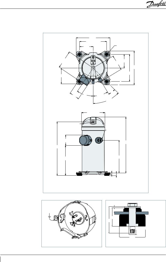
Dimensions |
|
|
HHP015-019-021-026
|
|
238.8 |
|
|
190.25 - 190.75 |
|
|
|
95.25 |
4 x Ø 19.0 - 20.0 |
|
|
|
||
128.5 |
|
|
95.25 |
|
|
|
109.7 |
|
|
|
238.8 |
111.3 |
|
|
190.25 - 190.50 |
|
|
|
|
|
|
|
14° |
69.4 - 71.4 |
34° |
31° |
|
|
|
|
|
|
|
|
45° |
|
|
163.5 - 165.5 |
|
Discharge line 12.75-12.85
(1/2 inch) Suction line
(1) 19.13-19.23 (3/4 inch)
72.1 - 75.1
394.4
360.4
194.9 |
230.8 |
|
|
|
10.7 |
19 P6
HHP 015-019-021-026
All dimensions in mm
Terminal box
Quick connect spade terminals
P terminal box type
Mounting grommet
1.7
29.5
41


 5/16” - 18 UNC
self tapping
Ø11
Ø 41
Recommended torque for mounting bolts: 11 Nm (±1 Nm)
Refer to section "Spare parts and accessories" for overview of shipped mounting accessories
10 FRCC.PC.017.A2.02
 Loading...