


Aluminium Hiking Poles
Aluminium Hiking Poles
Instructions for use
Aluminiowe kijki do trekkingu
Instrukcja obsługi
Aluminijaste pohodne palice
Navodilo za uporabo
ALUMINIUM-TREKKINGSTÖCKE
Bedienungsanleitung
|
|
|
|
|
IAN 103778 |
1 |
|
|
|
||
|
|
||
|
|
|
|

Congratulations on purchasing this high-quality product. Be sure to familiarise yourself with the assembly instructions prior to use.
Please take the time to carefully read through the following assembly instructions and safety notes. Only use the product as described and for the intended use. Please retain these instructions for future reference and ensure that they are passed on to any third party.
Use
This hiking pole is equipped with a hardened metal tip and is intended for hiking in the countryside, on ice or on other smooth surfaces.
It is also equipped with an asphalt pad which can be attached and removed easily when hiking on asphalt or other hard surfaces.
Parts List
A |
1 |
(1) |
Strap adjustment system |
|
|
|
|||
|
2 |
(2) |
Wrist strap |
|
10 |
(3) |
Asphalt pad |
||
9 |
|
|||
3 |
(4) |
Combo bracket |
||
8 |
||||
4 |
(5) |
Height adjustment system |
||
|
|
(6) |
Hollow ground tip |
|
|
|
(7) |
Hiking pole |
7
5
6 

 Safety notice
(8)Basket
(9)Clip for connecting the poles
(10)Ergonomic 2 component handle
Technical data
Length: adjustable 66 - 135cm
Weight: one trekking pole approx. 278g Maximum weight: 140kg
Material: aluminium
•Do not attempt any repairs that might put your safety at risk.
•We recommend using a heart rate monitor.
•Consult your doctor before engaging in sports activities if you have a known cardiovascular problem.
•Use sports shoes with treaded soles and supportive sides.
•Avoid sporting activities in the dark or use reflectors worn on the body at dusk.
•Check the screws on the hiking pole before use.
•Check the hiking pole for damage before use.
•As soon as you ascertain any damage in the pole segments, or anything faulty that will affect the function of the hiking pole, cease use of the pole immediately.
•If possible, avoid public roads in order to minimise risk of accidents.
•Hiking poles are not suitable for downhill skiing.
•Please do not use oil as all types of oil can negatively influence the retention force of the adjustment mechanism.
•Remember that the tip of the hiking pole may damage floors.
•Do not sit on the pole as it could break.
•Pointed poles are dangerous for children.
•This equipment is solely intended for private use. This equipment is not guaranteed for commercial use.
•During use, please check the locking system regularly.
2GB
Adjusting the pole length
Your trekking poles are height adjustable from 66 - 135cm and should be adjusted to your height and the type of use.
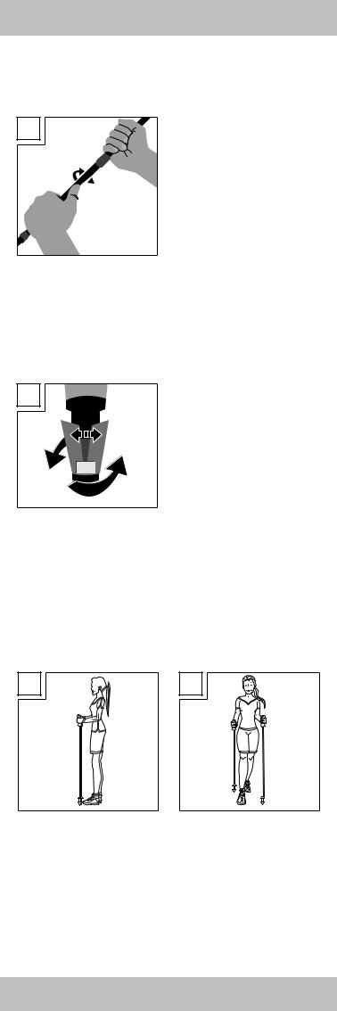
Locking/opening (Fig. B)
B
Opening
 Locking
The direction for opening and locking is already indicated at the top of the trekking pole. Hold the upper section of the pole with one hand, you will then be able to tighten the lower pole sections turning clockwise, or lock it turning counter-clockwise. Keep tightening the screw connection until you’re unable to turn it any more by typical force.
Enabling/disabling the damping system
To disable the damping system, secure the pole length as described under “Adjusting the pole length”.
Then slightly turn the centre section of the trekking pole against the locking direction. You will now hear a distinct click. The damping system is now disabled. Turn the centre section slightly in the locking direction to reactivate the damping system.
 Note:
Note:
C
•After closing check if the fasteners are secure by slightly leaning onto the pole.
•Never fasten the pole length beyond the “STOP” mark!
•When pulled very tightly the trekking pole locking system with attain a clamping force of approx. 140kg.
•Loads over 100kg with the damping system disabled may damage the damping system.
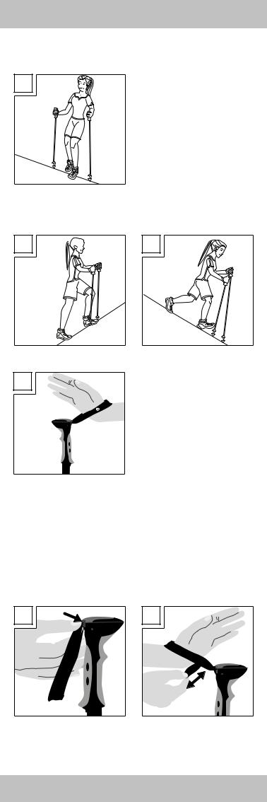
•If the pole won’t close, remove the respective pole section from the pole. Turn the locking system 2 - 3 turns by hand until the orange clamping device begins to slightly spread (see Fig. C). Then reinsert the individual pole section into the pole and secure to the desired length.
•Walking on level surfaces (Fig. D/E)
Adjust the pole length so your upper arm and forearm are at a 90° angle. Be sure to adjust the poles to the same length. The centre and bottom stock sections have pole length marks. To adjust the pole to a length of 120cm, secure the centre and bottom pole sections so the 120cm marking are just visible in the upper pole section.
D 

 E
E
GB 3
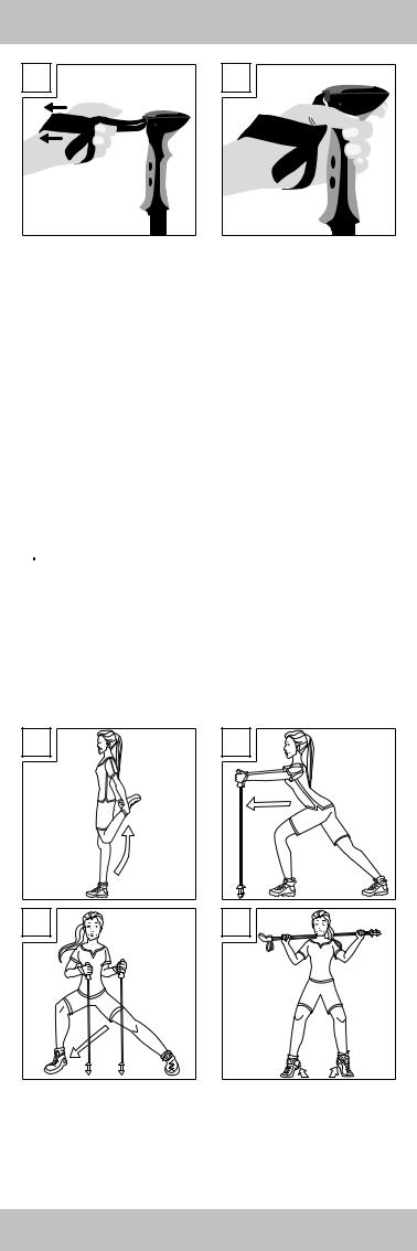
• Walking traverses (Fig. F)
Here the upper pole must be shortened and the low pole extended so both pieces can provide support.
F
• Climbing (Fig. G/H)
Ascending the poles must be shortened to present a comfortable support. Descending the poles must be extended so you are in a comfortable upright position whilst supported.
G 

 H
H
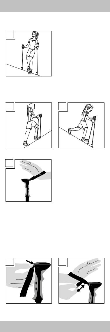
Using the strap (Fig. I)
I
Attach the strap so the back of your hand is enclosed by the top section of the strap.
The Rocktrail logo will be facing outward. Now hold the grip. Please note the wrist straps are marked “L” and “R”!
Adjusting the wrist strap (Fig. J-M)
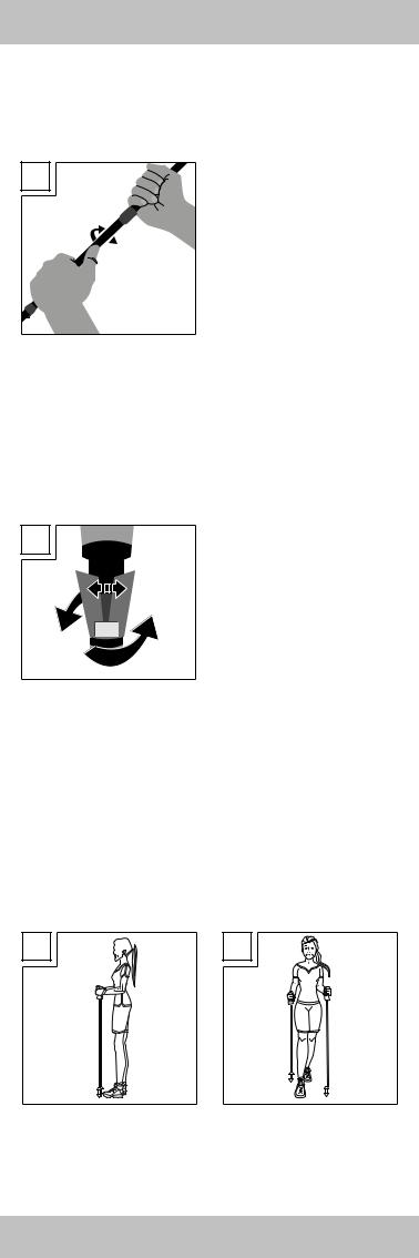
The size of the wrist strap can be adjusted using the push button. To open the locking mechanism, press the push button on the strap adjustment system with your thumb (Fig. J).
The strap is now unlocked and can be adjusted to the correct fit. Pull the open, bottom strap end to tighten the strap. Pull in the opposite direction to loosen the strap (Fig. K).
Tighten the strap by holding the pole with one hand, and with the other pull the upper loop to lock in the push button (Fig. L).
Adjust the size of the loop so it doesn’t cut when wrapping your hand around the grip (Fig. M).
J |
K |
4GB
L |
M |
Helpful hints for use
•Wear gloves in cold weather.
•Be sure to take sufficient liquids on extended outings (if necessary use a hydration belt or hydration pack).
•Dress appropriate for the weather.
Combo bracket for asphalt pad & basket
Use the combo bracket to store the asphalt pad and the trekking pole basket. The asphalt pad is used on rocky and hard surfaces, and the trekking pole basket for soft surfaces to prevent the trekking pole from sinking in. You may also remove the combo bracket. Pull the tab of the red rubber ring to remove it from the bracket guide. The bracket may now be removed from the pole. To attach the combo bracket place it on the pole, wrap the rubber band once around the pole and reinsert in the guide on the combo holder. When not using the asphalt pads or the trekking pole basket for your current route you can attach/insert them in the basket interchanging system holder.
 Warming up and stretching
You should properly warm up and stretch before trekking (see Fig. N-Q).
• Fig. N: Front thigh muscles
Draw your foot toward your bum.
• Fig. O: Rear lower leg muscles
Press your heel into the floor and lean your body slightly forward.
• Fig. P: Inside hip muscles
Slide your pelvis downward at an angle.
• Fig. Q: Calf muscles
Raise and lower your heels several times.
N |
O |
P |
Q |
GB 5

Care and cleaning
Clean the hiking poles with a cloth soaked in lukewarm or soapy water. Do not attempt to clean the poles using detergent or abrasive cleaning agents. These may permanently damage the plastic parts and printed marks.
Storage and transport
Do not leave the hiking poles exposed to direct sunlight or excessive temperatures as this could cause cracks to appear, causing them to disintegrate, reducing their lifespan and drastically reducing their use. Store the hiking poles in a dry place. Dry wet poles with a cloth before collapsing to prevent rust. Always attach the rubber bumpers to the tips when transporting the poles.
Disposal
Dispose of packaging in an environmentally friendly way. To discard of hiking poles consult your local waste management authority.
3 year warranty
The product was produced with great care and under constant supervision. You receive a three-year warranty for this product from the date of purchase. Please retain your receipt.
The warranty applies only to material and workmanship and does not apply to misuse or improper handling. Your statutory rights, especially the warranty rights, are not affected by this warranty.
With regard to complaints, please contact the following service hotline or contact us by e-mail. Our service employees will advise as to the subsequent procedure as quickly as possible. We will be personally available to discuss the situation with you.
Any repairs under the warranty, statutory guarantees or through goodwill do not extend the warranty period. This also applies to replaced and repaired parts. Repairs after the warranty are subject to a charge.
IAN: 103778
 Service Great Britain Tel.: 0871 5000 720
(10p/min) E-Mail:deltasport@lidl.co.uk
You can also find spare parts for your product at: www.delta-sport.com, category Service - Lidl Spare Parts Service
6GB

Gratulujemy! Kupując nasz artykuł zdecydowali się Państwo na produkt o wysokiej jakości. Przed montażem i pierwszym
zastosowaniem należy zapoznać się z artykułem. W tym celu prosimy o dokładne przeczytanie poniższej instrukcji dot. montażu i wskazówek bezpieczeństwa. Produkt należy stosować, jak opisano w instrukcji i tylko w podanym zakresie użycia. Instrukcję obsługi należy dokładnie przechowywać. W przypadku przekazania artykułu osobom trzecim, należy również przekazać im wszystkie dokumenty.
Zastosowanie/Przeznaczenie
Kijek trekkingowy wyposażony jest w końcówkę wykonaną z twardego metalu i przeznaczoną do użytku podczas spacerów w terenie, na lodzie lub na innych gładkich powierzchniach. Kijek wyposażony jest ponadto w nakładkę gumową do chodzenia po asfalcie, którą można w razie potrzeby w łatwy sposób nakładać i zdejmować. Kijek trekkingowy przeznaczony jest wyłącznie do spacerów.
Lista części
A |
1 |
(1) |
System regulacji pętli |
|
(2) |
Pętla na dłoń |
|||
|
2 |
|||
10 |
(3) |
Nakładki na asfalt |
||
9 |
|
|||
3 |
(4) |
Uchwyt połączenia |
||
8 |
||||
4 |
(5) |
System regulacji wysokości |
||
|
|
(6) |
Wyszlifowany grot |
|
|
|
(7) |
Kijek trekkingowy |
|
7 |
|
(8) |
Talerz |
|
|
|
(9) |
Klamra do połączenia kijków |
|
|
5 |
(10) |
Ergonomiczny 2-komponentowy |
|
|
|
uchwyt |
Dane techniczne
|
|
|
Długość: regulacja 66-135 cm |
|
|
|
Waga: jeden kijek trekkingowy ok. 278 g |
|
|
|
Maksymalne obciążenie: 140 kg |
|
|
|
Materiał: aluminium |
6 |
|
|
|
|
|
|
 Wskazówki bezpieczeństwa
•Nie należy przeprowadzać napraw, które mogłyby zagrażać bezpieczeństwu!
•Zaleca się korzystanie z urządzenia mierzącego częstotliwość uderzeń serca.
•Jeśli użytkownik ma problemy z krążeniem, przed rozpoczęciem treningu powinien skonsultować się z lekarzem.
•Należy stosować obuwie sportowe wyposażone w odpowiedni profil i boczne wsparcie.
•Unikać treningu po zmroku względnie stosować po zmroku odblaski umocowane na ubraniu.
•Przed każdym użyciem należy skontrolować punkty zamocowania przy kijkach.
•Przed każdym użyciem kijki należy skontrolować pod względem uszkodzeń.
•W razie stwierdzenia pęknięć lub uszkodzeń w kijkach, nie wolno stosować kijków i należy je zutylizować.
•W razie możliwości unikać ruchu drogowego, w celu zmniejszenia ryzyka wypadku.
•Kijki trekkingowe nie są przeznaczone do sportów narciarskich.
•Nie stosować oleju, ponieważ każdy olej może mieć negatywny wpływ na mechanizm punktów mocujących.
•Należy zwrócić uwagę, że szpice kijków mogą uszkodzić podłogi.
•Nie siadać na kijkach, ponieważ łatwo je można zgiąć.
•Szpice kijków stanowią niebezpieczeństwo dla dzieci!
•Artykuł przeznaczony jest do użytku prywatnego. Gwarancja wygasa przy użytku komercjalnym.
•System mocowania należy regularnie kontrolować podczas zastosowania.
PL 7
Ustawianie długości kijka
Wysokość kijków trekkingowych można regulować od 66 do 135 cm i powinna ona być dostosowana do wysokości użytkownika i rodzaju zastosowania.
Zamykanie/otwieranie (rys. B)
B
Otwieranie
 Zamykanie
Kierunek obrotu w celu otwarcia i zamknięcia jest wskazany na górnej części kijka trekkingowego.
Górny segment kijka należy mocno przytrzymać dłonią, dolne segmenty mogą wtedy przez przekręcenie
w prawo zostać zamknięte a przy przekręceniu w lewo otwarte. Dokręcić połączenie śrubowe tak mocno, aż nie będzie go można dalej przekręcić przy wykorzystaniu normalnej siły.
Włączanie/wyłączanie systemu amortyzacji
Aby dezaktywować system amortyzacji należy ustawić długość kijka jak jest to podane w „Ustawianiu długości kijka“.
Następnie minimalnie obrócić środkową część kijka trekkingowego w przeciwnym kierunku do zamykania. Usłyszy się wtedy wyraźne kliknięcie. W ten sposób system amortyzacji jest dezaktywowany.
Aby go aktywować, należy znów przekręcić środkową część lekko w kierunku zamykania.
 Wskazówka:
C
•Po zamknięciu należy sprawdzić, czy zamknięcia dobrze trzymają, w tym celu trzeba się delikatnie oprzeć na kijku.
•Długości kijka nigdy nie unieruchamiać za zaznaczeniem „STOP“!
•Przy bardzo dużych siłach zacisku system zamykający kijka trekkingowego osiąga siłę docisku wynoszącą ok. 140 kg.
•Przy obciążeniach większych niż 100 kg może to, przy dezaktywacji systemu amortyzacji, doprowadzić do jego uszkodzenia.
•Jeśli kijka nie będzie można zamknąć, należy z niego wyciągnąć dany segment. Należy ręcznie przekręcić w prawo system zamykający o 2-3 obroty, aż pomarańczowa blokada zacznie się powoli rozszerzać (patrz rys. C). Następnie włożyć pojedynczy segment z powrotem do kijka i unieruchomić go na wybranej długości.
•Chód na równym podłożu (rys. D/E)
Należy ustawić długość kijka tak, aby ramię i przedramię tworzyło kąt wynoszący 90°. Uważać przy tym na równomierne ustawienie długości kijków. Wskazanie długości kijka znajduje się każdorazowo na środkowym i dolnym segmencie. Jeśli chcą Państwo ustawić długość wynoszącą 120 cm, to należy ustawić środkowy i dolny segment tak, aby zaznaczenie 120 cm wystawało jeszcze z górnego segmentu.
D 

 E
E
8PL
• Chód pod skosem (rys. F)
Tutaj górny kijek musi zostać skrócony a dolny przedłużony tak, aby oba dawały wsparcie.
F
• Wchodzenie pod górę/schodzenie na dół (rys. G/H)
Pod górę kijki muszą być tak skrócone, aby dawały wygodną podporę. W dół powinny być tak bardzo wydłużone, aby podczas podpierania miało się wygodną, wyprostowaną postawę.
G 

 H
H
Nakładanie pętli na rękę (rys. I)
I
Pętle tak nałożyć, aby wierzch dłoni był objęty przez górną część pętli. Logo Rocktrail wskazuje na zewnątrz. Następnie należy chwycić uchwyt. Koniecznie przestrzegać oznakowania „L“ i „R“ na każdej pętli.
Regulacja pętli (rys. J-M)
Rozmiar paska można regulować za pomocą przycisku. Aby otworzyć blokadę należy kciukiem nacisnąć przycisk systemu regulacji (rys. J). Pętla jest teraz odblokowana i można indywidualnie wyregulować jej długość. Pociągnąć za otwarty dolny koniec pętli w celu jej zmniejszenia. Pociągnąć w drugą stronę, jeśli chce się ją powiększyć (rys. K).
Na koniec ponownie unieruchomić pętlę, w tym celu należy jedną dłonią trzymać kijek a drugą pociągnąć u góry pętli i w ten sposób zatrzasnąć przycisk (rys. L).
Wielkość pętli tak ustawić, aby nie wrzynała się, gdy obejmuje się uchwyt (rys. M).
J |
K |
PL 9
 Loading...