


 Loading...
Cisco Catalyst 1000 Series 8-Port and 16-Port Switch Hardware Installation Guide
First Published: 2019-12-25
Americas Headquarters
Cisco Systems, Inc. 170 West Tasman Drive
San Jose, CA 95134-1706 USA http://www.cisco.com Tel: 408 526-4000
800 553-NETS (6387) Fax: 408 527-0883

Contents
C O N T E N T S
P R E F A C E |
Preface vii |
|
|
Document Conventions |
vii |
|
Related Documentation |
viii |
Obtaining Documentation and Submitting a Service Request ix
C H A P T E R |
1 |
Product Overview |
|
1 |
|
|
|
|
|
Switch Models |
1 |
|
|
|
|
|
|
Front Panel |
2 |
|
|
|
|
|
|
PoE Ports |
4 |
|
|
|
|
|
|
10/100/1000 Ports |
4 |
|
|||
|
|
Console Ports |
5 |
|
|
||
|
|
SFP Module Slots |
5 |
|
|||
|
|
LEDs 6 |
|
|
|
|
|
|
|
System LED |
7 |
|
|
||
|
|
Port LEDs |
7 |
|
|
||
|
|
Rear Panel |
7 |
|
|
|
|
|
|
Internal Power Supply |
9 |
||||
|
|
Security Slot |
9 |
|
|
|
|
|
|
Network Configurations |
10 |
||||
C H A P T E R |
2 |
Switch Installation |
11 |
|
|
|
|
|
|
Safety Warnings |
11 |
|
|
||
|
|
Box Contents |
15 |
|
|
|
|
|
|
Tools and Equipment |
18 |
||||
|
|
Installation Guidelines |
|
18 |
|||
Cisco Catalyst 1000 Series 8-Port and 16-Port Switch Hardware Installation Guide
ii

Contents
|
Verifying Switch Operation |
19 |
|
|
|
|||
|
Mounting the Switch |
19 |
|
|
|
|
||
|
Mounting on a Desk or Shelf Without Mounting Screws 19 |
|||||||
|
On a Desk, Shelf, or Wall (with Mounting Screws) 20 |
|||||||
|
Deskor Shelf-Mounting 20 |
|
|
|
||||
|
Wall-Mounting |
21 |
|
|
|
|
||
|
On a DIN Rail |
23 |
|
|
|
|
|
|
|
Attaching the DIN-Mount Tray to the Switch 23 |
|||||||
|
Mounting the Switch on a DIN Rail |
25 |
|
|||||
|
Removing the Switch from a DIN Rail |
26 |
||||||
|
Installing the Power Cord Retainer (Optional) |
27 |
||||||
|
Installing the Cable Guard (Optional) |
30 |
|
|
||||
|
Installing SFP Modules |
33 |
|
|
|
|
||
|
Installing an SFP Module |
34 |
|
|
|
|||
|
Removing an SFP Module |
35 |
|
|
|
|||
|
10/100/1000 PoE and PoE+Port Connections |
35 |
||||||
|
10/100/1000 Ethernet Port Connections |
37 |
|
|||||
|
Auto-MDIX Connections |
37 |
|
|
|
|||
C H A P T E R 3 |
Troubleshooting 39 |
|
|
|
|
|
|
|
|
Diagnosing Problems |
39 |
|
|
|
|
||
|
Switch POST Results |
39 |
|
|
|
|
||
|
System LEDs |
39 |
|
|
|
|
|
|
|
Switch Connections |
|
39 |
|
|
|
|
|
|
Bad or Damaged Cable |
39 |
|
|
|
|||
|
Ethernet and Fiber-Optic Cables |
40 |
|
|
||||
|
Link Status |
40 |
|
|
|
|
|
|
|
10/100/1000 Port Connections |
40 |
|
|
||||
|
10/100/1000 PoE+ Port Connections |
40 |
|
|||||
|
SFP Module |
41 |
|
|
|
|
|
|
|
Interface Settings |
|
41 |
|
|
|
|
|
|
Ping End Device |
|
41 |
|
|
|
|
|
|
Spanning Tree Loops 41 |
|
|
|
||||
|
Switch Performance |
|
42 |
|
|
|
|
|
Cisco Catalyst 1000 Series 8-Port and 16-Port Switch Hardware Installation Guide
iii

Contents
Speed, Duplex, and Autonegotiation 42
Autonegotiation and Network Interface Cards 42
Cabling Distance 42
Finding the Switch Serial Number 42
A P P E N D I X A
Technical Specifications 45
Physical Specifications 45
Environmental Specifications 46
Power Requirements 47
PoE Power Consumption 47
A P P E N D I X B |
Connector and Cable Specifications 49 |
||
|
Connector Specifications |
49 |
|
|
10/100/1000 Ports (Including PoE) 49 |
||
|
SFP Module Connectors |
49 |
|
|
Cables and Adapters |
50 |
|
|
SFP Module Cables |
50 |
|
|
Cable Pinouts 51 |
|
|
|
Console Port Adapter Pinouts 52 |
|
|
|
|
A P P E N D I X C |
Configuring the Switch 55 |
|
|
|
|
|
Configuring the Switch Using the Configuration Setup Wizard |
55 |
|||
|
Quick Setup: Accessing the Configuration Setup Wizard |
55 |
|||
|
Completing the Configuration Setup Wizard |
57 |
|
|
|
|
Configuring the Switch Using the CLI |
57 |
|
|
|
|
Accessing the CLI Through the Console Port |
57 |
|
|
|
|
Connecting the RJ-45 Console Port |
58 |
|
|
|
|
Connecting the USB Console Port |
58 |
|
|
|
|
Installing the Cisco Microsoft Windows USB Device Driver |
59 |
|||
|
Installing the Cisco Microsoft Windows XP USB Driver |
59 |
|||
|
Installing the Cisco Microsoft Windows 2000 USB Driver |
59 |
|||
|
Installing the Cisco Microsoft Windows 7 USB Driver |
60 |
|||
|
Uninstalling the Cisco Microsoft Windows USB Driver |
60 |
|
||
Uninstalling the Cisco Microsoft Windows XP and 2000 USB Driver 60
Cisco Catalyst 1000 Series 8-Port and 16-Port Switch Hardware Installation Guide
iv

Contents
Uninstalling the Cisco Microsoft Windows 7 USB Driver 61
Cisco Catalyst 1000 Series 8-Port and 16-Port Switch Hardware Installation Guide
v

Contents
Cisco Catalyst 1000 Series 8-Port and 16-Port Switch Hardware Installation Guide
vi

Preface
•Document Conventions , on page vii
•Related Documentation, on page viii
•Obtaining Documentation and Submitting a Service Request, on page ix
Document Conventions
This document uses the following conventions:
Convention |
Description |
^ or Ctrl |
Both the ^ symbol and Ctrl represent the Control (Ctrl) key on a keyboard. For |
|
example,thekeycombination ^D or Ctrl-D meansthatyouholddowntheControl |
|
key while you press the D key. (Keys are indicated in capital letters but are not |
|
case sensitive.) |
bold font |
Commands and keywords and user-entered text appear in bold font. |
Italic font |
Document titles, new or emphasized terms, and arguments for which you supply |
|
values are in italic font. |
Courier font |
Terminal sessions and information the system displays appear in courier font. |
Bold Courier font |
Bold Courier font indicates text that the user must enter. |
[x] |
Elements in square brackets are optional. |
... |
An ellipsis (three consecutive nonbolded periods without spaces) after a syntax |
|
element indicates that the element can be repeated. |
| |
A vertical line, called a pipe, indicates a choice within a set of keywords or |
|
arguments. |
[x | y] |
Optional alternative keywords are grouped in brackets and separated by vertical |
|
bars. |
{x | y} |
Required alternative keywords are grouped in braces and separated by vertical |
|
bars. |
Cisco Catalyst 1000 Series 8-Port and 16-Port Switch Hardware Installation Guide
vii

Preface
Related Documentation
Convention |
Description |
[x {y | z}] |
Nestedsetofsquarebracketsorbracesindicateoptionalorrequiredchoiceswithin |
|
optional or required elements. Braces and a vertical bar within square brackets |
|
indicate a required choice within an optional element. |
string |
A nonquoted set of characters. Do not use quotation marks around the string or |
|
the string will include the quotation marks. |
< > |
Nonprinting characters such as passwords are in angle brackets. |
[ ] |
Default responses to system prompts are in square brackets. |
!, # |
An exclamation point (!) or a pound sign (#) at the beginning of a line of code |
|
indicates a comment line. |
Reader Alert Conventions
This document may use the following conventions for reader alerts:
Note Means readertakenote. Notes contain helpful suggestions or references to material not covered in the manual.
Tip Means the following information will help you solve a problem.
Caution Means reader be careful. In this situation, you might do something that could result in equipment damage or loss of data.
Timesaver Means thedescribedactionsavestime. You can save time by performing the action described in the paragraph.
Warning IMPORTANT SAFETY INSTRUCTIONS
This warning symbol means danger. You are in a situation that could cause bodily injury. Before you work on any equipment, be aware of the hazards involved with electrical circuitry and be familiar with standard practices for preventing accidents. Use the statement number provided at the end of each warning to locate its translation in the translated safety warnings that accompanied this device. Statement 1071
SAVE THESE INSTRUCTIONS
Related Documentation
• Cisco SFP modules documentation, including compatibility matrixes, located at:
Cisco Catalyst 1000 Series 8-Port and 16-Port Switch Hardware Installation Guide
viii

Preface
Obtaining Documentation and Submitting a Service Request
http://www.cisco.com/en/US/products/hw/modules/ps5455/tsd_products_support_series_home.html
•Cisco Validated Designs documents at this URL: http://www.cisco.com/go/designzone
Obtaining Documentation and Submitting a Service Request
Forinformationonobtainingdocumentation,submittingaservicerequest,andgatheringadditionalinformation, see the monthly What's New in Cisco Product Documentation, which also lists all new and revised Cisco technical documentation, at:
http://www.cisco.com/c/en/us/td/docs/general/whatsnew/whatsnew.html
Subscribe to the What's New in Cisco Product Documentation as a Really Simple Syndication (RSS) feed and set content to be delivered directly to your desktop using a reader application. The RSS feeds are a free service and Cisco currently supports RSS version 2.0.
Cisco Catalyst 1000 Series 8-Port and 16-Port Switch Hardware Installation Guide
ix

Preface
Obtaining Documentation and Submitting a Service Request
Cisco Catalyst 1000 Series 8-Port and 16-Port Switch Hardware Installation Guide
x
C H A P T E R 1
Product Overview
The Cisco Catalyst 1000 Series switches are fixed-configuration, Gigabit Ethernet switches that provide entry-level enterprise-class Layer 2 access for branch offices, conventional workspace, and out-of-wiring closet applications.
Cisco Catalyst 1000 Series switches provide support for the following features:
•8 or 16 Gigabit Ethernet ports with line-rate forwarding performance.
•2 Gigabit Small Form-Factor Pluggable (SFP) uplinks.
•Power over Ethernet Plus (PoE+) support with up to 240W of PoE budget and Perpetual PoE.
•Fanless operation with operational temperature up to 50°C for deployment outside the wiring closet.
•Reduced power consumption and advanced energy management.
•RJ-45 and USB Mini-Type B console ports.
•USB Type A port supports file system.
•Switch Models, on page 1
•Front Panel, on page 2
•Rear Panel, on page 7
•Network Configurations, on page 10
Switch Models
Table 1: Cisco Catalyst 1000 8-Port and 16-Port Switch Models and Description
Switch Model |
Description |
C1000-8T-2G-L |
810/100/1000Ethernetports;21-Gigabitsmallform-factorpluggable(SFP)module |
|
uplink slots or 2 RJ-45 slots. |
C1000-8T-E-2G-L |
Externally powered; 8 10/100/1000 Ethernet ports; 2 1-Gigabit SFP module uplink |
|
slots or 2 RJ-45 slots. |
C1000-8P-2G-L |
8 10/100/1000 Power over Ethernet plus (PoE+) ports (PoE budget of 67W); 2 |
|
1-Gigabit SFP module uplink slots or 2 RJ-45 slots. |
Cisco Catalyst 1000 Series 8-Port and 16-Port Switch Hardware Installation Guide
1

Product Overview
Front Panel
Switch Model |
Description |
C1000-8P-E-2G-L Externally powered; 8 10/100/1000 PoE+ ports (PoE budget of 67W); 2 1-Gigabit SFP module uplink slots or 2 RJ-45 slots.
C1000-8FP-2G-L 8 10/100/1000 PoE+ ports (PoE budget of 120W); 2 1-Gigabit SFP module uplink slots or 2 RJ-45 slots.
C1000-8FP-E-2G-L Externally powered; 8 10/100/1000 PoE+ ports (PoE budget of 120W); 2 1-Gigabit SFP module uplink slots or 2 RJ-45 slots.
C1000-16T-2G-L 16 10/100/1000 Ethernet ports; 2 1-Gigabit small form-factor pluggable (SFP) module uplink slots.
C1000-16T-E-2G-L Externally powered; 16 10/100/1000 Ethernet ports; 2 1-Gigabit SFP module uplink slots.
C1000-16P-2G-L 16 10/100/1000 Power over Ethernet plus (PoE+) ports (PoE budget of 120W); 2 1-Gigabit small form-factor pluggable (SFP) module uplink slots.
C1000-16P-E-2G-L Externallypowered;1610/100/1000PoE+ports(PoEbudgetof120W);21-Gigabit
SFP module uplink slots.
C1000-16FP-2G-L 16 10/100/1000 PoE+ ports (PoE budget of 240W); 2 1-Gigabit SFP module uplink slots.
Front Panel
This section describes the front panel components of an 8-port and 16-port Cisco Catalyst 1000 switch.
•8 or 16 downlink Ethernet ports of one of these types:
•10/100/1000
•10/100/1000 PoE+
•2 SFP module ports
•RJ-45 console port
•USB mini-Type B (console) port
•USB Type A port
•LEDs
•Reset button
Cisco Catalyst 1000 Series 8-Port and 16-Port Switch Hardware Installation Guide
2

Product Overview
Front Panel
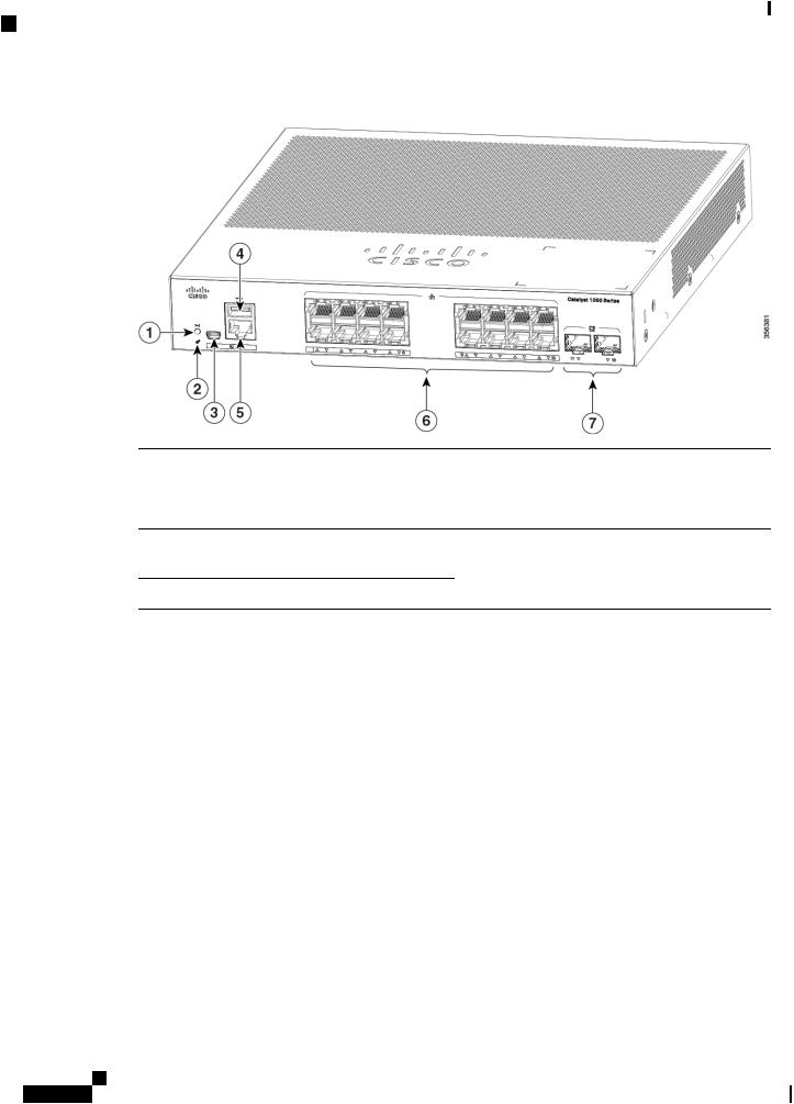
Figure 1: Front Panel of an 8-Port Cisco Catalyst C1000 PoE Switch
1 |
Reset button |
5 |
RJ-45 Console Port |
2 |
System LEDs |
6 |
810/100/1000PoE+ports |
3 |
USB mini-Type B |
7 |
Combo ports (2 GE |
|
(console) port |
|
Copper ports and 2 SFP |
4 |
USB Type A port |
|
module ports) |
|
|
Cisco Catalyst 1000 Series 8-Port and 16-Port Switch Hardware Installation Guide
3
Product Overview
PoE Ports
Figure 2: Front Panel of a 16-Port Cisco Catalyst 1000 PoE Switch
1 |
Reset button |
5 |
RJ-45 Console Port |
2 |
System LEDs |
6 |
16 10/100/1000 PoE+ |
|
|
|
ports |
3 |
USB mini-Type B |
7 |
SFP module slots |
|
(console) port |
|
|
4 |
USB Type A port |
|
|
PoE Ports
The ports provide PoE support for devices compliant with IEEE 802.3af and IEEE 802.3at and also provide PoE support for Cisco IP Phones and Cisco Aironet Access Points. The PoE switch ports are Power Source equipment (PSE) capable and source power to PD devices connected to the downlink ports. A switch can source POE power of up to 30.8W per port.
Depending on the switch model and the number of PoE ports, the maximum switch power output varies between 67 W to 740 W. On a per-port basis, you can control whether or not a port automatically provides power when an IP phone or an access point is connected.
The PoE ports use RJ-45 connectors with Ethernet pinouts. The 10BASE-T, 100BASE-TX, 1000BASE-T traffic requires Category 5 or Category 5e twisted pair (UTP) cable. The 10BASE-T traffic can use Category 3 or Category 4 UTP cable.
10/100/1000 Ports
The 10/100/1000 ports use RJ-45 connectors with Ethernet pinouts. The maximum cable length is 328 feet (100 meters). The 10BASE-T, 100BASE-TX, 1000BASE-T traffic requires Category 5 or Category 5e twisted pair (UTP) cable. The 10BASE-T traffic can use Category 3 or Category 4 UTP cable.
Cisco Catalyst 1000 Series 8-Port and 16-Port Switch Hardware Installation Guide
4

Product Overview
Console Ports
Console Ports
The console ports connect the switch to a PC running Microsoft Windows or to a terminal server.
•RJ-45 console port (EIA/TIA-232). The RJ-45 console port connection uses an RJ-45-to-DB-9 female cable.
•USB mini-Type B console port (5-pin connector).
If you use the USB mini-Type B console port, the Cisco Windows USB device driver must be installed on any PC connected to the console port (for operation with Microsoft Windows). Mac OS X or Linux do not require special drivers.
The 4-pin mini-Type B connector resembles the 5-pin mini-Type B connectors. They are not compatible. Use only the 5-pin mini-Type B.
This illustration shows a 5-pin mini-Type B USB port.
Figure 3: USB Mini-Type B Port
With the Cisco Windows USB device driver, you can connect and disconnect the USB cable from the console port without affecting Windows HyperTerminal operations.
The console output always goes to both the RJ-45 and the USB console connectors, but the console input is active on only one of the console connectors at any one time. The USB console takes precedence over the RJ-45 console. When a cable is connected into the USB console port, the RJ-45 console port becomes inactive. Conversely, when the USB cable is disconnected from the USB console port, the RJ-45 port becomes active.
You can use the command-line interface (CLI) to configure an inactivity timeout which reactivates the RJ-45 console if the USB console has been activated and no input activity has occurred on the USB console for a specified time.
After the USB console deactivates due to inactivity, you cannot use the CLI to reactivate it. Disconnect and reconnect the USB cable to reactivate the USB console. For information on using the CLI to configure the USB console interface, see the software guide.
SFP Module Slots
The switch has two 1G SFP module slots. The SFP modules provide copper or fiber-optic connections to other devices. These transceiver modules are field replaceable, and provide the uplink interfaces when installed in an SFP module slot. The SFP modules have LC connectors for fiber-optic connections or RJ-45 connectors for copper connections. The SFP slots support only SFP modules.
For Cisco SFP modules documentation, including compatibility matrixes, refer to this URL: http://www.cisco.com/en/US/products/hw/modules/ps5455/products_device_support_tables_list.html
Table 2: Port mapping for Cisco Catalyst 1000 8-Port Switch models
 1-GigabitEthernet ports
GigabitEthernet1/0/9
Cisco Catalyst 1000 Series 8-Port and 16-Port Switch Hardware Installation Guide
5
Product Overview
LEDs
 1-GigabitEthernet ports
GigabitEthernet1/0/10
Table 3: Port mapping for Cisco Catalyst 1000 16-Port Switch models
 1-GigabitEthernet ports
GigabitEthernet1/0/17
GigabitEthernet1/0/18
LEDs
You can use the switch system and port LEDs to monitor switch activity and performance.
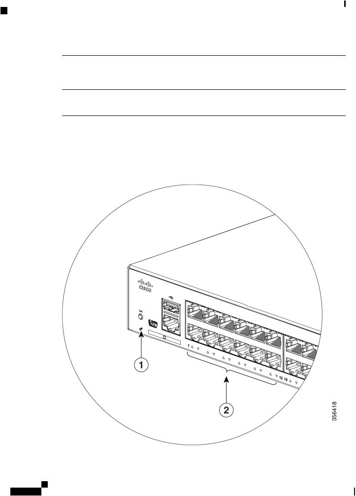
Figure 4: System LED
Cisco Catalyst 1000 Series 8-Port and 16-Port Switch Hardware Installation Guide
6

Product Overview
System LED
1 |
SYST LED (system) |
2 |
Port LEDs |
System LED
Color |
System Status |
Off |
System is not powered on. |
Green |
System is operating normally. |
Amber |
System is receiving power but is not operating |
|
properly. |
Blinking Green |
POST is in progress. |
Port LEDs
Note Physically, there is no amber LED on the device. For all LED-related information of the device, run the show hardware led command in privileged EXEC mode.
RJ-45portsandSFP-moduleslotshaveportLEDs. TheseLEDs,asagrouporindividually,provideinformation about the switch and about the individual ports.
LED Color |
Description |
Off |
No link or port was administratively shut down. |
Green |
Link present. |
Blinking Green |
Activity. Port is sending or receiving data. |
Rear Panel
•A security slot
•An AC power connector
•A loop (for the optional power cord retainer)
•Heat sink fins (PoE models only)
Cisco Catalyst 1000 Series 8-Port and 16-Port Switch Hardware Installation Guide
7

Product Overview
Rear Panel
Figure 5: Rear Panel of a Non-PoE Switch
1 |
Security Slot |
3 |
A loop (for the optional |
|
|
|
power cord retainer) |
2 |
An AC power connector |
|
|
Figure 6: Rear Panel of a PoE Switch
1 |
Security Slot |
3 |
An AC power connector |
2 |
Heat sink fins |
4 |
A loop (for the optional |
|
|
|
power cord retainer) |
Cisco Catalyst 1000 Series 8-Port and 16-Port Switch Hardware Installation Guide
8

Product Overview
Internal Power Supply
Figure 7: Rear Panel of an Externally Powered Switch
1 |
Security Slot |
3 |
A loop (for the optional |
|
|
|
power cord retainer) |
2 |
A DC power connector |
|
|
Internal Power Supply
The internal power supply is an autoranging unit that supports input voltages between 100 and 240 VAC (max of 90V to 264V). The AC frequency range of the power supply is 50Hz/60Hz. Plug the AC power cord into the AC power connector and into an AC power outlet.
Security Slot
The switches have security slots on the rear panel. You can install an optional cable lock, such as the type that is used to secure a laptop computer, to secure the switch.
Cisco Catalyst 1000 Series 8-Port and 16-Port Switch Hardware Installation Guide
9

Product Overview
Network Configurations
Figure 8: Switch Rear Panel
Network Configurations
See the switch software configuration guide for network configuration concepts and examples of using the switch to create dedicated network segments and interconnecting the segments through Fast Ethernet and Gigabit Ethernet connections.
Cisco Catalyst 1000 Series 8-Port and 16-Port Switch Hardware Installation Guide
10
C H A P T E R 2
Switch Installation
This chapter contains these topics:
•Safety Warnings, on page 11
•Box Contents, on page 15
•Tools and Equipment, on page 18
•Installation Guidelines, on page 18
•Verifying Switch Operation, on page 19
•Mounting the Switch, on page 19
•Installing the Power Cord Retainer (Optional), on page 27
•Installing the Cable Guard (Optional), on page 30
•Installing SFP Modules, on page 33
•10/100/1000 PoE and PoE+Port Connections, on page 35
•10/100/1000 Ethernet Port Connections, on page 37
Safety Warnings
Warning To reduce the risk of electric shock, disconnect all power cords before servicing.
Warning The switch is to be connected only to PoE networks without routing to the outside plant.
This section includes the warning statements relating to basic installation. Read this section before you start the installation procedure.
Warning Before working on equipment that is connected to power lines, remove jewelry (including rings, necklaces, and watches). Metal objects will heat up when connected to power and ground and can cause serious burns or weld the metal object to the terminals. Statement 43
Cisco Catalyst 1000 Series 8-Port and 16-Port Switch Hardware Installation Guide
11

Switch Installation
Safety Warnings
Warning Do not stack the chassis on any other equipment. If the chassis falls, it can cause severe bodily injury and equipment damage. Statement 48
Warning Read the wall-mounting instructions carefully before beginning installation. Failure to use the correct hardware or to follow the correct procedures could result in a hazardous situation to people and damage to the system.
Statement 378
Warning Connect USB Device to a Certified USB Port. Statement 388
Warning To avoid or reduce the risk of personal injury, do not use the product if the product has been exposed to irregular environmental conditions, if the product has been misused or if parts of the product have been damaged. Consult qualified service personnel. Never try to service the product yourself. Statement 0416
Warning To reduce the risk of electric shock, fire or personal injury, do not place power cables in areas where they may be walked on or damaged by items placed upon or against it. Statement 0417
Warning This product is intended for use in a normal environment based on the standard IEC60950-1 and IEC62368-1. Do not use the product in vehicles, on board ships, in aircrafts or in medical applications with physical connection to the patient, nor in environments with exposure to moisture, dust, vibration or ingress of water.
Statement 0418
Warning Equipment is intended for installation in Information Technology Equipment Rooms. Suitable for installation in Information Technology Rooms in accordance with Article 645 of the National ElectricalCode and NFPA 75. Statement 0444
Warning Do not work on the system or connect or disconnect cables during periods of lightning activity. Statement
1001
Warning Read the installation instructions before connecting the system to the power source. Statement 1004
Cisco Catalyst 1000 Series 8-Port and 16-Port Switch Hardware Installation Guide
12

Switch Installation
Safety Warnings
Warning Class 1 laser product. Statement 1008
Warning There is the danger of explosion if the battery is replaced incorrectly. Replace the battery only with the same orequivalenttyperecommendedbythemanufacturer. Disposeofusedbatteriesaccordingtothemanufacturer’s instructions. Statement 1015
Warning This unit is intended for installation in restricted access areas. A restricted access area can be accessed only through the use of a special tool, lock and key, or other means of security. Statement 1017
Warning Take care when connecting units to the supply circuit so that wiring is not overloaded. Statement 1018
Warning The plug-socket combination must be accessible at all times, because it serves as the main disconnecting device. Statement 1019
Warning Thisequipmentmustbegrounded. Neverdefeatthegroundconductororoperatetheequipmentintheabsence of a suitably installed ground conductor. Contact the appropriate electrical inspection authority or an electrician if you are uncertain that suitable grounding is available. Statement 1024
Warning Class 1 LED product. Statement 1027
Warning Only trained and qualified personnel should be allowed to install, replace, or service this equipment. Statement
1030
Warning Ultimate disposal of this product should be handled according to all national laws and regulations. Statement
1040
Warning When installing or replacing the unit, the ground connection must always be made first and disconnected last.
Statement 1046
Cisco Catalyst 1000 Series 8-Port and 16-Port Switch Hardware Installation Guide
13
Loading...