


 Loading...
Cisco ASR 901 10G Series Aggregation
Services Router Hardware Installation
Guide
November, 2014
Cisco Systems, Inc.
www.cisco.com
Cisco has more than 200 offices worldwide. Addresses, phone numbers, and fax numbers are listed on the Cisco website at www.cisco.com/go/offices.
Text Part Number: OL-28105-02
THE SPECIFICATIONS AND INFORMATION REGARDING THE PRODUCTS IN THIS MANUAL ARE SUBJECT TO CHANGE WITHOUT NOTICE. ALL STATEMENTS, INFORMATION, AND RECOMMENDATIONS IN THIS MANUAL ARE BELIEVED TO BE ACCURATE BUT ARE PRESENTED WITHOUT WARRANTY OF ANY KIND, EXPRESS OR IMPLIED. USERS MUST TAKE FULL RESPONSIBILITY FOR THEIR APPLICATION OF ANY PRODUCTS.
THE SOFTWARE LICENSE AND LIMITED WARRANTY FOR THE ACCOMPANYING PRODUCT ARE SET FORTH IN THE INFORMATION PACKET THAT SHIPPED WITH THE PRODUCT AND ARE INCORPORATED HEREIN BY THIS REFERENCE. IF YOU ARE UNABLE TO LOCATE THE SOFTWARE LICENSE OR LIMITED WARRANTY, CONTACT YOUR CISCO REPRESENTATIVE FOR A COPY.
The Cisco implementation of TCP header compression is an adaptation of a program developed by the University of California, Berkeley (UCB) as part of UCB’s public domain version of the UNIX operating system. All rights reserved. Copyright © 1981, Regents of the University of California.
NOTWITHSTANDING ANY OTHER WARRANTY HEREIN, ALL DOCUMENT FILES AND SOFTWARE OF THESE SUPPLIERS ARE PROVIDED “AS IS” WITH ALL FAULTS. CISCO AND THE ABOVE-NAMED SUPPLIERS DISCLAIM ALL WARRANTIES, EXPRESSED OR IMPLIED, INCLUDING, WITHOUT LIMITATION, THOSE OF MERCHANTABILITY, FITNESS FOR A PARTICULAR PURPOSE AND NONINFRINGEMENT OR ARISING FROM A COURSE OF DEALING, USAGE, OR TRADE PRACTICE.
IN NO EVENT SHALL CISCO OR ITS SUPPLIERS BE LIABLE FOR ANY INDIRECT, SPECIAL, CONSEQUENTIAL, OR INCIDENTAL DAMAGES, INCLUDING, WITHOUT LIMITATION, LOST PROFITS OR LOSS OR DAMAGE TO DATA ARISING OUT OF THE USE OR INABILITY TO USE THIS MANUAL, EVEN IF CISCO OR ITS SUPPLIERS HAVE BEEN ADVISED OF THE POSSIBILITY OF SUCH DAMAGES. OR LIMITED WARRANTY, CONTACT YOUR CISCO REPRESENTATIVE FOR A COPY.
Cisco and the Cisco logo are trademarks or registered trademarks of Cisco and/or its affiliates in the U.S. and other countries. To view a list of Cisco trademarks, go to this URL: www.cisco.com/go/trademarks. Third-party trademarks mentioned are the property of their respective owners. The use of the word partner does not imply a partnership relationship between Cisco and any other company. (1110R)
Cisco ASR 901 10G Series Aggregation Services Router Hardware Installation Guide
Copyright © 2012, 2014 Cisco Systems, Inc.

C O N T E N T S
|
About This Guide |
vii |
|
|
|
Document Revision History vii |
|||
|
Objectives |
viii |
|
|
|
Audience |
viii |
|
|
|
Organization |
viii |
|
|
|
Conventions |
viii |
|
|
|
Safety Warnings ix |
|
||
|
Related Documentation |
ix |
||
|
Obtaining Documentation, Obtaining Support, and Security Guidelines x |
|||
|
Introduction |
|
|
|
C H A P T E R 1 |
1-1 |
|
|
|
|
Hardware Description |
1-1 |
||
|
Cisco ASR 901 10G Router—Front View of TDM Version 1-2 |
|||
|
Cisco ASR 901 10G Router—Front View of Ethernet Version 1-3 |
|||
|
Cisco ASR 901 10G Router—Rear View 1-4 |
|||
|
LEDs |
1-5 |
|
|
|
Power Supply |
1-5 |
|
|
|
|
Safety Precautions |
1-5 |
|
|
|
|
Environmental Monitoring Temperature Sensor |
1-7 |
|||
|
System Specifications |
1-7 |
|
|
|
|
Router Interface Numbering |
1-7 |
|
||
|
Cisco ASR 901 10G Router 1-8 |
|
|||
|
Regulatory Compliance |
1-9 |
|
|
|
|
Preparing to Install the Router |
|
|
||
C H A P T E R 2 |
2-1 |
|
|||
|
Safety Guidelines 2-1 |
|
|
|
|
|
Safety with Equipment |
2-1 |
|
||
|
Safety with Electricity |
2-2 |
|
||
|
Preventing Electrostatic Discharge Damage |
2-3 |
|||
|
Prerequisites |
2-4 |
|
|
|
|
Site Planning |
2-4 |
|
|
|
|
Power Supply Considerations |
2-4 |
|
|
|
|
Cisco ASR 901 10G Series Aggregation Services Router Hardware Installation Guide |
|
|
|
|
|
|||||
|
|
|
|
|
|
|
OL-28105-02 |
|
|
iii |
|
|
|
|
|
||

Contents
Site Environment 2-4 |
|
Air Flow Guidelines |
2-5 |
Method of Procedure |
2-5 |
Unpacking and Checking the Contents of your Shipment 2-6 |
|
Required Tools and Equipment 2-6 |
|
Installation Checklist |
2-7 |
Creating a Site Log |
2-8 |
|
|
|
|
|
Console Port Considerations |
2-8 |
|
|
|
|
|
|
|
|
|
|
|
|
Console Port Connections |
2-8 |
|
|
|
|
|
||
|
|
Installing the Cisco ASR 901 10G Router |
|
|
|
|
|||||||
C H A P T E R 3 |
|
3-1 |
|
|
|
||||||||
|
|
|
|
|
Network Modules |
3-1 |
|
|
|
|
|
|
|
|
|
|
|
|
Mounting the Cisco ASR 901 10G Router |
3-2 |
|
|
|
||||
|
|
|
|
|
Rack-Mounting Configuration Guidelines |
3-2 |
|
|
|||||
|
|
|
|
|
Attaching Brackets to the Router |
3-3 |
|
|
|
||||
|
|
|
|
|
Mounting the Cisco ASR 901 10G Router in a Rack |
3-7 |
|
||||||
|
|
|
|
|
Wall-Mounting 3-7 |
|
|
|
|
|
|
|
|
|
|
|
|
|
Attaching Brackets for Wall-Mounting |
3-8 |
|
|
|||||
|
|
|
|
|
Mounting the Router on a Wall |
3-9 |
|
|
|
||||
|
|
|
|
|
Connecting the Chassis Ground and Power |
3-10 |
|
|
|||||
|
|
|
|
|
Grounding the Cisco ASR 901 10G Router |
3-10 |
|
|
|||||
|
|
|
|
|
Power Connection Compliance |
3-12 |
|
|
|
|
|||
|
|
|
|
|
Wiring the DC-Input Power Source |
3-12 |
|
|
|
||||
|
|
|
|
|
Installing the DC Power Cord Retainer |
3-13 |
|
|
|||||
|
|
|
|
|
Installing the AC Power Cord Retainer |
3-15 |
|
|
|||||
|
|
|
|
|
Installing and Removing SFP Modules |
3-17 |
|
|
|
||||
|
|
|
|
|
Installing SFP Modules |
3-17 |
|
|
|
|
|
|
|
|
|
|
|
|
Removing SFP Modules |
3-19 |
|
|
|
|
|
|
|
|
|
|
|
|
Connecting Cables |
3-20 |
|
|
|
|
|
|
|
|
|
|
|
|
Connecting the Console Port |
3-20 |
|
|
|
|
|||
|
|
|
|
|
Types of RJ-45 Cables 3-20 |
|
|
|
|
|
|||
|
|
|
|
|
Console Port 3-20 |
|
|
|
|
|
|
|
|
|
|
|
|
|
Connecting the Network Cables |
3-21 |
|
|
|
||||
|
|
|
|
|
Connecting Gigabit Ethernet Interface Cables |
3-21 |
|
||||||
|
|
|
|
|
Connecting T1 and E1 Interface Cables |
3-21 |
|
|
|||||
|
|
|
|
|
Connecting SFP Cables |
3-22 |
|
|
|
|
|
||
|
|
|
|
|
Connecting Cables to the BITS Interface 3-22 |
|
|
||||||
|
|
|
|
|
Connecting GPS Cables |
3-22 |
|
|
|
|
|
||
|
|
|
|
|
Connecting to Alarm Port |
3-23 |
|
|
|
|
|||
|
|
|
|
Cisco ASR 901 10G Series Aggregation Services Router Hardware Installation Guide |
|
|
|||||||
|
|
|
|
|
|
||||||||
|
|
|
|
|
|
|
|
|
|
|
|
|
|
|
iv |
|
|
|
|
|
|
|
|
|
|
OL-28105-02 |
|
|
|
|
|
|
|
|
|
|
|
|
|
||

Contents
|
|
|
Connecting to the Management Ethernet Port |
3-23 |
|
|
|
||||||
|
|
|
Dressing Router Cables |
3-23 |
|
|
|
|
|
|
|
||
|
|
|
Powering on the Router |
3-24 |
|
|
|
|
|
|
|
||
|
|
|
Checklist for Power on |
3-24 |
|
|
|
|
|
|
|
||
|
|
|
Interpreting Front-Panel LEDs |
3-24 |
|
|
|
|
|
||||
|
|
|
Power-On Procedure |
3-24 |
|
|
|
|
|
|
|
||
|
|
|
Formatting Procedures for Flash Memory |
3-25 |
|
|
|
|
|||||
|
|
|
Formatting Flash Memory as a DOS File System 3-25 |
||||||||||
|
|
|
File and Directory Procedures |
3-25 |
|
|
|
|
|
||||
|
|
|
Copying Files |
3-25 |
|
|
|
|
|
|
|
|
|
|
|
|
Displaying Contents of the Flash Memory 3-26 |
||||||||||
|
|
|
Deleting Files from the Flash Memory |
3-26 |
|
|
|
|
|||||
|
|
|
Displaying File Content |
3-27 |
|
|
|
|
|
|
|||
|
|
|
Enter a Directory and Determine the Current Directory 3-27 |
||||||||||
|
|
|
What to Do After Installing the Hardware |
3-28 |
|
|
|
|
|||||
|
|
Troubleshooting A-1 |
|
|
|
|
|
|
|
|
|
||
A P P E N D I X |
A |
|
|
|
|
|
|
|
|
|
|||
|
|
|
Problem Solving |
A-1 |
|
|
|
|
|
|
|
|
|
|
|
|
Troubleshooting the Power and Cooling Systems |
A-2 |
|||||||||
|
|
|
Environmental Reporting Features |
A-2 |
|
|
|
|
|
||||
|
|
|
Troubleshooting Cables and Connections |
A-3 |
|
|
|
|
|||||
|
|
|
Reading the LEDs |
A-3 |
|
|
|
|
|
|
|
|
|
|
|
|
Chassis LEDs |
A-4 |
|
|
|
|
|
|
|
|
|
|
|
|
T1/E1 Interface LEDs |
A-5 |
|
|
|
|
|
|
|||
|
|
|
SFP Ethernet Interface LEDs |
A-5 |
|
|
|
|
|
||||
|
|
|
10G SFP+ Ethernet Interface LEDs A-5 |
|
|
|
|
||||||
|
|
|
RJ-45 Ethernet Interface LEDs |
A-5 |
|
|
|
|
|
||||
|
|
Cable Specifications |
|
|
|
|
|
|
|
|
|
|
|
A P P E N D I X |
B |
B-1 |
|
|
|
|
|
|
|
|
|
||
|
|
|
Gigabit Ethernet Connector Pinouts |
B-1 |
|
|
|
|
|
||||
|
|
|
SFP and SFP+ Port Pinouts and Cable Specifications |
B-2 |
|||||||||
|
|
|
T1/E1 Port Pinouts |
B-2 |
|
|
|
|
|
|
|
|
|
|
|
|
Console Port Signals and Pinouts |
B-3 |
|
|
|
|
|
|
|||
|
|
|
Console Port Signals and Pinouts |
B-4 |
|
|
|
|
|
||||
|
|
|
Identifying a Rollover Cable |
B-5 |
|
|
|
|
|
||||
|
|
|
BITS Port Pinouts |
B-6 |
|
|
|
|
|
|
|
|
|
|
|
|
Time of Day Pinouts B-6 |
|
|
|
|
|
|
|
|
||
|
|
|
GPS Port Pinouts |
B-7 |
|
|
|
|
|
|
|
|
|
|
|
|
|
Cisco ASR 901 10G Series Aggregation Services Router Hardware Installation Guide |
|
|
|
||||||
|
|
|
|
|
|||||||||
|
|
|
|
|
|
|
|
|
|
|
|
|
|
|
OL-28105-02 |
|
|
|
|
|
|
|
|
|
v |
|
|
|
|
|
|
|
|
|
|
|
|
|
|||

Contents
|
Alarm Port Pinouts B-8 |
|
Management Ethernet Port Pinouts B-8 |
|
Site Log C-1 |
A P P E N D I X C |
|
|
|
I N D E X |
|
Cisco ASR 901 10G Series Aggregation Services Router Hardware Installation Guide
|
vi |
OL-28105-02 |
|
|
|
About This Guide
This section describes the objectives, audience, organization, and conventions of this hardware installation guide.
Note Use this document with the documents listed in the “Related Documentation” section on page 3.
This section contains the following topics:
•Document Revision History, page 1
•Objectives, page 2
•Audience, page 2
•Organization, page 2
•Conventions, page 2
•Safety Warnings, page 3
•Related Documentation, page 3
•Obtaining Documentation, Obtaining Support, and Security Guidelines, page 4
Document Revision History
The Document Revision History table below records technical changes to this guide. The table shows the document revision number for the change, the date of the change, and a brief summary of the change. Not all Cisco documents use a Document Revision History table.
Revision |
Date |
Change Summary |
|
|
|
OL-28105-01 |
October 2012 |
Initial version of the document. |
|
|
|
OL-28105-02 |
March 2014 |
Added information on new variants of the router. |
|
|
|
Cisco ASR 901 10G Series Aggregation Services Router Hardware Installation Guide
|
OL-28105-02 |
1 |
|
|
|

Objectives
This guide explains how to install, maintain, and troubleshoot your router hardware.
It provides the minimum software configuration information. For the detailed configuration procedures, see the Cisco IOS configuration guide and command reference publications. For more information, see the “Obtaining Documentation, Obtaining Support, and Security Guidelines” section on page 4.
Warranty, service, and support information is in the Cisco Information Packet that is shipped with your router.
Audience
This guide is designed for personnel who install, configure, and maintain the router. These persons should be familiar with electronic circuitry and wiring practices and be experienced electronic or electromechanical technicians. This guide identifies certain procedures that should be performed only by trained and qualified personnel.
Organization
Chapter |
Title |
Description |
|
|
|
Chapter 1 |
Introduction |
Describes the hardware features and specifications of |
|
|
the routers. |
|
|
|
Chapter 2 |
Preparing to Install the Router |
Describes safety recommendations, site requirements, |
|
|
network connection considerations, required tools and |
|
|
equipment, and provides the installation checklist. |
|
|
|
Chapter 3 |
Installing the |
Includes router installation information, and shows |
|
Cisco ASR 901 10G Router |
how to connect the router console port. |
|
|
|
Appendix A |
Troubleshooting |
Describes how to isolate problems, read LEDs, |
|
|
interpret error and status messages, and recover |
|
|
software images. |
|
|
|
Appendix B |
Cable Specifications |
Provides cable specifications to use if you plan to build |
|
|
your own cables. |
|
|
|
Appendix C |
Site Log |
Provides example site log. |
|
|
|
Conventions
Note Means reader take note.
Tip Means the following information will help you solve a problem.
Cisco ASR 901 10G Series Aggregation Services Router Hardware Installation Guide
2 |
OL-28105-02 |
|
|
Caution Means reader be careful. In this situation, you might perform an action that could result in equipment damage or loss of data.
Safety Warnings
Safety warnings appear throughout this publication in procedures that, if performed incorrectly, might harm you. A warning symbol precedes each warning statement. The safety warnings provide safety guidelines that you should follow when working with any equipment that connects to electrical power or telephone wiring. Warnings are translated into several languages. (For information about compliance guidelines and translated safety warnings, refer to Cisco Regulatory Compliance and Safety Information for the Cisco ASR 901 Router.
Warning IMPORTANT SAFETY INSTRUCTIONS
This warning symbol means danger. You are in a situation that could cause bodily injury. Before you work on any equipment, be aware of the hazards involved with electrical circuitry and be familiar with standard practices for preventing accidents. Use the statement number provided at the end of each warning to locate its translation in the translated safety warnings that accompanied this device. Statement 1071
SAVE THESE INSTRUCTIONS
Related Documentation
For additional information, refer to the following documents:
•Cisco Regulatory Compliance and Safety Information for Cisco ASR 901 Series Aggregation Services Router
•Cisco ASR 901 Series Aggregation Services Router Software Configuration Guide
•Cisco ASR 901 Series Aggregation Services Router Command Reference
•Release Notes for Cisco ASR 901 Series Aggregation Services Router
To access the related documentation on Cisco.com, go to:
http://www.cisco.com/c/en/us/support/routers/asr-901-10g-series-aggregation-services-routers/tsd-pro ducts-support-series-home.html
Cisco ASR 901 10G Series Aggregation Services Router Hardware Installation Guide
|
OL-28105-02 |
3 |
|
|
|

Obtaining Documentation, Obtaining Support, and Security
Guidelines
For information on obtaining documentation, obtaining support, providing documentation feedback, security guidelines, and also recommended aliases and general Cisco documents, see the monthly What’s New in Cisco Product Documentation, which also lists all new and revised Cisco technical documentation, at:
http://www.cisco.com/en/US/docs/general/whatsnew/whatsnew.html
Cisco ASR 901 10G Series Aggregation Services Router Hardware Installation Guide
4 |
OL-28105-02 |
|
|
C H A P T E R 1
Introduction
The Cisco ASR 901 10G router is a cell site gateway platform specifically designed to provide transport for both legacy TDM and Ethernet traffic over a single converged network. The Cisco ASR 901 10G router is used at the cell site as a part of a 2G, 3G, or 4G radio access network (RAN) traffic. This router is a small form factor, fixed, low cost platform/solution that seeks to complement the current Cisco portfolio in the IP-RAN segment.
This chapter includes the following sections:
•Hardware Description, page 1-1
•Power Supply, page 1-5
•System Specifications, page 1-9
•Router Interface Numbering, page 1-9
•Regulatory Compliance, page 1-11
Hardware Description
Note This equipment is suitable for installation in Network Telecommunications Facilities and locations where the NEC applies. The equipment is suitable for installation as part of the Common Bonding Network (CBN).
Contained in a standard shelf-rack enclosure, the Cisco ASR 901 10G router weighs approximately 10 pounds (4 kg). It measures 1.7 inches high x 17.5 inches wide x 9.1 inches deep (43.2 x 444.5 x 231 mm), 1RU. These dimensions do not include the rack-mount brackets.
You can mount the router in a standard (ETSI) 19-inch (48.3 cm) equipment rack or 600mm ETSI rack or a 23-inch ETSI rack.
The Cisco ASR 901 10G router includes the following hardware features:
•Eight T1/E1 RJ45 ports.
•Four ports of 100/1000 Copper Ethernet including auto-MDIX (RJ45 connector)
•Four ports of SFP only
•Two ports of 10G SFP+ only
•Four combo ports (SFP/Copper)
Cisco ASR 901 10G Series Aggregation Services Router Hardware Installation Guide
|
OL-28105-02 |
1-1 |
|
|
|

Chapter 1 |
Introduction |
Hardware Description
•Dual feed supply with redundant DC inputs plus built in redundant power supply (RPS) or single AC input.
•Three fans placed in the chassis
•Chassis: I RU, 10 inch depth (Cisco ASR 901 10G router)
•Operating temperature range is -40 to +149°F (-40°C to +65°C).
•Airflow is left to right
•Four solid state alarm inputs
•A single built-in 1Gigabit (128 MB) Flash memory. For A901-6CZ-FS-D and A901-6CZ-FS-A PIDs, the memory requirement is 256MB.
•Two management ports: RS-232 serial console and 10/100 Base-T Ethernet ports
•One BITS clock port (RJ45) and 1 ToD port (RJ45)
•Two miniature coaxial connectors for 10Mhz and 1PPS timing (input or output). You can use these interfaces with an external GPS device to send or receive clocking from the router.
•A single USB port
•Two LEDs for each T1/E1 port
–C—indicates out of service or not configured, carrier condition, and loop condition
–AL—no alarm, or alarm condition
•Two LEDs for each Ethernet port
–L—indicates activity, lack of activity, or no link
–S—indicates speed (100 or 1000) or off
•One System LED:
–Solid Green—System Healthy (normal operation)
–Solid RED—System Faulty
Cisco ASR 901 10G Router—Front View of TDM Version
The front panel of the Cisco ASR 901 10G (TDM version) router has the following components:
•Eight T1/E1 ports, labelled T1/E1 (positions 0, 1, 2, 3, 4, 5, 6, and 7)
•Eight RJ-45 connectors for copper Ethernet ports, labeled “GE” (positions 0, 1, 2, 3, 4, 5, 6, and 7)
•Eight SFP connectors for optical GE ports (positions 4, 5, 6, 7, 8, 9, 10, and 11)
•Two SFP+ connectors for optical 10 G ports (positions 0 and 1)
•Two miniature coaxial connectors for 10MHZ and 1PPS timing
•A single RJ-45 connector for console, labeled “CONSOLE”
•A single RJ-45 connector for management port, labeled “MGMNT”
•A single RJ-45 connector for the BITS interface, labeled “BITS”
•A single RJ-45 connector for the ToD interface, labeled “TOD”
•A single RJ-45 connector for alarm.
•Dual feed supply with redundant DC inputs or single AC input.
•The following LEDs
Cisco ASR 901 10G Series Aggregation Services Router Hardware Installation Guide
1-2 |
OL-28105-02 |
|
|
Chapter 1 Introduction
Hardware Description
–T1/E1 ports
–Ethernet ports
–SFP ports
–Chassis: Single LED for multiple conditions
Figure 1-1 shows the front view of the Cisco ASR 901 10G router (TDM version) with each interface module.
Figure 1-1 |
Cisco ASR 901 10G Router—Front View of TDM Version |
11
7 5
14 |
|
|
9 |
|
|
|
|
13 |
12 |
10 |
|
|
|
|
|
|
8 |
6 |
|
|
|
||
|
|
4 |
|
|
|||
|
|
|
|
|
|||
|
|
|
|
|
|
|
|
|
|
|
|
|
3 |
2 |
1 |
|
|
|
|
|
|
||
|
|
|
|
|
|
|
334524
1 |
Power LED |
8 |
BITS port |
|
|
|
|
|
|
2 |
10G SFP+ |
9 |
MINI-coax connector (10MHZ) |
|
|
|
|
|
|
3 |
8 |
SFP ports |
10 |
MINI-coax connector (1PPS) |
|
|
|
|
|
4 |
8 |
GE port |
11 |
USB port |
|
|
|
|
|
5 |
Management port |
12 |
Alarm |
|
|
|
|
|
|
6 |
Console port |
13 |
8 T1/E1 ports |
|
|
|
|
|
|
7 |
ToD port |
14 |
Power connector (DC or AC) |
|
|
|
|
|
|
Cisco ASR 901 10G Router—Front View of Ethernet Version
The front panel of the Cisco ASR 901 10G (Ethernet version) router has the following components:
•Two SFP+ connectors for optical 10G ports (positions 0 and 1)
•Eight SFP connectors for optical GE ports (positions 4, 5, 6, 7, 8, 9, 10, and 11)
•Eight RJ-45 connectors for copper Ethernet ports, labeled “GE” (positions 0, 1, 2, 3, 4, 5, 6, and 7)
•A single RJ-45 connector for management port, labeled “MGMT”
•A single RJ-45 connector for console, labeled “CONSOLE”
•A single RJ-45 jack for the BITS interface, labeled “BITS”
•A single RJ-45 jack for the ToD interface, labeled “ToD”
Cisco ASR 901 10G Series Aggregation Services Router Hardware Installation Guide
|
OL-28105-02 |
1-3 |
|
|
|

Chapter 1 |
Introduction |
Hardware Description
•Two miniature coaxial connectors for 10MHZ and 1PPS timing
•A single alarm port
•A single USB port (for AC version)
•Dual feed supply with redundant DC inputs or single AC input. The following LEDs
–Ethernet ports
–SFP ports
–Chassis: Single LED for multiple conditions
Figure 1-2 shows the front view of the Cisco ASR 901 10G router (Ethernet version) with each interface module.
Figure 1-2 Cisco ASR 901 Router—Front View of Ethernet Version
11
7 5
13
12 |
10 |
9 |
8 |
6 |
|
|
|
4 |
|||
|
|
|
|||
|
|
|
|
|
3 2 1
334571
1 |
Power LED |
8 |
BITS port |
|
|
|
|
|
|
2 |
10G SFP+ ports |
9 |
MINI-coax connector (10MHZ) |
|
|
|
|
|
|
3 |
8 |
SFP ports |
10 |
MINI-coax connector (1PPS) |
|
|
|
|
|
4 |
8 |
GE ports |
11 |
USB port |
|
|
|
|
|
5 |
Management port |
12 |
Alarm |
|
|
|
|
|
|
6 |
Console port |
13 |
Power connector (AC or DC) |
|
|
|
|
|
|
7 |
ToD port |
14 |
— |
|
|
|
|
|
|
Cisco ASR 901 10G Router—Rear View
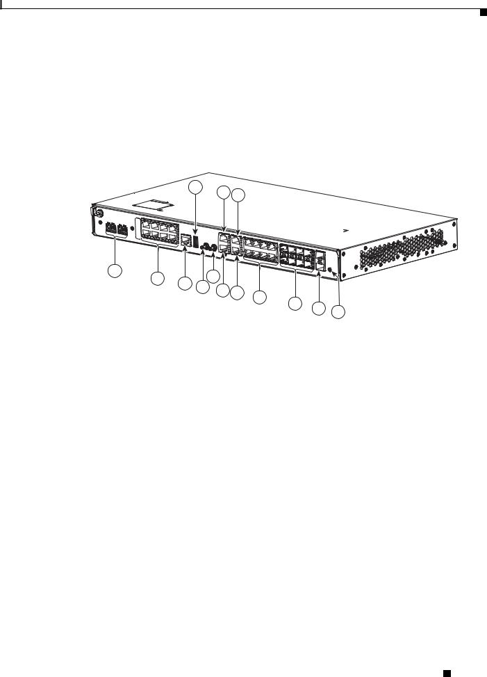
Figure 1-3 shows the rear view of the Cisco ASR 901 10G router, including the orientation of the following components:
•Three blowing fans
•Mounting point for the 2-hole lug. For more information, see the Connecting the Chassis Ground and Power, page 3-10
Cisco ASR 901 10G Series Aggregation Services Router Hardware Installation Guide
1-4 |
OL-28105-02 |
|
|

Chapter 1 Introduction
Figure 1-3 |
Cisco ASR 901 10G Router—Rear View |
2 |
1 |
Power Supply
334636
1 |
Fan |
2 |
Grounding Point Lug |
|
|
|
|
Note The grounding architecture of this product is DC-isolated (DC-I) for DC-powered products. DC-powered products have a nominal operating DC voltage of 48 VDC. Minimal steady state DC operating voltage is 19.2 VDC.
LEDs
The Cisco ASR 901 10G chassis and interface modules contain LEDs to assist in troubleshooting. For more detailed description of the LEDs, see the “Reading the LEDs, page A-4.
Power Supply
The Cisco ASR 901 10G router is equipped with an internal -24/-60 Volts Direct Current (VDC). The router is provided with a single AC power supply or DC (1+1 Redundant) power supply. The power input connectors are located at the front left-side side of the router. The DC power connector has the standard A and B feeds for DC redundancy. The DC power supply is compatible with the range of DC input voltages specifically available at cell sites.
See Table 1-1 for the DC power supply specifications and Table 1-2 for the AC power supply specifications.
Safety Precautions
Observe the following general safety precautions and recommendations in planning the source power requirements for the Cisco ASR 901 10G router (for additional safety information, see the “Safety Guidelines” section on page 2-1:
•Check the power at your site before router installation (and periodically after installation) to ensure clean power (free of spikes and noise) is being received.
•Always disconnect the power source and unplug the power cable before working on the router.
Cisco ASR 901 10G Series Aggregation Services Router Hardware Installation Guide
|
OL-28105-02 |
1-5 |
|
|
|

Chapter 1 |
Introduction |
Power Supply
• Install proper grounding for the site to avoid damage from lightning and power surges.
Warning To avoid electric shock, do not connect safety extra-low voltage (SELV) circuits to telephone-network voltage (TNV) circuits. LAN ports contain SELV circuits, and WAN ports contain TNV circuits. Some LAN and WAN ports both use RJ-45 connectors. Use caution when connecting cables. Statement 1021
Warning There is the danger of explosion if the battery is replaced incorrectly. Replace the battery only with the same or equivalent type recommended by the manufacturer. Dispose of used batteries according to the manufacturer’s instructions. Statement 1015
Warning This unit might have more than one power supply connection. All connections must be removed to de-energize the unit. Statement 1028
Warning The intrabuilding ports of the equipment or subassembly MUST NOT be metallically connected to interfaces that connect to the OSP or its wiring. These interfaces are designed for use only as intrabuilding interfaces (Type 2 or Type 4 ports as described in GR-1089-CORE), and require isolation from the exposed OSP cabling. The addition of primary protectors is not sufficient protection in order to connect these interfaces metallically to OSP wiring.
Warning To comply with the Telcordia GR-1089 NEBS standard for electromagnetic compatibility and safety, connect the (Management Ethernet) ports only to intra-building or unexposed wiring or cable. The intrabuilding cable must be shielded and the shield must be grounded at both ends. The intra-building port(s) of the equipment or subassembly must not be metallically connected to interfaces that connect to the OSP or its wiring. These interfaces are designed for use as intra-building interfaces only (Type 2 or Type 4 ports as described in GR-1089-CORE) and require isolation from the exposed OSP cabling. The addition of Primary Protectors is not sufficient protection in order to connect these interfaces metallically to OSP wiring.
Table 1-1 lists the DC power supply specifications for the Cisco ASR 901 10G router.
Table 1-1 |
Cisco ASR 901 10G Router DC Power Supply Specifications |
||
|
|
|
|
Specification |
|
Value |
|
|
|
||
DC power supply input voltage |
-24/-60 VDC |
||
|
|
|
|
Maximum input current |
4A |
|
|
|
|
||
Wire gauge for DC input power connections |
16 AWG |
||
|
|
|
|
Power dissipation |
• |
A901-6CZ-F-D: 58W |
|
|
|
• |
A901-6CZ-FS-D: 59W |
|
|
• |
A901-6CZ-FT-D: 67W |
|
|
|
|
Table 1-2 lists the AC power supply specifications for the Cisco ASR 901 10G router.
Cisco ASR 901 10G Series Aggregation Services Router Hardware Installation Guide
1-6 |
OL-28105-02 |
|
|
Chapter 1 Introduction
Power Supply
Warning This product requires surge protection as part of the building installation. To comply with the Telcordia GR-1089 NEBS standard for electromagnetic compatibility and safety, an external surge protective device (SPD) is required at the AC power service equipment.
Table 1-2 |
Cisco ASR 901 10G Router AC Power Supply Specifications |
||
|
|
|
|
Specification |
|
Value |
|
|
|
|
|
Power supply |
|
115 to 230 V |
|
|
|
|
|
Power dissipation |
• |
A901-6CZ-F-A: 57W |
|
|
|
• |
A901-6CZ-FS-A: 58W |
|
|
• |
A901-6CZ-FT-A: 65W |
|
|
||
Input voltage rating |
100V-240V, 1A-0.5A, 50-60Hz |
||
|
|
||
Operating voltage rating |
85~264 VAC at 47/63Hz |
||
|
|
||
AC current rating |
1A at 100 VAC and 60 Hz. |
||
|
|
|
|
The Cisco ASR 901 10G router uses two 3-pin connectors (part number 27-1892-01) for DC input to the power supply. The terminal block is part of the accessory kit (part number 53-3438-01), which ships with the Cisco ASR 901 10G router.
The Cisco ASR 901 10G router uses a single 3-pin connector (29-1609-01) for AC input to the power supply.
The ground wire connects to a 2-hole lug, which connects to the corresponding mounting point. With the connector installed in the chassis, the pins numbered from left to right are 1, 3, and 2, respectively.
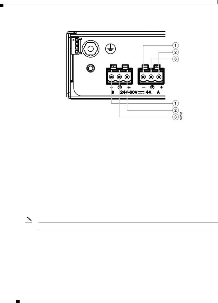
Figure 1-4 shows the pinout configurations for the connector, based on the power source.
Note You can use connector A or B or both.
Cisco ASR 901 10G Series Aggregation Services Router Hardware Installation Guide
|
OL-28105-02 |
1-7 |
|
|
|
Chapter 1 |
Introduction |
Environmental Monitoring Temperature Sensor
Figure 1-4 Power Supply Connector Pinouts
Table 1-3 Power Supply Connector Pinouts (-24/-60 VDC Application)
Pin |
Connector A |
Connector B |
|
|
|
1 |
VDC (-24 to -60) |
VDC (-24 to -60) |
|
|
|
2 |
RTN |
RTN |
|
|
|
3 |
Chassis Ground |
Chassis Ground |
|
|
|
Environmental Monitoring Temperature Sensor
The Cisco ASR 901 10G router has a temperature sensor to detect overtemperature conditions inside the chassis. The overtemperature detection trips at 70°C. This condition is reported to the processor as an interrupt, where the software generates the appropriate alarms. If the router reaches a temperature of 90°C, the power supply cycles itself to prevent the router from exceeding the maximum temperature while being powered up.
Note Auxiliary port is not supported.
Cisco ASR 901 10G Series Aggregation Services Router Hardware Installation Guide
1-8 |
OL-28105-02 |
|
|

Chapter 1 Introduction
System Specifications
System Specifications
Table 1-4 lists the system specifications for the Cisco ASR 901 10G router.
Table 1-4 |
Cisco ASR 901 10G Router System Specifications |
|
|
|
|
Description |
|
Specification |
|
|
|
Dimensions (H x W x D) |
1.7 x 17.5 x 9.1 in. (43.2 x 444.5 x 231 mm) 1 RU (rack unit) in a |
|
|
|
19-inch (48.3 cm) rack |
|
|
|
Weight |
|
• A901-6CZ-FT-D: 8.15 lb (3.7 kg) |
|
|
• A901-6CZ-F-D: 7.93 lb (3.6 kg) |
|
|
• A901-6CZ-FS-D: 7.93 lb (3.6 kg) |
|
|
• A901-6CZ-FT-A: 8.15 lb (3.7 kg) |
|
|
• A901-6CZ-F-A: 7.93 lb (3.6 kg) |
|
|
• A901-6CZ-FS-A: 7.93 lb (3.6 kg) |
|
|
|
Console port |
|
RJ-45 connector |
|
|
|
Operating Temperature |
Operating temperature range is -40°C to +65°C (-40 to +149°F) |
|
|
|
|
Non-Operational Temperature |
Temperature: -40°C to +70°C (-40 to +158°F) |
|
|
|
|
Operating Humidity |
5% to 85%, noncondensing RH, ±5% |
|
|
|
|
Non-Operational Humidity |
Upto 93% RH |
|
|
|
|
Operating Altitude |
13,000 ft. (4000 m) with maximum 104°F (40°C) ambient |
|
|
|
temperature |
|
|
|
Operating Vibration |
0.15 G, 10 to 500 Hz/100 minutes per axis |
|
|
|
|
Non-Operational Vibration |
0.8 G, 10 to 500 Hz/30 minutes per axis |
|
|
|
|
Operating Acoustics |
61 dBA with 19 cfm fan |
|
|
|
|
Air Flow |
|
Left to right, 57 cfm |
|
|
|
Router Interface Numbering
The following section explains router interface numbering and interface labels for the Cisco ASR 901 10G router.
Cisco ASR 901 10G Series Aggregation Services Router Hardware Installation Guide
|
OL-28105-02 |
1-9 |
|
|
|

Chapter 1 |
Introduction |
Router Interface Numbering
Cisco ASR 901 10G Router
Each network interface on a Cisco ASR 901 10G 10G router is identified by a slot number and a port number, explained in this sequence:
•Logical slot numbers starts from 0 for all built-in interfaces. The numbering format is Interface type Slot number/Interface number. Interface (port) numbers begin at logical 0 for each interface type.
•Logical interface numbering for 10G SFP+ ports runs from 0/0 through 0/1. Ports are numbered bottom to top.
•Logical interface numbering for T1/E1 ports on the TDM interface module runs from 0/0 through 0/7. Ports are numbered bottom to top, left to right.
•Logical interface numbering for the built-in ethernet ports runs from g0/0 through g0/3, the combo ports run from g0/4 to g0/7 and the SFP ports run from g0/8 through g0/11. The GE ports are numbered bottom to top, left to right.
Figure 1-5 |
Cisco ASR 901 10G Router Port Numbers |
1
2
3
13
12
10
11
9
8
7
6

 334515
5
4
1 |
ToD port |
7 |
BITS port |
|
|
|
|
2 |
Management port |
8 |
MINI-Coax Connector (1PPS) |
|
|
|
|
3 |
8 GE ports |
9 |
MINI-Coax Connector (10MHZ) |
|
|
|
|
|
Cisco ASR 901 10G Series Aggregation Services Router Hardware Installation Guide |
1-10 |
OL-28105-02 |
Chapter 1 Introduction
|
|
|
Regulatory Compliance |
|
|
|
|
|
|
4 |
SFP+ port |
10 |
USB port |
|
|
|
|
|
|
5 |
8 SFP ports |
11 |
Alarm cable |
|
|
|
|
|
|
6 |
Console port |
12 |
8 T1/E1 ports |
|
|
|
|
|
|
Table 1-5 |
Cisco ASR 901 10G Router Interface Labels |
|
||
|
|
|
|
|
Interface |
|
Number |
Location |
Label |
|
|
|
|
|
SFP connector for optical 10 GE ports |
2 |
Onboard |
10G SFP |
|
|
|
|
|
|
SFP connector for optical GE ports |
8 |
Onboard |
SFP |
|
|
|
|
|
|
RJ45 jacks for copper ethernet ports |
8 |
Onboard |
GE |
|
|
|
|
|
|
RJ45 connector for console |
1 |
Onboard |
CONSOLE |
|
|
|
|
|
|
RJ45 connector for management port |
1 |
Onboard |
MGMNT |
|
|
|
|
|
|
RJ45 jack for BITS interface |
1 |
Onboard |
BITS |
|
|
|
|
|
|
RJ45 jack for Time-of-Day interface |
1 |
Onboard |
TOD |
|
|
|
|
|
|
1PPS mini-coax timing connector |
1 |
Onboard |
1PPS |
|
|
|
|
|
|
10Mhz mini-coax timing connector |
1 |
Onboard |
10MHZ |
|
|
|
|
|
|
RJ48 jacks for T1/E1 ports |
8 |
T1/E1 interface module |
T1/E1 |
|
|
|
|
|
|
RJ48 jacks for Alarm Cable |
1 |
Onboard |
Alarm |
|
|
|
|
|
|
Power connector |
|
1 |
Onboard |
Power Connector |
|
|
|
|
|
Regulatory Compliance
For regulatory compliance and safety information, see Cisco Regulatory Compliance and Safety Information for Cisco ASR 901 Series Aggregation Services Router.
|
|
Cisco ASR 901 10G Series Aggregation Services Router Hardware Installation Guide |
|
|
|
|
|
|
|||
|
OL-28105-02 |
|
|
1-11 |
|
|
|
|
|
||

Chapter 1 |
Introduction |
Regulatory Compliance
|
Cisco ASR 901 10G Series Aggregation Services Router Hardware Installation Guide |
1-12 |
OL-28105-02 |

C H A P T E R 2
Preparing to Install the Router
This chapter describes site requirements and equipment used to install the Cisco ASR 901 10G router. It includes the following sections:
•Safety Guidelines, page 2-1
•Prerequisites, page 2-4
•Site Planning, page 2-4
•Console Port Considerations, page 2-8
Safety Guidelines
Before you begin installing the Cisco ASR 901 10G router, review the safety guidelines in Safety Precautions, page 1-5, and the Rack-Mounting Configuration Guidelines, page 3-2 to avoid injuries to yourself, or damage to the equipment.
Additionally, before replacing, configuring, or maintaining the Cisco ASR 901 10G router, review the safety warnings listed in the document Cisco Regulatory Compliance and Safety Information for Cisco ASR 901 Series Aggregation Services Router.
Safety with Equipment
The following guidelines help ensure your safety and equipment’s protection. This list does not include all the potentially hazardous situations, so be alert.
Warning Before connecting the system to the power source, read the installation instructions. Statement 1004
•Before moving the system, always disconnect all the power cords and interface cables.
•Never assume that power is disconnected from a circuit; always check.
•Before and after installation, keep the chassis area clean and dust-free.
•Keep tools and assembly components away from walk areas to avoid tripping over them.
•Do not work alone in potentially hazardous conditions.
•Do not perform any action that creates a potential hazard to people or makes the equipment unsafe.
•Do not wear loose clothing that may get caught in the chassis.
Cisco ASR 901 10G Series Aggregation Services Router Hardware Installation Guide
|
OL-28105-02 |
2-1 |
|
|
|
Chapter 2 Preparing to Install the Router
Safety Guidelines
• When working under conditions hazardous to your eyes, wear safety glasses.
Safety with Electricity
Warning Before performing any of the following procedures, ensure that power is removed from the DC circuit.
Statement 1003
Warning This unit is intended for installation in restricted access areas. A restricted access area can be accessed only through the use of a special tool, lock and key, or other means of security.
Statement 1017
Warning To avoid electric shock, do not connect safety extra-low voltage (SELV) circuits to telephone-network voltage (TNV) circuits. LAN ports contain SELV circuits, and WAN ports contain TNV circuits. Some LAN and WAN ports both use RJ-45 connectors. Statement 1021
Warning Before working on equipment that is connected to power lines, remove jewelry (including rings, necklaces, and watches). Metal objects will heat up when connected to power and ground and can cause serious burns or weld the metal object to the terminals. Statement 43
Warning Before working on a chassis or working near power supplies, unplug the power cord on AC units; disconnect the power at the circuit breaker on DC units. Statement 12
Warning During periods of lightning activity, do not work on the system or connect or disconnect cables.
Statement 1001
Warning There is the danger of explosion if the battery is replaced incorrectly. Replace the battery only with the same or equivalent type recommended by the manufacturer. Dispose of used batteries according to the manufacturer’s instructions. Statement 1015
Warning This unit might have more than one power supply connection. All connections must be removed to de-energize the unit. Statement 1028
When working on electrical equipment, follow these guidelines:
•Locate the room’s emergency power switch. If an electrical accident occurs, you can quickly switch off the power.
•Before working on the system, switch off the DC main circuit breaker and disconnect the power terminal block cable.
•Disconnect all power before performing the following:
Cisco ASR 901 10G Series Aggregation Services Router Hardware Installation Guide
2-2 |
OL-28105-02 |
|
|

Chapter 2 Preparing to Install the Router
Safety Guidelines
–Working on or near power supplies.
–Installing or removing a router chassis, or network processor module.
–Performing most hardware upgrades.
•Never install equipment that appears damaged.
•Carefully examine your work area for possible hazards, such as wet floors, ungrounded power extension cables, and missing safety grounds.
•Never assume that power is disconnected from a circuit; always check.
•Never perform any action that creates a potential hazard to people or makes the equipment unsafe.
•If an electrical accident occurs, proceed as follows:
–Use caution, and do not become a victim yourself.
–Switch off power to the router.
–If possible, send another person to get medical aid. Otherwise, determine the condition of the victim, and then call for help.
–Determine whether the person needs rescue breathing or external cardiac compressions; then take appropriate action.
In addition, use the following guidelines when working with any equipment that is disconnected from a power source, but still connected to telephone wiring or network cabling:
•Never install telephone wiring during a lightning storm.
•Never install telephone jacks in wet locations unless the jack is specifically designed for it.
•Never touch un-insulated telephone wires or terminals unless the telephone line is disconnected at the network interface.
•When installing or modifying telephone lines, use caution.
Preventing Electrostatic Discharge Damage
Electrostatic Discharge (ESD) can damage equipment and impair electrical circuitry. ESD can occur when electronic printed circuit cards are improperly handled, and can cause complete or intermittent failures. When removing and replacing modules, always follow ESD prevention procedures:
•Ensure that the router chassis is electrically connected to earth ground.
•Wear an ESD-preventive wrist strap, ensuring that it makes good skin contact. To channel unwanted ESD voltages safely to ground, connect the clip to an unpainted surface of the chassis frame. To guard against ESD damage and shocks, the wrist strap and cord must operate effectively.
•If no wrist strap is available, ground yourself by touching a metal part of the chassis.
Caution For the safety of your equipment, periodically check the resistance value of the antistatic wrist strap. It should be between 1 and 10 Mohm.
Cisco ASR 901 10G Series Aggregation Services Router Hardware Installation Guide
|
OL-28105-02 |
2-3 |
|
|
|
Loading...