


Business 250
Table of contents
 Loading...
Cisco Business 250 Series Switches Administration Guide
First Published: 2020-05-07
Americas Headquarters
Cisco Systems, Inc.
170 West Tasman Drive
San Jose, CA 95134-1706
USA
http://www.cisco.com
Tel: 408 526-4000
800 553-NETS (6387)
Fax: 408 527-0883

©
2020 Cisco Systems, Inc. All rights reserved.

Get To Know Your Switch
This chapter contains the following sections:
Introduction
Thank you for purchasing the Cisco CBS 250 Series Switch. The Cisco CBS 250 Series Switches are the next
generation of affordable smart switches that combine powerful network performance and reliability with a
complete suite of network features that you need for a solid business network. These expandable Gigabit
Ethernet switches, with Gigabit or 10-Gigabit uplinks, provide multiple management options, rich security
capabilities, and Layer-3 static routing features far beyond those of an unmanaged or consumer-grade switch,
at a lower cost than fully managed switches. With an easy-to-use web user interface, Smart Network
Application, and Power over Ethernet Plus capability, you can deploy and configure a complete business
network in minutes.
CHAPTER 1
• Introduction, on page 1
• Rack Mounting Switch, on page 2
• Wall Mounting a Switch, on page 3
• Power over Ethernet Considerations, on page 5
• Front Panel, on page 7
• Configuring Switches, on page 9
• Navigation, on page 11
Before You Begin
Before you begin installing your device, ensure that the following items are available:
• RJ-45 Ethernet cables for connecting network devices. A category 6a and higher cable is required for
10G ports; a category 5e and higher cable is required for all other ports.
• Tools for installing the hardware.
• The rack-mount kit packed with the switch contains four rubber feet for desktop placement, and
two brackets and twelve screws for rackmounting.
• If the supplied screws are lost, use replacement screws in the following size:
• Diameter of the screw head: 6.9 mm
• Length of face of screw head to base of screw: 5.9 mm
Cisco Business 250 Series Switches Administration Guide
1
Rack Mounting Switch
• Shaft diameter: 3.94 mm
• A computer to manage the device either via the console port or via the web-based interface. for web
based interface the computer needs to support one of the following browsers:
• Microsoft Edge
• Firefox (version 82 or 81 or higher)
• Chrome (version 86 or 85 or higher)
• Safari over MAC (version 14.0 and higher)
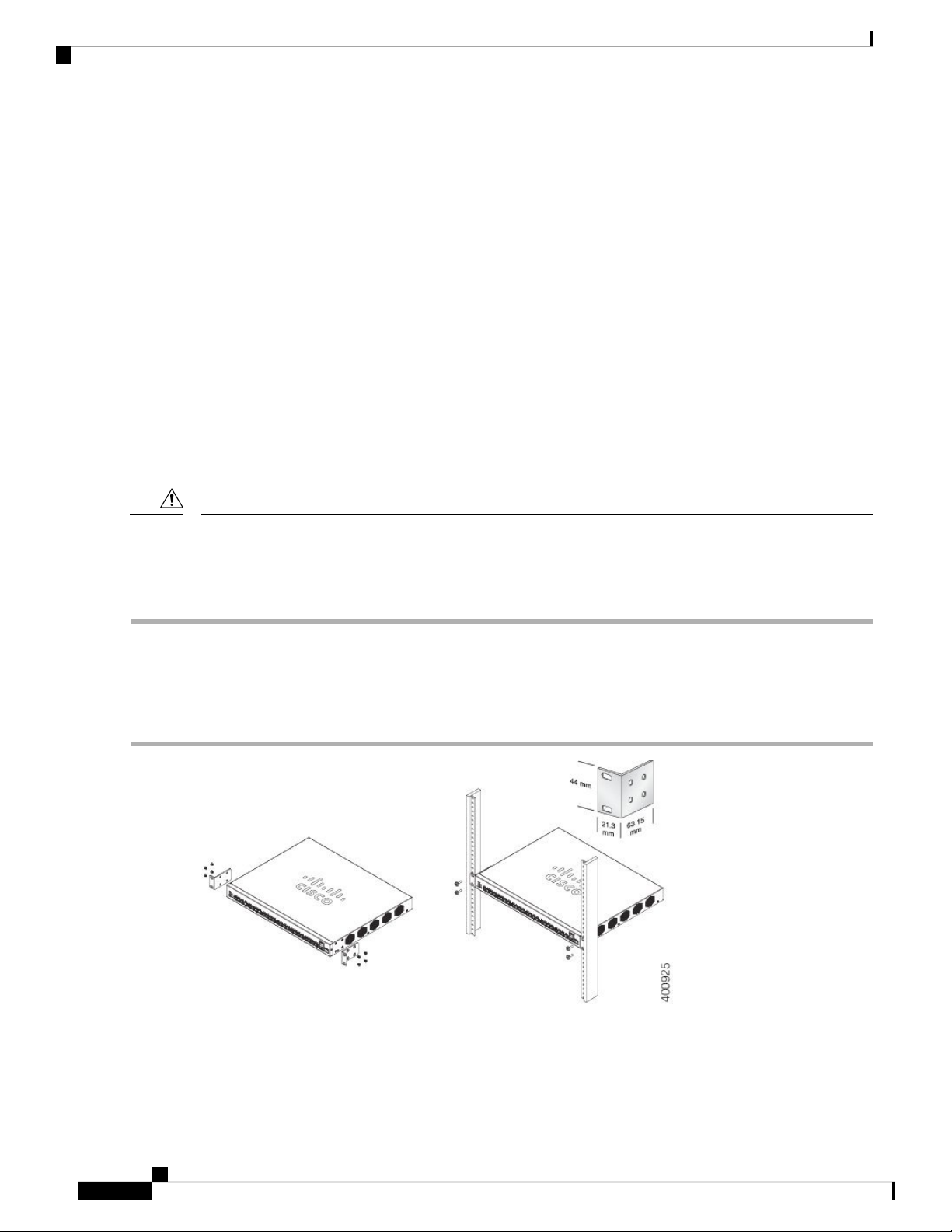
Rack Mounting Switch
You can mount the switches on any standard size, 19-inch (about 48 cm) wide rack. The switch requires 1
rack unit (RU) of space, which is 1.75 inches (44.45 mm) high.
Get To Know Your Switch
Caution
Step 1 Place one of the supplied brackets on the side of the switch so that the four holes of the brackets align to the screw holes,
and then use the four supplied screws to secure it.
Step 2 Repeat the previous step to attach the other bracket to the opposite side of the switch.
Step 3 After the brackets are securely attached, the switch is now ready to be installed into a standard 19-inch rack.
For stability, load the rack from the bottom to the top, with the heaviest devices on the bottom. A top-heavy
rack is likely to be unstable and might tip over.
To install the switch into a 19-inch standard chassis:
Cisco Business 250 Series Switches Administration Guide
2
Get To Know Your Switch
Wall Mounting a Switch
You can mount the switches on a wall, using wall studs or to a firmly attached plywood mounting backboard.
Wall Mounting a Switch
Caution
Caution
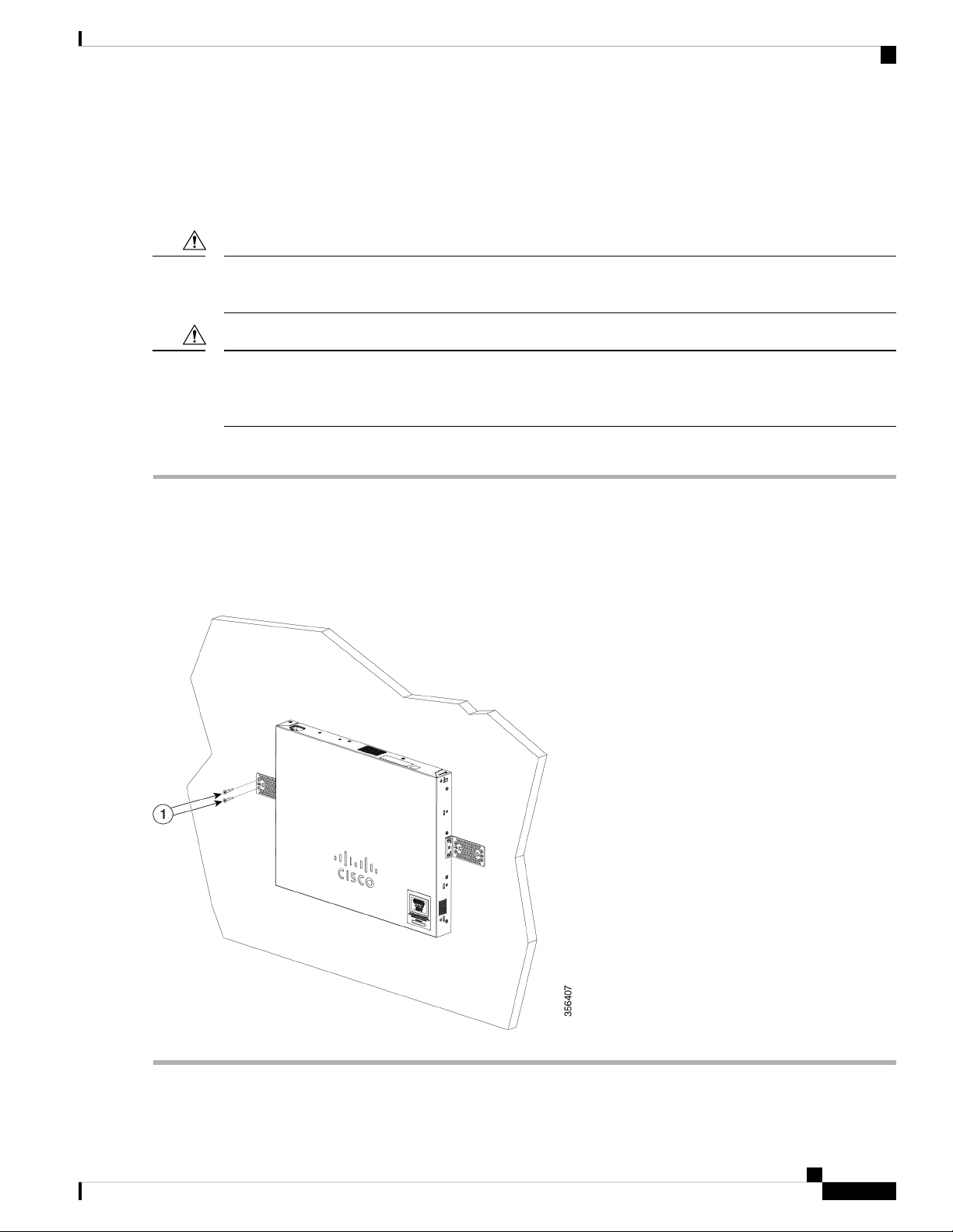
Step 1 Attach a 19-inch bracket to one side of the switch.
Step 2 Repeat the previous step to attach the other bracket to the opposite side of the switch.
Step 3 After the brackets are securely attached, mount the switch with the front panel facing down. Make sure that the switch
is attached securely to wall studs or to a firmly attached plywood-mounting backboard. Wall-mounting a 24-port switch.
Wall-mounting a 24-port
Read these instructions carefully before beginning installation. Failure to use the correct hardware or to follow
the correct procedures could result in a hazardous situation to people and damage to the system.
Do not wall-mount the switch with its front panel facing up. Following safety regulations, wallmount the
switch with its front panel facing down or to the side to prevent airflow restriction and to provide easier access
to the cables.
To wall-mount a 24-port switch using brackets:
Cisco Business 250 Series Switches Administration Guide
3
Get To Know Your Switch
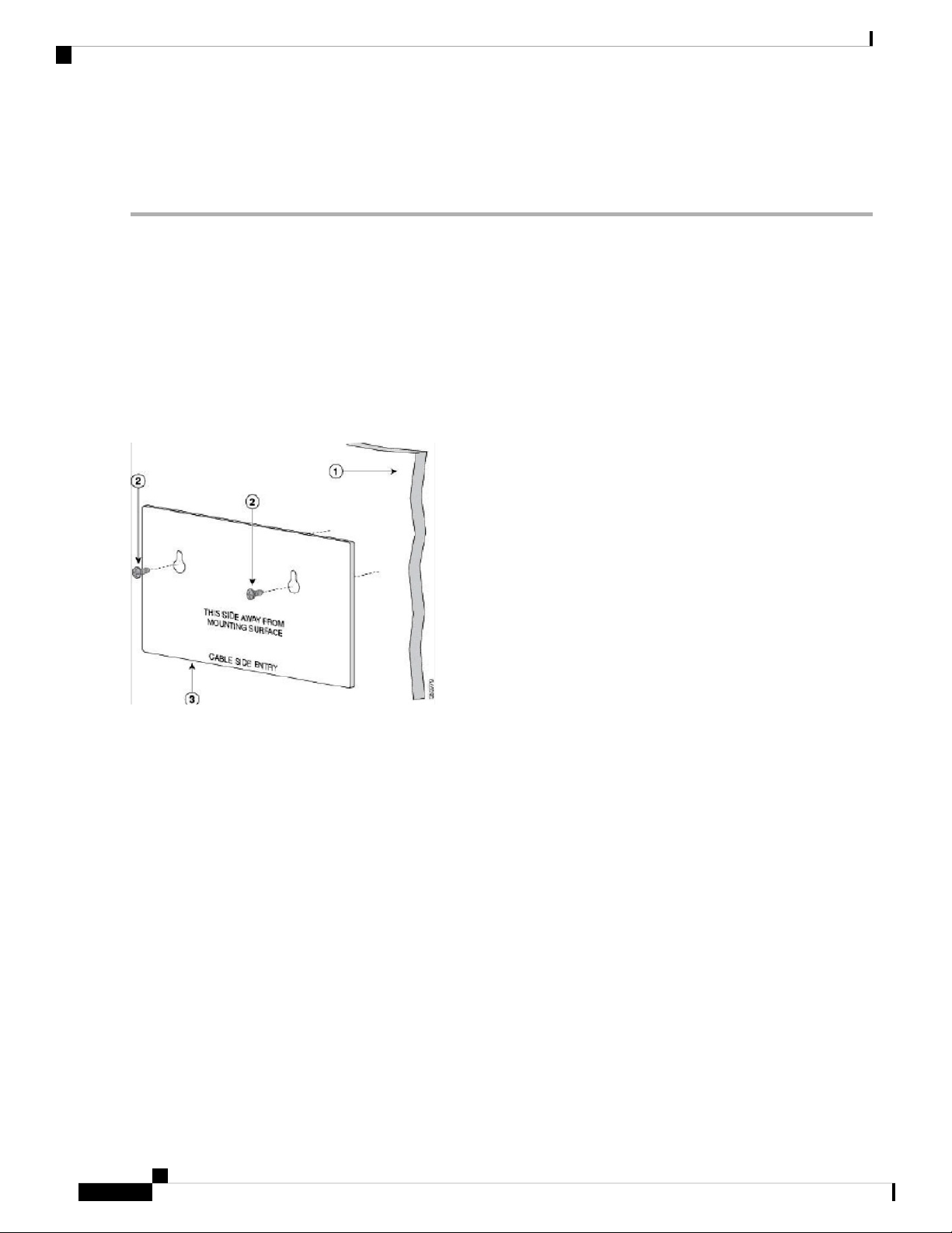
Wall Mount an 8 Port Switch
Wall Mount an 8 Port Switch
To wall-mount a 8-port switch using mounting screws, follow these steps:
Step 1 Locate the screw template. The template is used to align the mounting screw holes.
Step 2 Position the screw template so that the edge that is marked as CABLE SIDE ENTRY faces toward the floor. Make sure
that the switch is attached securely to wall studs or to a firmly attached plywoodmounting backboard.
Step 3 Peel the adhesive strip off the bottom of the screw template.
Step 4 Attach the screw template to the wall.
Step 5 Use a 0.144-inch (3.7 mm) or a #27 drill bit to drill a 1/2-inch (12.7 mm) hole in the two screw template slots.
Step 6 Insert two screws in the slots on the screw template, and tighten them until they touch the top of the screw template.
Installing the mounting screws on the wall
Figure 3 Installing the mounting screws on the wall
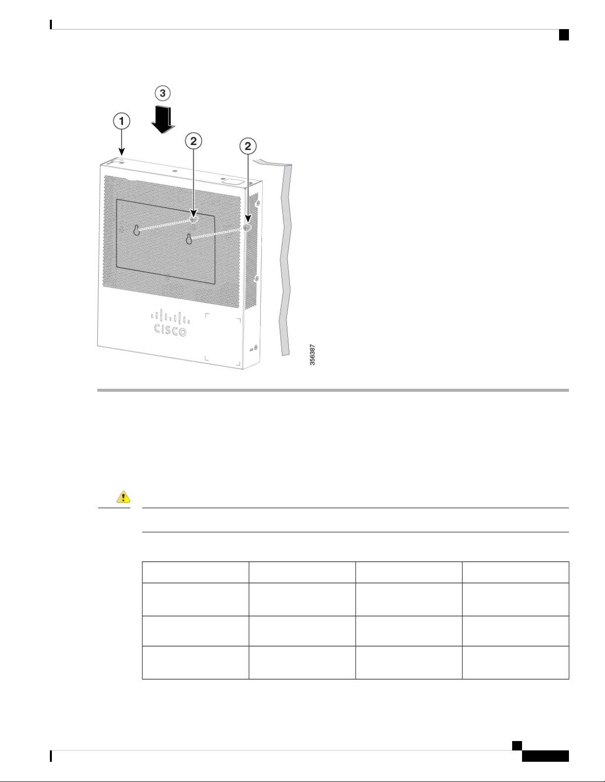
Step 7 Remove the screw template from the wall.
Step 8 Place the switch onto the mounting screws, and slide it down until it locks in place.Wall-mounting an 8-port switch
Figure 4 Wall-mounting an 8-port switch
Cisco Business 250 Series Switches Administration Guide
4
Get To Know Your Switch
Power over Ethernet Considerations
Power over Ethernet Considerations
Some switches support PoE while others do not. The switch models that support PoE have a P in their model
number, such as: CBSxxx-xxP-xx. If your switch is one of the Power over Ethernet (PoE) models, consider
the following power requirement.
Danger
The switch is to be connected only to PoE networks without routing to the outside plant.
Table 1: Switches with Power Over Ethernet
CBS250-8PP-D
Switch
CBS250-8PP-E-2G
Switch
CBS250-8P-E-2G
Switch
PoE PSE SupportPoE PD Chipset TypeDescriptionSKU Name
AF/AT1*69208M8-Port Gigabit PoE Smart
AF/ATTPS23888-Port Gigabit PoE Smart
AF/ATTPS23888-Port Gigabit PoE Smart
Cisco Business 250 Series Switches Administration Guide
5

Power over Ethernet Considerations
Get To Know Your Switch
PoE PSE SupportPoE PD Chipset TypeDescriptionSKU Name
CBS250-8FP-E-2G
CBS250-16P-2G
CBS250-24PP-4G
CBS250-24P-4G
CBS250-24FP-4G
CBS250-48PP-4G
CBS250-48P-4G
CBS250-24P-4X
CBS250-24FP-4X
AF/ATTPS23888-Port Gigabit PoE Smart
Switch
AF/AT2*TPS238816-Port Gigabit PoE
Smart Switch
AF/AT3*TPS238824-Port Gigabit PoE
Smart Switch
AF/AT3*TPS238824-Port Gigabit PoE
Smart Switch
AF/AT3*TPS238824-Port Gigabit PoE
Smart Switch
AF/AT6*TPS238848-Port Gigabit PoE
Smart Switch
AF/AT6*TPS238848-Port Gigabit PoE
Smart Switch
AF/AT3*TPS238824-Port Gigabit PoE
Smart Switch with 10G
Uplinks
AF/AT3*TPS238824-Port Gigabit PoE
Smart Switch with 10G
Uplinks
Caution
CBS250-48P-4X
AF/AT6*TPS238848-Port Gigabit PoE
Smart Switch with 10G
Uplinks
Consider the following when connecting a PoE switch. The PoE switches are PSE (Power Sourcing Equipment)
that are capable of supplying DC power to attaching powered devices (PD). These devices include VoIP
phones, IP cameras, and wireless access points. The PoE switches can detect and supply power to pre-standard
legacy PoE PD. Due to the PoE legacy support, it is possible that a PoE switch acting as a PSE may mistakenly
detect and supply power to an attaching PSE, including other PoE switches, as a legacy PD. Even though PoE
switches are PSE, and as such should be powered by AC, they could be powered up as a legacy PD by another
PSE due to false detection. When this happens, the PoE switch may not operate properly and may not be able
to properly supply power to its attaching PDs.
To prevent false detection, you should disable PoE on the ports on the PoE switches that are used to connect
to PSEs. You should also first power up a PSE device before connecting it to a PoE switch. When a device
is being falsely detected as a PD, you should disconnect the device from the PoE port and power recycle the
device with AC power before reconnecting its PoE ports.
Cisco Business 250 Series Switches Administration Guide
6
Get To Know Your Switch
Front Panel
Note
Front Panel
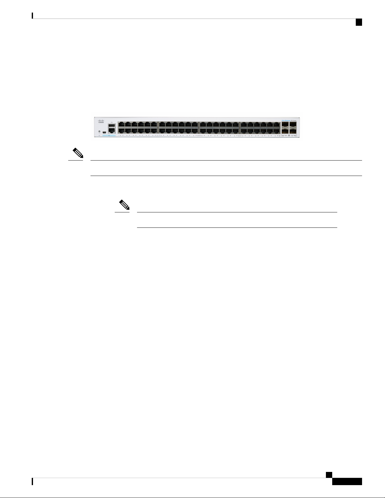
The ports, LEDs, and Reset button are located on the front panel of the switch, as well as the following
components:
Cisco Business 250 Series Model
Models may differ within the CBS 250 series and this is just a representation of a model within the series.
• Console port with RJ-45 and mini-USB connectors. The console connects a serial cable to a computer
serial port so that it can be configured using a terminal emulation program.
Note
Only certain models support this featue.
• USB Port—The USB port connects the switch to a USB device so that you can save and restore the
configuration files, firmware images, and SYSLOG files through the connected USB device.
• RJ-45 Ethernet Ports—The RJ-45 Ethernet ports connect network devices, such as computers, printers,
and access points, to the switch.
• SFP+ Port (if present)—The small form-factor pluggable plus (SFP+) are connection points for modules
so that the switch can link to other switches. These ports are also commonly referred to as mini 10GigaBit
Interface Converter ports. The term SFP+ is used in this guide.
• The SFP+ ports are compatible with the following Cisco SFP 1G optical modules MGBSX1,
MGBLX1, MGBLH1, MGBT1, as well as other brands.
• The SFP+ ports are compatible with the following Cisco SFP 1G optical modules MGBSX1,
MGBLX1, MGBLH1, MGBT1, as well as other brands.
• The Cisco SFP+ Copper Cable modules that are supported in the Cisco switches are:
SFP-H10GB-CU1M, SFP-H10GB-CU3M, and SFP-H10GB-CU5M.
• Small form-factor pluggable (SFP) ports are connection points for modules, so the switch can link
to other switches.
• The LEDs of the corresponding RJ-45 port flash green to respond to the SFP interface traffic.
• Some SFP interfaces are shared with one other RJ-45 and SFP+ port, called a combo port. When the SFP
is active, the adjacent RJ-45 port is disabled.
• Reset button is used to reset or reboot the switch. To reboot the switch, press the Reset button for less
than 10 seconds.
Cisco Business 250 Series Switches Administration Guide
7

Front Panel LEDs
Front Panel LEDs
The following are the global LEDs found on the devices:
• System—(Green) The LED lights steady when the switch is powered on, and flashes when booting,
The following LEDs describe the stacking behavior of the switch.
• Stack ID LED (Green) - The LED lights steady when the switch is stacked and the corresponding number
• Active Unit ID LED - indicating this is the stack active unit.
• System LED - Every 20 seconds, the System LED will flash according to unit ID of the member unit.
Get To Know Your Switch
performing self-tests, or acquiring an IP address. If the LED flashes Amber, the switch has detected a
hardware or firmware failure, and/or a configuration file error.
indicates its Stack ID.
• Flash = LED going off and then on again.
• According to unit ID of the unit. This means
• Unit 1 (if not active unit) - system LED will flash 1 time
• Unit 2 (if not active unit) - system LED will flash 2 times
• Unit 3 - system LED will flash 3 times
• Unit 4 -system LED will flash 4 times;
• The duration of each flash (LED off time) will be as follows:
• LED off time (in each flash) ~ 0.5 seconds.
• “Interim” LED on (between 2 LED offs) ~ 0.5 seconds
• If a member unit is removed from the stack, its system LED will continue to flash according to
above definition.
The following are per port LEDs:
• LINK/ACT—(Green) Located on the left of each port. The LED lights steady when a link between the
corresponding port and another device is detected, and flashes when the port is passing traffic.
• SFP+ (if present)—(Green) Located on the right of a 10G port. The LED lights steady when a connection
is made through the shared port, and flashes when the port is passing traffic.
• XG—(Green) Located on the right of a 10G port. The LED lights steady when another device is connected
to the port, is powered on, and a 10 Gbps link is established between the devices. When the LED is off,
the connection speed is under 10 Gbps or nothing is cabled to the port.
• Gigabit—(Green) Located on the right of the OOB and 1G port. The LED lights steady when another
device is connected to the port, is powered on, and a 1000 Mbps link is established between the devices.
When the LED is off, the connection speed is under 1000 Mbps or nothing is cabled to the port.
• PoE (if present)—(Amber) Located on the right of the port. The LED lights steady when power is being
supplied to a device attached to the corresponding port.
Cisco Business 250 Series Switches Administration Guide
8

Get To Know Your Switch
Configuring Switches
The switch can be accessed and managed by two different methods; over your IP network using the web-based
interface, or by using the switch’s command-line interface through the console port. Using the console port
requires advanced user skills.
The following table shows the default settings used when configuring your switch for the first time.
Default ValueParameter
ciscoUsername
ciscoPassword
192.168.1.254LAN IP
Configuring Your Switch Using the Web-based Interface
Configuring Switches
To access the switch with a web-based interface, you must know the IP address that the switch is using. The
switch uses the factory default IP address of 192.168.1.254, with a subnet of /24. When the switch is using
the factory default IP address, the System LED flashes continuously. When the switch is using a DHCP
server-assigned IP address or an administrator has configured a static IP address, the System LED is a steady
green (DHCP is enabled by default).
If you are managing the switch through a network connection and the switch IP address is changed, either by
a DHCP server or manually, your access to the switch will be lost. You must enter the new IP address that
the switch is using into your browser to use the web-based interface. If you are managing the switch through
a console port connection, the link is retained.
To configure the switch using the web-based interface:
Step 1 Power on the computer and your switch.
Step 2 Connect the computer to any network port.
Step 3 Set up the IP configuration on your computer.
a) If the switch is using the default static IP address of 192.168.1.254/24, you must choose an IP address for the computer
in the range of 192.168.1.2 to 192.168.1.253 that is not already in use.
b) If the IP addresses will be assigned by DHCP, make sure that your DHCP server is running and can be reached from
the switch and the computer. You may need to disconnect and reconnect the devices for them to discover their new
IP addresses from the DHCP server.
Note
Details on how to change the IP address on your computer depend upon the type of architecture and operating
system that you are using. Use your computers local Help and Support functionality and search for “IP
Addressing.”
Step 4 Open a web browser window.
Step 5 Enter the switch IP address in the address bar and press Enter. For example, http://192.168.1.254.
Step 6 When the login page appears, choose the language that you prefer to use in the web-based interface and enter the username
and password.
Cisco Business 250 Series Switches Administration Guide
9

Configuring Your Switch Using the Console Port
The default username is cisco. The default password is cisco. Usernames and passwords are both case sensitive.
Step 7 Click Log In.
If this is the first time that you have logged on with the default username and password, the Change username and Password
page opens. The rules for constructing a new password are displayed on the page.
Step 8 Enter a new username and password and confirm.
Get To Know Your Switch
Note
Password complexity is enabled by default. The password must comply with the default complexity rules.
Step 9 Click Apply.
Caution
Make sure that any configuration changes made are saved before exiting from the web-based interface by
clicking on the Save icon. Exiting before you save your configuration results in all changes being lost.
The Getting Started page opens. You are now ready to configure the switch. Refer to the Administration Guide or see
the help pages for further information.
Configuring Your Switch Using the Console Port
To configure the switch using the console port, proceed with the following steps:
Step 1 Connect a computer to the switch console port using a Cisco console cable (purchased separately) or a cable with mini
USB connector.
Step 2 Start a console port utility such as HyperTerminal on the computer.
Step 3 Configure the utility with the following parameters:
• 115200 bits per second
• 8 data bits
• no parity
• 1 stop bit
• no flow control
Step 4 Enter a username and password. The default username is cisco, and the default password is cisco. Usernames and passwords
are both case sensitive.
If this is the first time that you have logged on with the default username and password, the following message appears:
Please change your username AND password from the default settings. Change of credentials
is required for better protection of your network.
Please note that new password must follow password complexity rules
Step 5 Set a new administrator username and password.
Caution
Make sure that any configuration changes made are saved before exiting.
You are now ready to configure the switch. See the CLI Guide for your switch.
Cisco Business 250 Series Switches Administration Guide
10

Get To Know Your Switch
Navigation
Note
Console access also provides additional interfaces for debug access which are not available via the web interface. These
debug access interfaces are intended to be used by a Cisco Support Team personnel, in cases where it is required to debug
device’s behavior. These interfaces are password protected. The passwords are held by the Cisco support team. The device
supports the following debug access interfaces:
• U-BOOT access during boot sequence
• Linux Kernel access during boot sequence
• Run time debug modes - allows Cisco support team to view device settings and apply protocol and layer 1 debug
commands and settings. The run time debug mode is accessible over telnet and SSH terminals in addition to console.
Navigation
If you are not using DHCP on your network, set the IP address type on the switch to Static and change the static
IP address and subnet mask to match your network topology. Failure to do so may result in multiple switches
using the same factory default IP address of 192.168.1.254.
The navigation menu, located at the top right of each UI page, lists the device’s main features.You can access
each feature’s UI pages using a series of cascading menus. To access an individual UI page, click the
corresponding feature tab in the navigation menu to display a menu of subcategories. Select a subcategory
and repeat this process until you see the desired page, and then select the page to display it in the main window.
Basic or Advanced Display Mode
The product supports many features, and therefore the WEB GUI includes hundreds of configuration and
display pages. These pages are divided into the following display modes:
• Basic—Basic subset of configuration options are available. If you are missing some configuration option,
select the Advanced mode in the device header.
• Advanced—Full set of configuration options are available.
When the user switches from basic to advanced, the browser reloads the page. However, after reload, the user
stays on the same page. When the user switches from advanced to basic, the browser reloads the page. If the
page exists also on the basic mode, the user stays on the same page. If the page does not exist in the basic
mode, the browser will load the first page of the folder which was used by the user. If the folder does not
exist, the Getting Started page will be displayed.
If there is advanced configuration, and the page is loaded in basic mode, a page-level message will be displayed
to the user (e.g. there are 2 radius server configured but in basic mode only a single server can be displayed,
or there is 802.1X port authentication with time range configured but time range is not visible in basic mode).
When switching from one mode to another, any configuration which was made on the page (without Apply)
is deleted.
Management Buttons
The following table describes the commonly-used buttons that appear on various pages in the system.
Cisco Business 250 Series Switches Administration Guide
11
Management Buttons
Get To Know Your Switch
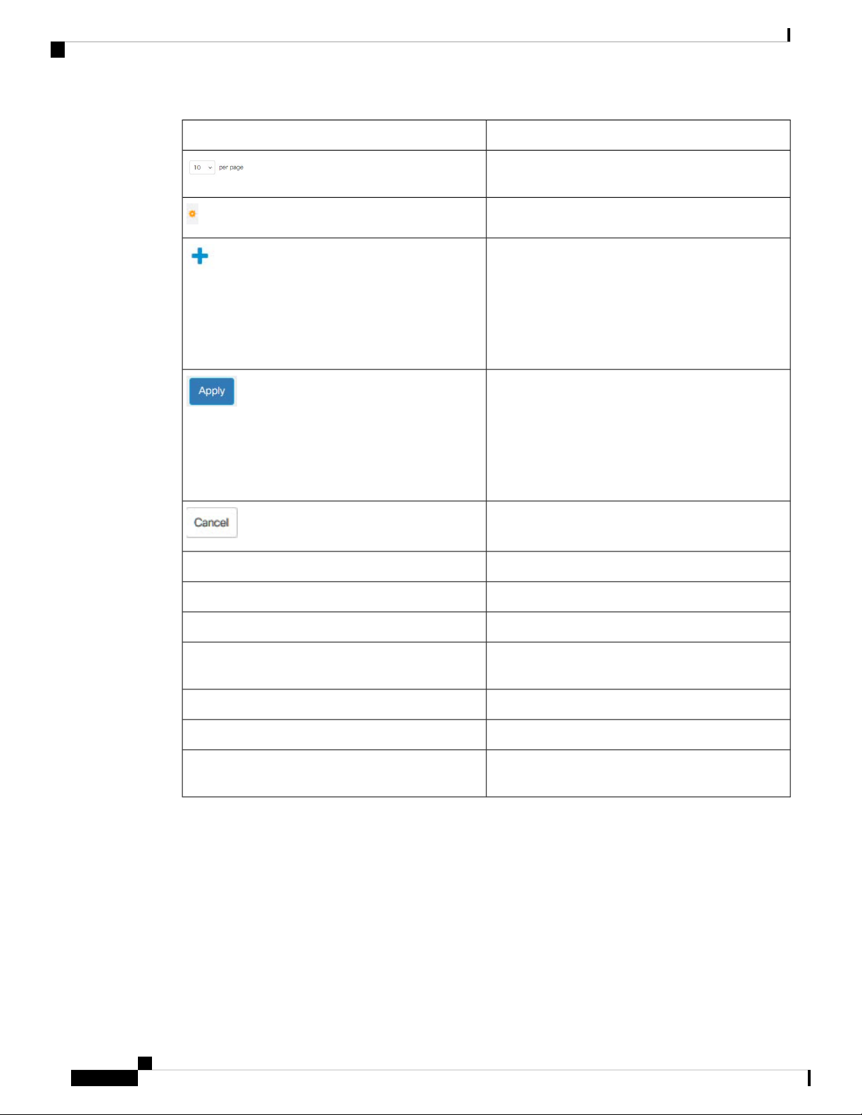
DescriptionButton Name
Use the pull-down menu to configure the number of
entries per page.
Indicates a mandatory field.
Click to display the related Add page and add an entry
to a table. Enter the information and click Apply to
save it to the Running Configuration. Click Close to
return to the main page. Click Save to display the
Copy/Save Configuration page and save the Running
Configuration to the Startup Configuration file type
on the device.
Click to apply changes to the Running Configuration
on the device. If the device is rebooted, the Running
Configuration is lost, unless it is saved to the Startup
Configuration file type or another file type. Click Save
to display the Copy/Save Configuration page and save
the Running Configuration to the Startup
Configuration file type on the device.
Clear Interface Counters
Close
Click to reset changes made on the page.
Clear information on page.Clear
Click to clear filter to select information displayed.Clear Filter
Click to clear the statistic counters for all interfaces.Clear All Interface Counters
Click to clear the statistic counters for the selected
interface.
Clears log files.Clear Log
Clears table entries.Clear Table
Returns to main page. If any changes were not applied
to the Running Configuration, a message appears.
Cisco Business 250 Series Switches Administration Guide
12
Get To Know Your Switch
Application Header
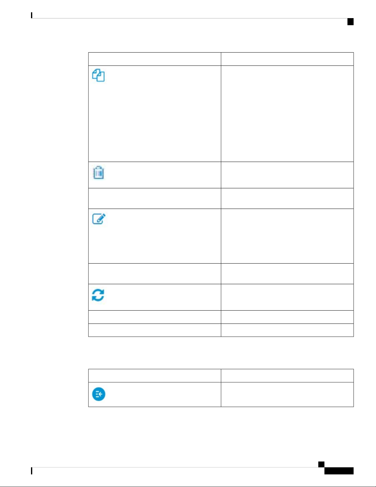
DescriptionButton Name
A table typically contains one or more entries
containing configuration settings. Instead of modifying
each entry individually, it is possible to modify one
entry and then copy the selected entry to multiple
entries, as described below:
1. Select the entry to be copied. Click Copy Settings
to display.
2. Enter the destination entry numbers in the to field.
3. Click Apply to save the changes and click Close
to return to the main page.
After selecting an entry in the table, click Delete to
remove.
Details
Go
Application Header
The Application Header appears on every page. It provides the following application links:
Click to display the details associated with the entry
selected.
Select the entry and click Edit. The Edit page appears,
and the entry can be modified.
1. Click Apply to save the changes to the Running
Configuration.
2. Click Close to return to the main page.
Enter the query filtering criteria and click Go. The
results are displayed on the page.
Click Refresh to refresh the counter values.
Click Test to perform the related tests.Test
Click Restore Defaults to restore factory defaults.Restore Defaults
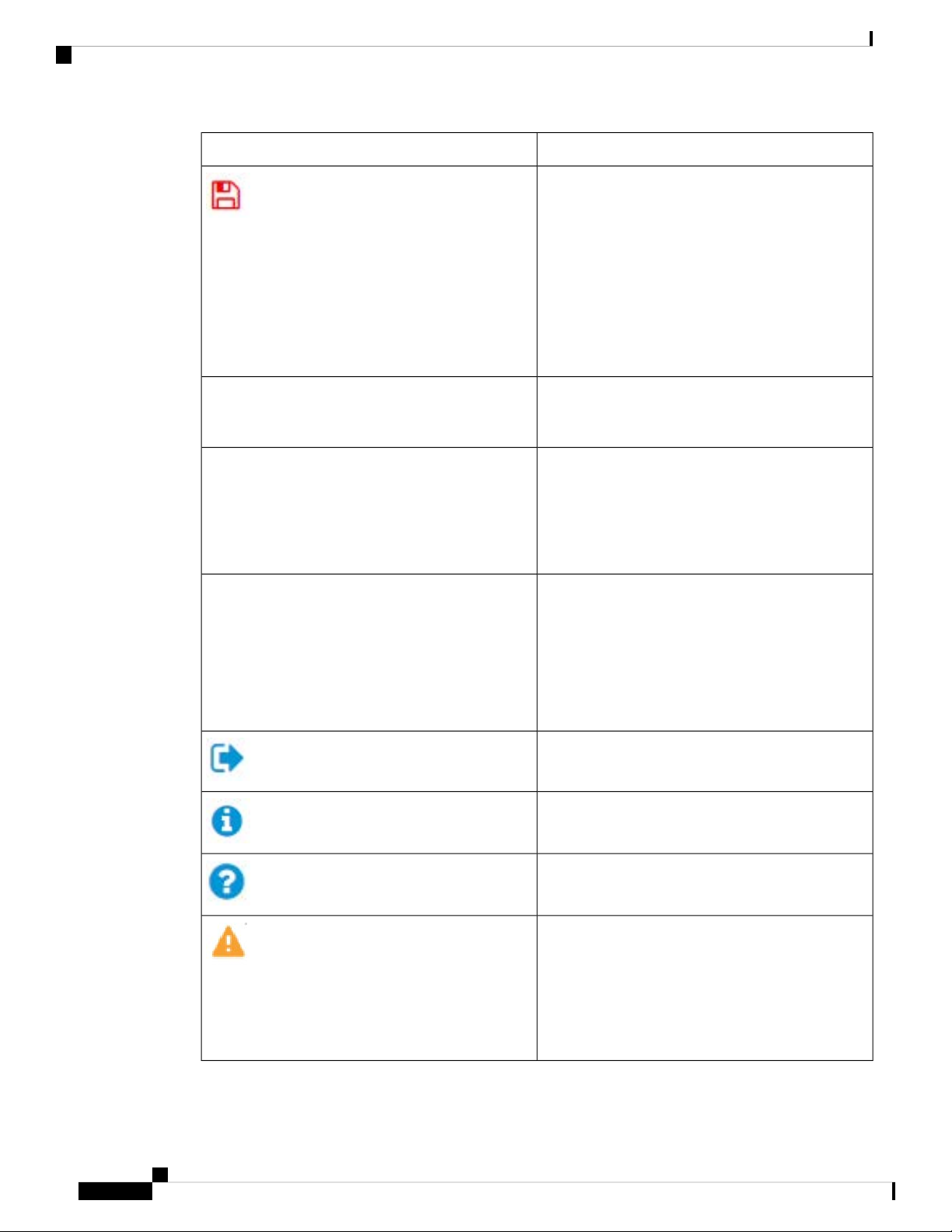
DescriptionApplication Link Name
Show/hide the navigation pane.
Cisco Business 250 Series Switches Administration Guide
13
Application Header
Get To Know Your Switch
DescriptionApplication Link Name
A flashing red icon displayed to the right of the Search
option indicates that Running Configuration changes
have been made that have not yet been saved to the
Startup Configuration file.
Click the icon to save the configuration. After this
save, the red icon does not appear on the header. When
the device is rebooted, it copies the Startup
Configuration file type to the Running Configuration
and sets the device parameters according to the data
in the Running Configuration.
Username
Host Name
Language Menu
Displays the name of the user logged on to the device.
The default username is cisco. (The default password
is cisco ).
Displays the host name assigned in the System
Settings page. If the host name is longer than 20
character, only the first 20 characters will be displayed
with an ellipsis (...) appended. Hovering over the
truncated hostname displays a tooltip showing the full
host name.
This menu provides the following options:
• Select a language: Select one of the languages
that appear in the menu. This language will be
the web-based configuration utility language.
• Download Language: Add a new language to the
device.
Click to log out.
Click to display the device name and device version
number.
Click to display the online help.
The SYSLOG Alert Status icon appears when a
SYSLOG message, above the critical severity level,
is logged. Click the icon to open the RAM Memory
page. After you access this page, the SYSLOG Alert
Status icon is no longer displayed. To display the page
when there is not an active SYSLOG message, Click
Status and Statistics> View Log > RAM Memory.
Cisco Business 250 Series Switches Administration Guide
14

Getting Started
This chapter contains the following section:
• Getting Started, on page 15
Getting Started
This section will guide you on how to install and manage your device.
Click on Getting Started to access the page where you can use the various links and follow the on-screen
instructions to quickly configure your switch.
Basic or Advanced Display Mode
The switch's WEB GUI includes hundreds of configuration and display pages. These pages are divided into
the following display modes:
• Basic—Basic subset of configuration options.
• Advanced—Full set of configuration options are available
CHAPTER 2
When switching from one mode to another, any configuration which was made on the page (without Apply)
is deleted.
Initial Setup
TCP/UDP Services, on page 205Change Management Applications
and Services
IPv4 Interface, on page 161Change Device IP Address
VLAN Settings, on page 123Create VLAN
Port Settings, on page 103Configure Port Settings
Device Status
System Summary, on page 31System Summary
Interface, on page 34Port Statistics
Cisco Business 250 Series Switches Administration Guide
15
Getting Started
Getting Started
Statistics, on page 44RMON Statistics
RAM Memory, on page 49View Log
Quick Access
User Accounts, on page 52Change Device Password
Firmware Operations, on page 63Upgrade Device Software
File Operations, on page 65Backup Device Configuration
MAC-Based ACL, on page 223Create MAC-Based ACL
IPv4-based ACL, on page 225Create IP-Based ACL
QoS Properties, on page 235Configure QoS
SPAN , on page 40Configure SPAN
There are two hot links on the Getting Started page that take you to Cisco web pages for more information.
Clicking on the Support link takes you to the device product support page, and clicking on the Forums link
takes you to the Support Community page.
Cisco Business 250 Series Switches Administration Guide
16

Dashboard
CHAPTER 3
Dashboard
This chapter contains the following section:
• Dashboard, on page 17
The dashboard is a collection of 8 squares, initially empty, that can be populated by various types of information.
You can select a number of modules from the available modules and place them in this grid. You can also
customize settings of the currently-displayed modules.When the dashboard loads, the modules you selected
for the dashboard are loaded in their locations in the grid. The data in the modules is updated, in intervals
depending on the module type.
When you open the dashboard, a wire frame view of the grid is displayed. To display modules that aren’t
currently being displayed, click Customize. Add modules by selecting a module from the list of modules on
the right and dragging and dropping it to any space in the grid.
The modules are divided into the following groups:
• Small Modules are modules that take up a single square.
• Large Modules take up two squares.
If you drag a module into a space currently occupied, the new module replaces the previous one. You can
rearrange the placement of the modules in the grid by dragging a module from one occupied grid position to
another position. Only when you click Done are the modules populated by the relevant information. The title
bar of each module in the dashboard displays the title of the module and three buttons.
• Pencil — Opens configuration options (depending on the module).
• Refresh — Refreshes the information.
• X — Removes the module from the dashboard.
Cisco Business 250 Series Switches Administration Guide
17

Dashboard
Dashboard
Table 2: Small Modules
System Health
Resource Utilization
The System Health displays information about device health.
• Fan Status
• Yellow— A fan has failed and is backed up by a redundant
fan.
• Green—Fan is operational.
• Red—Fan is faulty.
• Thermometer Status
• Green —Temperature is OK.
• Yellow—Temperature generates a warning.
• Red—Temperature is critical.
This module displays the utilization status in terms of a percentage of
the various system resources as a bar chart
The resources monitored are:
• Multicast Groups—Percentage of Multicast groups that exist out
of the maximum possible number that are permitted to be defined.
• MAC Address Table—Percentage of MAC Address table in use.
Identification
• TCAM—Percentage of TCAM used by QoS and ACL entries.
• CPU—Percentage of CPU being used.
This module displays basic information regarding the device. It displays
the following fields:
• System Description—Displays description of the device.
• Host Name—Entered in the System Settings, on page 51 or default
is used.
• Firmware Version—Current firmware version running on device.
• MAC Address—MAC address of the device.
• Serial Number—Serial number of the device.
• System Location (if configured)—Enter the physical location of
the device.
• System Contact (if configured)—Enter the name of a contact person.
• Total Available Power (for PoE devices only)—Amount of power
available to the device.
• Current Power Consumption (for PoE devices only)—Amount of
power consumed by the device.
Cisco Business 250 Series Switches Administration Guide
18

Dashboard
Dashboard
PoE Utilization
Table 3: Large Modules
Latest Logs
This module displays a graphic representation of the PoE utilization
status. For a standalone unit, this module displays a gauge with a dial
of values from 0-100. The section of the dial from the traps threshold
to 100 is red. In the middle of the gauge, the actual PoE utilization value
is shown in watts.
Each bar represents the PoE utilization percentage value of the device
on a scale of 0 to 100. If the PoE utilization is higher than the traps
threshold, the bar is red. Otherwise the bar is green. When hovering on
a bar, a tooltip appears showing the actual PoE utilization of the device
in watts. Additional views can be selected in the configuration options
(pencil icon in upper-right corner).
• Refresh Time—Select one of the displayed options.
• PoE Global Properties—Link to the Port Management > PoE >
Properties page.
• PoE Port Settings—Link to the Port Management > PoE >
Settings page.
This module contains information about the five latest events logged by
the system as SYSLOGs. The following configuration options
(right-hand corner) are available:
• Severity Threshold—Described in Log Settings, on page 60.
• Refresh Time—Select one of the options displayed.
• View logs—Click to open RAM Memory, on page 49 .
Cisco Business 250 Series Switches Administration Guide
19

Dashboard
Dashboard
Suspended Interfaces
Port Utilization
This module displays interfaces that have been suspended in either
device or table view. The view is selected in the configuration options
- Display Option (pencil icon in upper-right corner).
• Device View—In this view, the device is displayed. When units
are connected in a stack, a drop-down selector enables the user to
select the device to be viewed. All suspended ports in the device
are shown as red.
• Table View—In this view, there is no need to select a specific stack
unit. Information is displayed in table form as follows:
• Interface—Port or LAG that was suspended
• Suspension Reason—Reason interface was suspended
• Auto-recovery current status—Has auto recovery been enable
for the feature that caused the suspension.
The following configuration options (right-hand corner) are available:
• Refresh Time—Select one of the options displayed
• Error Recovery Settings—Click to open Error Recovery Settings,
on page 106.
This section displays the port utilization on the device. The view is
selected in the configuration options (pencil icon in upper-right corner).
• Display Mode—Device View - Displays the device Hovering over
a port displays information about it.
• Display Mode—Chart View - A list of ports and how they are being
used is displayed. For each port, the following port utilization
information can be viewed.
• Tx—% (red)
• Rx—% (blue)
• Refresh Time—Select one of the displayed options.
• Interface Statistics—Link to the Status and Statistics> Interface.
Cisco Business 250 Series Switches Administration Guide
20

Dashboard
Dashboard
Traffic Errors
This modules displays the number of error packets of various types that
are counted on the RMON statistics. The view is selected in the
configuration options (pencil icon in upper-right corner).
• Display Mode - Device View
The device module mode displays a diagram of the device. All
suspended ports in the device are shown as red.
Hovering over a suspended port displays a tooltip with the following
information:
• Port name.
• If the port is a member of a LAG, the LAG identity of the
port.
• Details of the last error logged on the port.
• Display Mode - Table View
• Interface—Name of port
• Last Traffic Error—Traffic error that occurred on a port and
the last time the error occurred.
• Refresh Time—Select one of the refresh rates.
• Traffic Error Information—Click to link to the Statistics, on page
44.
Cisco Business 250 Series Switches Administration Guide
21

Dashboard
Dashboard
Cisco Business 250 Series Switches Administration Guide
22

CHAPTER 4
Configuration Wizards
This chapter contains the following sections:
• Getting Started Wizard, on page 23
• VLAN Configuration Wizard, on page 24
• ACL Configuration Wizard, on page 25
Getting Started Wizard
The Getting Started Wizard will assist you in the initial configuration of the device.
Step 1 In Configuration Wizards > GettingStarted Wizard, click Launch Wizard.
Step 2 Click Launch Wizard and Next.
Step 3 Enter the fields in the General Information tab:
• System Location—Enter the physical location of the device.
• System Contact—Enter the name of a contact person.
• Host Name—Select the host name of this device. This is used in the prompt of CLI commands:
• Use Default—The default hostname (System Name) of these switches is: switch 123456, where 123456
represents the last three bytes of the device MAC address in hex format.
• User Defined—Enter the hostname. Use only letters, digits, and hyphens. Host names cannot begin or end
with a hyphen. No other symbols, punctuation characters, or blank spaces are permitted (as specified in
RFC1033, 1034, 1035).
Step 4 Click Next.
Step 5 Enter the fields in the IP Settings tab:
• Interface—Select the IP interface for the system.
• IP Interface Source—Select one of the following options:
• DHCP—Select for the device to receive its IP address from a DHCP server.
• Static—Select to enter the IP address of the device manually.
Cisco Business 250 Series Switches Administration Guide
23

VLAN Configuration Wizard
• If you selected Static as the IP interface source, enter the following fields:
• IP Address—IP address of the interface.
• Network Mask—IP mask for this address.
• Administrative Default Gateway—Enter the default gateway IP address.
• DNS Server—Enter the IP address of the DNS server.
Step 6 Click Next
Step 7 Enter the fields in the User Account tab:
• Username—Enter a new user name between 0 and 20 characters. UTF-8 characters are not permitted.
• Password—Enter a password (UTF-8 characters are not permitted). If the password strength and complexity is
defined, the user password must comply with the policy configured in Password Strength, on page 189.
• Confirm Password—Enter the password again.
• Password Strength —Displays the strength of password. The policy for password strength and complexity are
configured in the Password Strength, on page 189.
Configuration Wizards
• Keep current username and password—Select to keep current username and password.
Step 8 Click Next
Step 9 Enter the fields in the Time Settings tab:
• Clock Source—Select one of the following:
• Manual Settings—Select to enter the device system time. If this is selected, enter the Date and Time.
• Default SNTP Servers—Select to use the default SNTP servers.
Note
• Manual SNTP Server—Select and enter the IP address of an SNTP server.
Step 10 Click Next to view a summary of configuration that you entered.
Step 11 Click Apply to save the configuration data.
The default SNTP servers are defined by name, thus DNS must be configured and operational.
VLAN Configuration Wizard
The VLAN Configuration Wizard will assist you in configuring the VLANs. Each time you run this wizard,
you can configure the port memberships in a single VLAN. To use the VLAN Configuration Wizard to
configure your VLANs follow these steps:
Step 1 In Configuration Wizards > VLANConfiguration Wizard, click Launch Wizard.
Step 2 Click Launch Wizard and Next.
Cisco Business 250 Series Switches Administration Guide
24

Configuration Wizards
ACL Configuration Wizard
Step 3 Select the ports that are to be configured as trunk port (by clicking with mouse on the required ports in the graphical
display). Ports that are already configured as Trunk ports are pre-selected.
Step 4 Click Next.
Step 5 Enter the fields:
• VLAN ID—Select the VLAN you want to configure. You can select either an existing VLAN or New VLAN.
• New VLAN ID—Enter the VLAN ID of a new VLAN.
• VLAN Name—Optionally, enter VLAN name.
Step 6 Select the trunk ports that are to be configured as untagged members of the VLAN (by clicking with mouse on the
required ports in the graphical display). The trunk ports that are not selected in this step becomes tagged members of
the VLAN.
Step 7 Click Next.
Step 8 Select the ports are that to be the access ports of the VLAN. Access ports of a VLAN is untagged member of the VLAN.
(by clicking with mouse on the required ports in the graphical display).
Step 9 Click Next to see the summary of the information that you entered.
Step 10 Click Apply.
ACL Configuration Wizard
The ACL Configuration Wizard will assist you when creating a new ACL, or editing an existing ACL. To
add or modify an existing ACL, complete the following steps:
Step 1 In Configuration Wizards > ACL Configuration Wizard, click Launch Wizard.
Step 2 To create a new ACL, click Next. To edit an existing ACL, choose it from the ACL drop-down list and then click Next.
Step 3 Enter the fields:
• ACL Name—Enter the name of a new ACL.
• ACL Type—Select the type of ACL: IPv4 or MAC.
Step 4 Click Next.
Step 5 Enter the fields:
• Action on match—Select one of the options:
• Permit Traffic—Forward packets that meet the ACL criteria.
• Deny Traffic—Drop packets that meet the ACL criteria.
• Shutdown Interface—Drop packets that meet the ACL criteria, and disable the port from where the packets
received.
Step 6 For a MAC-based ACL, enter the fields:
Cisco Business 250 Series Switches Administration Guide
25
ACL Configuration Wizard
Configuration Wizards
Source MAC Address
Source MAC Value
Mask
Destination MAC Address
Destination MAC Value
Destination MAC Wildcard
Mask
Time Range Name
Select Any if all source address are acceptable or User defined to enter a source address
or range of source addresses.
Enter the MAC address to which the source MAC address is to be matched and its mask
(if relevant).
Enter the mask to define a range of MAC addresses.Source MAC Wildcard
Select Any if all destination addresses are acceptable or User defined to enter a destination
address or a range of destination addresses.
Enter the MAC address to which the destination MAC address is to be matched and its
mask (if relevant).
Enter the mask to define a range of MAC addresses. Note that this mask is different than
in other uses, such as subnet mask. Here, setting a bit as 1 indicates don't care and 0
indicates to mask that value.
Note
Given a mask of 0000 0000 0000 0000 0000 0000 1111 1111 (which means
that you match on the bits where there is 0 and don't match on the bits where
there are 1's). You need to translate the 1's to a decimal integer and you write
0 for each four zeros. In this example since 1111 1111 = 255, the mask would
be written: as 0.0.0.255.
If Time Range is selected, select the time range to be used. Time ranges are defined in
Time Range, on page 59. This field is only displayed if a Time Range was previously
created.
Step 7 For a IPv4-based ACL, enter the fields:
Protocol
Select one of the following options to create an ACL based on a specific protocol:
• Any (IP)—Accept all IP protocols packets
• TCP—Accept Transmission Control Protocols packets
• UDP—Accept User Datagram Protocols packets
• ICMP—Accept ICMP Protocols packets
• IGMP—Accept IGMP Protocols packets
Select a port from the drop-down list.Source Port for TCP/UDP
Select a port from the drop-down list.Destination Port for
TCP/UDP
Source IP Address
Select Any if all source address are acceptable or User defined to enter a source address
or range of source addresses.
Enter the IP address to which the source IP address is to be matched.Source IP Value
Cisco Business 250 Series Switches Administration Guide
26
Configuration Wizards
ACL Configuration Wizard
Source IP Wildcard Mask
Enter the mask to define a range of IP addresses. Note that this mask is different than
in other uses, such as subnet mask. Here, setting a bit as 1 indicates don't care and 0
indicates to mask that value.
Enter the IP address to which the source IP address is to be matched.Destination IP Address
Destination IP Wildcard Mask
Enter the mask to define a range of IP addresses. Note that this mask is different than
in other uses, such as subnet mask. Here, setting a bit as 1 indicates don't care and 0
indicates to mask that value.
Time Range Name
If Time Range is selected, select the time range to be used. Time ranges are defined
in Time Range, on page 59. This field is only displayed if a Time Range was previously
created.
Step 8 Click Next.
Step 9 Confirm that you want the ACL and ACE to be created.
The details of the ACL rule are displayed. You can click Add another rule to this ACL to add another rule.
Step 10 Click Next and enter the ACL Binding information:
• Binding Type—Select one of the following options to bind the ACL:
• Physical interfaces only—Bind the ACL to a port. In this case, click a port or ports on which to bind the ACL.
• VLANs only—Bind the ACL to a VLAN. Enter the list of VLANs in the Enter the list of VLANs you want
to bind the ACL to field.
• No binding—Do not bind the ACL.
Click Apply.
Cisco Business 250 Series Switches Administration Guide
27

ACL Configuration Wizard
Configuration Wizards
Cisco Business 250 Series Switches Administration Guide
28
Loading...