


 Loading...
Cisco ASR 1001-X Router Hardware
Installation Guide
July 28, 2014
Cisco Systems, Inc.
www.cisco.com
Cisco has more than 200 offices worldwide. Addresses, phone numbers, and fax numbers are listed on the Cisco website at www.cisco.com/go/offices.
Text Part Number: OL-32376-03
THE SPECIFICATIONS AND INFORMATION REGARDING THE PRODUCTS IN THIS MANUAL ARE SUBJECT TO CHANGE WITHOUT NOTICE. ALL STATEMENTS, INFORMATION, AND RECOMMENDATIONS IN THIS MANUAL ARE BELIEVED TO BE ACCURATE BUT ARE PRESENTED WITHOUT WARRANTY OF ANY KIND, EXPRESS OR IMPLIED. USERS MUST TAKE FULL RESPONSIBILITY FOR THEIR APPLICATION OF ANY PRODUCTS.
THE SOFTWARE LICENSE AND LIMITED WARRANTY FOR THE ACCOMPANYING PRODUCT ARE SET FORTH IN THE INFORMATION PACKET THAT SHIPPED WITH THE PRODUCT AND ARE INCORPORATED HEREIN BY THIS REFERENCE. IF YOU ARE UNABLE TO LOCATE THE SOFTWARE LICENSE OR LIMITED WARRANTY, CONTACT YOUR CISCO REPRESENTATIVE FOR A COPY.
The following information is for FCC compliance of Class A devices: This equipment has been tested and found to comply with the limits for a Class A digital device, pursuant to part 15 of the FCC rules. These limits are designed to provide reasonable protection against harmful interference when the equipment is operated in a commercial environment. This equipment generates, uses, and can radiate radio-frequency energy and, if not installed and used in accordance with the instruction manual, may cause harmful interference to radio communications. Operation of this equipment in a residential area is likely to cause harmful interference, in which case users will be required to correct the interference at their own expense.
The following information is for FCC compliance of Class B devices: This equipment has been tested and found to comply with the limits for a Class B digital device, pursuant to part 15 of the FCC rules. These limits are designed to provide reasonable protection against harmful interference in a residential installation. This equipment generates, uses and can radiate radio frequency energy and, if not installed and used in accordance with the instructions, may cause harmful interference to radio communications.
However, there is no guarantee that interference will not occur in a particular installation. If the equipment causes interference to radio or television reception, which can be determined by turning the equipment off and on, users are encouraged to try to correct the interference by using one or more of the following measures:
•Reorient or relocate the receiving antenna.
•Increase the separation between the equipment and receiver.
•Connect the equipment into an outlet on a circuit different from that to which the receiver is connected.
•Consult the dealer or an experienced radio/TV technician for help.
Modifications to this product not authorized by Cisco could void the FCC approval and negate your authority to operate the product.
The Cisco implementation of TCP header compression is an adaptation of a program developed by the University of California, Berkeley (UCB) as part of UCB’s public domain version of the UNIX operating system. All rights reserved. Copyright © 1981, Regents of the University of California.
NOTWITHSTANDING ANY OTHER WARRANTY HEREIN, ALL DOCUMENT FILES AND SOFTWARE OF THESE SUPPLIERS ARE PROVIDED “AS IS” WITH ALL FAULTS. CISCO AND THE ABOVE-NAMED SUPPLIERS DISCLAIM ALL WARRANTIES, EXPRESSED OR IMPLIED, INCLUDING, WITHOUT LIMITATION, THOSE OF MERCHANTABILITY, FITNESS FOR A PARTICULAR PURPOSE AND NONINFRINGEMENT OR ARISING FROM A COURSE OF DEALING, USAGE, OR TRADE PRACTICE.
IN NO EVENT SHALL CISCO OR ITS SUPPLIERS BE LIABLE FOR ANY INDIRECT, SPECIAL, CONSEQUENTIAL, OR INCIDENTAL DAMAGES, INCLUDING, WITHOUT LIMITATION, LOST PROFITS OR LOSS OR DAMAGE TO DATA ARISING OUT OF THE USE OR INABILITY TO USE THIS MANUAL, EVEN IF CISCO OR ITS SUPPLIERS HAVE BEEN ADVISED OF THE POSSIBILITY OF SUCH DAMAGES.
Cisco and the Cisco logo are trademarks or registered trademarks of Cisco and/or its affiliates in the U.S. and other countries. To view a list of Cisco trademarks, go to this URL: www.cisco.com/go/trademarks. Third-party trademarks mentioned are the property of their respective owners. The use of the word partner does not imply a partnership relationship between Cisco and any other company. (1110R)
Any Internet Protocol (IP) addresses and phone numbers used in this document are not intended to be actual addresses and phone numbers. Any examples, command display output, network topology diagrams, and other figures included in the document are shown for illustrative purposes only. Any use of actual IP addresses or phone numbers in illustrative content is unintentional and coincidental.
Cisco ASR 1001-X Router Hardware Installation Guide
© 2014 Cisco Systems, Inc. All rights reserved.

|
|
|
|
|
|
|
C O N T E N T S |
||||||
|
Preface ix |
|
|
|
|
|
|
|
|
|
|
|
|
|
Document Revision History |
ix |
|
|
|
|
|
|
|
|
|
||
|
Document Objectives |
ix |
|
|
|
|
|
|
|
|
|
|
|
|
Audience |
x |
|
|
|
|
|
|
|
|
|
|
|
|
Document Organization |
x |
|
|
|
|
|
|
|
|
|
|
|
|
Conventions |
xi |
|
|
|
|
|
|
|
|
|
|
|
|
Safety Warnings and Cautions xi |
|
|
|
|
|
|
|
|
|
|||
|
Warning Definition |
xii |
|
|
|
|
|
|
|
|
|
|
|
|
Obtaining Documentation and Submitting a Service Request |
xvii |
|||||||||||
|
Cisco ASR 1001-X Router Overview |
1-1 |
|
|
|
|
|
|
|
|
|||
|
Hardware Features of the Cisco ASR 1001-X Router |
1-1 |
|
|
|
|
|
||||||
|
Cisco ASR 1001-X Overall Chassis Front View |
1-2 |
|
|
|
|
|
||||||
|
Cisco ASR 1001-X Router LEDs |
1-3 |
|
|
|
|
|
|
|
|
|||
|
Cisco ASR 1001-X Management Storage Connections |
1-3 |
|
|
|
||||||||
|
Cisco ASR 1001-X Chassis Rear View |
1-4 |
|
|
|
|
|
|
|
||||
|
Cisco ASR 1001-X SPA GE and TE Ports |
1-5 |
|
|
|
|
|
|
|
||||
|
Field-Replaceable Units for the Cisco ASR 1001-X Router |
1-5 |
|
|
|
|
|||||||
|
Cisco Product Identification Standard 1-6 |
|
|
|
|
|
|
|
|
||||
|
Unique Device Identifier |
1-6 |
|
|
|
|
|
|
|
|
|
||
|
SPA Slot Numbering 1-7 |
|
|
|
|
|
|
|
|
|
|
||
|
Serial Number and PID/VID Label Location |
1-8 |
|
|
|
|
|
|
|
||||
|
Cisco ASR 1001-X Router Supported Hardware Components |
2-1 |
|
|
|
||||||||
|
Supported Hardware Components |
2-1 |
|
|
|
|
|
|
|
|
|||
|
Supported Half-Height SPAs |
2-2 |
|
|
|
|
|
|
|
|
|
||
|
Supported Small Form-Factor Pluggable (SFP and SFP+) Transceivers 2-3 |
||||||||||||
|
Supported NIMs 2-4 |
|
|
|
|
|
|
|
|
|
|
|
|
|
NIM-SSD 2-4 |
|
|
|
|
|
|
|
|
|
|
|
|
|
NIM-T1/E1 2-4 |
|
|
|
|
|
|
|
|
|
|
|
|
|
Cisco ASR 1001-X Router Power Supplies |
2-5 |
|
|
|
|
|
|
|
||||
|
Power Supplies for the Cisco ASR 1001-X Router |
2-5 |
|
|
|
|
|
||||||
|
Cisco ASR 1001-X Power Supply Fans |
2-6 |
|
|
|
|
|
|
|
||||
|
Cisco ASR 1001-X Router AC Power Supply |
2-6 |
|
|
|
|
|
|
|||||
|
|
|
|
|
|
Cisco ASR 1001-X Router Hardware Installation Guide |
|
|
|
||||
|
|
|
|
|
|
|
|||||||
|
|
|
|
|
|
|
|
|
|
|
|
|
|
|
OL-32376-03 |
|
|
|
|
|
|
|
|
|
|
iii |
|
|
|
|
|
|
|
|
|
|
|
|
|
||

Contents
|
|
|
Cisco ASR 1001-X Router DC Power Supply |
2-7 |
|
|
||||||||
|
|
|
AC/DC Power System Input Range and Voltage for the Cisco ASR 1001-X Router 2-8 |
|||||||||||
|
|
|
Power Cords Supported by the Cisco ASR 1001-X Router |
2-8 |
|
|||||||||
|
|
|
Preparing Your Site for Installation |
3-1 |
|
|
|
|
|
|||||
|
|
|
Prerequisites and Preparation |
3-1 |
|
|
|
|
|
|
||||
|
|
|
Site Planning Checklist |
|
3-2 |
|
|
|
|
|
|
|||
|
|
|
Safety Guidelines |
3-2 |
|
|
|
|
|
|
|
|
|
|
|
|
|
Safety Warnings |
3-2 |
|
|
|
|
|
|
|
|
|
|
|
|
|
Safety Recommendations |
|
3-3 |
|
|
|
|
|
|
|||
|
|
|
Compliance Requirements |
3-3 |
|
|
|
|
|
|
|
|||
|
|
|
Cautions and Regulatory Compliance Statements for NEBS |
3-4 |
|
|||||||||
|
|
|
Standard Warning Statements |
|
3-5 |
|
|
|
|
|
|
|||
|
|
|
General Safety Warnings |
|
3-5 |
|
|
|
|
|
|
|||
|
|
|
Site Planning 3-8 |
|
|
|
|
|
|
|
|
|
|
|
|
|
|
General Precautions |
3-8 |
|
|
|
|
|
|
|
|
||
|
|
|
Site Selection Guidelines |
|
3-9 |
|
|
|
|
|
|
|||
|
|
|
Site Environmental Requirements |
|
3-9 |
|
|
|
||||||
|
|
|
Physical Characteristics |
3-10 |
|
|
|
|
|
|||||
|
|
|
Site Power Guidelines |
3-11 |
|
|
|
|
|
|
||||
|
|
|
Electrical Circuit Requirements |
3-11 |
|
|
|
|||||||
|
|
|
Site Cabling Guidelines |
3-12 |
|
|
|
|
|
|
||||
|
|
|
Console Port Connections |
3-13 |
|
|
|
|
|
|||||
|
|
|
Interference Considerations |
3-13 |
|
|
|
|
||||||
|
|
|
Rack-Mounting Guidelines |
3-15 |
|
|
|
|
|
|||||
|
|
|
Precautions for Rack-Mounting |
3-15 |
|
|
|
|||||||
|
|
|
General Rack-Selection Guidelines |
3-15 |
|
|
||||||||
|
|
|
Guidelines for 23-in. (Telco) Racks |
3-16 |
|
|
||||||||
|
|
|
Equipment Rack Guidelines |
3-16 |
|
|
|
|
||||||
|
|
|
Preventing Electrostatic Discharge Damage |
3-17 |
|
|
||||||||
|
|
|
Electrical Safety |
3-18 |
|
|
|
|
|
|
|
|
|
|
|
|
|
Chassis-Lifting Guidelines |
3-18 |
|
|
|
|
|
|
|
|||
|
|
|
Tools and Equipment |
3-19 |
|
|
|
|
|
|
|
|
|
|
|
|
|
Unpacking and Verifying Shipping Contents |
3-19 |
|
|
||||||||
|
|
|
Checking the Shipping Container Contents |
|
3-19 |
|
|
|
||||||
|
|
|
Cisco ASR 1001-X Router Installation Checklist |
3-20 |
|
|
||||||||
|
|
|
Cisco ASR 1001-X Router Installation |
4-1 |
|
|
|
|
|
|||||
|
|
|
Installation Methods |
4-1 |
|
|
|
|
|
|
|
|
|
|
|
|
|
Cisco ASR 1001-X Router Hardware Installation Guide |
|
|
|
|
|
|
|
|
|||
|
|
|
|
|
|
|
|
|
|
|
||||
|
|
|
|
|
|
|
|
|
|
|
|
|
|
|
|
iv |
|
|
|
|
|
|
|
|
|
|
|
OL-32376-03 |
|
|
|
|
|
|
|
|
|
|
|
|
|
|
||

Contents
Guidelines for a Standalone Equipment Shelf or Tabletop Installation 4-2
Steps for Installing the Cisco ASR 1001-X Router on a Standalone Equipment Shelf or Tabletop
|
Installation |
4-2 |
|
|
|
|
|
|
|
|
|
|
|
General Guidelines for Rack Installation |
|
4-3 |
|
|
|
|
|
|
|
||
|
Rack-Mounting the Cisco ASR 1001-X Router |
4-4 |
|
|
|
|
|
|||||
|
Verifying Rack Dimensions |
4-4 |
|
|
|
|
|
|
|
|
|
|
|
Attaching the Chassis Rack-Mount Brackets |
4-5 |
|
|
|
|
|
|||||
|
Chassis Front Rack-Mount Brackets |
|
4-5 |
|
|
|
|
|
|
|
||
|
Mounting the Cisco ASR 1001-X Router in the Rack |
4-6 |
|
|
|
|
||||||
|
Two-Post Rack Installation |
4-6 |
|
|
|
|
|
|
|
|
|
|
|
Four-Post Rack Installation |
4-8 |
|
|
|
|
|
|
|
|
|
|
|
Attaching the Cable Management Bracket |
4-9 |
|
|
|
|
|
|
||||
|
Attaching a Chassis Ground Connection |
|
4-10 |
|
|
|
|
|
|
|
||
|
Recommended Tools and Supplies |
4-10 |
|
|
|
|
|
|
|
|||
|
Connecting Cables |
4-12 |
|
|
|
|
|
|
|
|
|
|
|
Connecting the Console and Auxiliary Port Cables |
4-12 |
|
|
|
|
||||||
|
Connecting to the Mini USB Console Port |
4-13 |
|
|
|
|
|
|||||
|
Management Ethernet Port Cable Connection |
4-14 |
|
|
|
|
|
|||||
|
Connecting the Built-in 1 GE SFP and 10 GE SFP+ Port Cables 4-14 |
|||||||||||
|
Built-in 1 Gigabit Ethernet Port |
|
4-14 |
|
|
|
|
|
|
|
||
|
Built-in 10 Gigabit Ethernet Port |
|
4-14 |
|
|
|
|
|
|
|||
|
Connecting the Shared Port Adapter Cables |
4-15 |
|
|
|
|
|
|||||
|
Cisco ASR 1001-X Router Power Up and Initial Configuration |
5-1 |
|
|
|
|||||||
|
Checking Conditions Prior to System Startup |
5-1 |
|
|
|
|
|
|
||||
|
Powering Up the Cisco ASR 1001-X Router |
5-2 |
|
|
|
|
|
|
||||
|
Performing the Initial Configuration on the Router |
5-4 |
|
|
|
|
|
|||||
|
Using the Cisco setup Command Facility |
5-4 |
|
|
|
|
|
|
||||
|
Completing the Configuration |
5-7 |
|
|
|
|
|
|
|
|||
|
Using the Cisco IOS-XE CLI—Manual Configuration |
5-7 |
|
|
|
|
||||||
|
Configuring the Router Hostname |
5-8 |
|
|
|
|
|
|
||||
|
Configuring the Enable and Enable Secret Passwords |
5-8 |
|
|
|
|||||||
|
Configuring the Console Idle Privileged EXEC Timeout |
5-10 |
|
|
|
|||||||
|
Gigabit Ethernet Management Interface Overview |
5-11 |
|
|
|
|
||||||
|
Default Gigabit Ethernet Configuration |
5-12 |
|
|
|
|
|
|||||
|
Configuring Gigabit Ethernet Interfaces |
5-12 |
|
|
|
|
|
|||||
|
Saving Your Router Configuration |
5-13 |
|
|
|
|
|
|
|
|
|
|
|
Verifying the Initial Configuration |
5-14 |
|
|
|
|
|
|
|
|
|
|
|
Powering Off the Cisco ASR 1001-X Router Safely |
5-14 |
|
|
|
|
|
|||||
|
|
|
|
|
Cisco ASR 1001-X Router Hardware Installation Guide |
|
|
|
||||
|
|
|
|
|
|
|||||||
|
|
|
|
|
|
|
|
|
|
|
|
|
|
OL-32376-03 |
|
|
|
|
|
|
|
|
|
v |
|
|
|
|
|
|
|
|
|
|
|
|
||

Contents
|
|
|
Environmental Monitoring and Reporting Functions |
5-15 |
|
|
|
|
||||||
|
|
|
Cisco ASR1001-X Router Alarm Monitoring 5-16 |
|
|
|
|
|
||||||
|
|
|
Environmental Monitoring |
5-16 |
|
|
|
|
|
|
|
|
||
|
|
|
Fan Failures 5-18 |
|
|
|
|
|
|
|
|
|
|
|
|
|
|
Reporting Functions |
5-18 |
|
|
|
|
|
|
|
|
|
|
|
|
|
Cisco ASR 1001-X Router License Verification |
6-1 |
|
|
|
|
|
|||||
|
|
|
Viewing the Cisco IOS License Level |
6-1 |
|
|
|
|
|
|
|
|||
|
|
|
Configuring the Throughput Level |
6-2 |
|
|
|
|
|
|
|
|
||
|
|
|
Viewing License Information |
6-3 |
|
|
|
|
|
|
|
|
|
|
|
|
|
Per Port Counted License (10-GE Interfaces) |
6-7 |
|
|
|
|
|
|
||||
|
|
|
10-GE Interface Evaluation License Features |
6-9 |
|
|
|
|
|
|||||
|
|
|
Removing and Replacing FRUs from the Cisco ASR 1001-X Router |
7-1 |
|
|||||||||
|
|
|
Removing and Replacing the Cisco ASR 1001-X Router Power Supplies |
7-1 |
|
|||||||||
|
|
|
Removing AC Power Supplies from the Cisco ASR 1001-X Router |
7-2 |
|
|||||||||
|
|
|
Installing AC Power Supplies in the Cisco ASR 1001-X Router |
7-3 |
|
|||||||||
|
|
|
Removing DC Input Power from the Cisco ASR 1001-X Router |
7-5 |
|
|||||||||
|
|
|
Installing DC Input Power on the Cisco ASR 1001-X Router |
|
7-6 |
|
|
|||||||
|
|
|
Wiring the DC Input Power Source |
7-6 |
|
|
|
|
|
|
||||
|
|
|
Removing and Replacing Cisco ASR 1001-X Router USB Flash Memory Stick or Secure Token 7-8 |
|||||||||||
|
|
|
Removing and Replacing the Cisco ASR 1001-X Router DIMM |
7-9 |
|
|
||||||||
|
|
|
Removing and Replacing the Cisco ASR 1001-X Router DIMM Memory Module 7-9 |
|||||||||||
|
|
|
Removing a Cisco ASR 1001-X Router DIMM |
7-11 |
|
|
|
|
||||||
|
|
|
Replacing a Cisco ASR 1001-X Router DIMM |
7-12 |
|
|
|
|
||||||
|
|
|
Removing and Replacing a Cisco ASR 1001-X Router SPA 7-14 |
|
|
|
||||||||
|
|
|
Electrostatic Discharge Prevention |
7-15 |
|
|
|
|
|
|
|
|||
|
|
|
Removing a Shared Port Adapter |
7-16 |
|
|
|
|
|
|
|
|||
|
|
|
Replacing a Shared Port Adapter |
7-16 |
|
|
|
|
|
|
|
|||
|
|
|
Removing and Replacing a NIM on the Cisco ASR 1001-X Router |
7-17 |
|
|||||||||
|
|
|
Removing a NIM |
7-18 |
|
|
|
|
|
|
|
|
|
|
|
|
|
Replacing a NIM |
7-18 |
|
|
|
|
|
|
|
|
|
|
|
|
|
Removing and Replacing an SSD from the NIM-SSD Module |
7-19 |
|
|
||||||||
|
|
|
Removing an SSD from the NIM-SSD Module |
7-19 |
|
|
|
|
|
|||||
|
|
|
Installing an SSD into the NIM-SSD Module |
7-21 |
|
|
|
|
|
|||||
|
|
|
Repacking the Router |
7-22 |
|
|
|
|
|
|
|
|
|
|
|
|
|
Upgrading the ROMMON and CPLD |
8-1 |
|
|
|
|
|
|
|
|||
|
|
|
Upgrading the ROMMON 8-1 |
|
|
|
|
|
|
|
|
|
|
|
|
|
|
Compatibility Requirements |
8-1 |
|
|
|
|
|
|
|
|
||
|
|
|
Cisco ASR 1001-X Router Hardware Installation Guide |
|
|
|
|
|
|
|
|
|
|
|
|
|
|
|
|
|
|
|
|
|
|
|
|
||
|
|
|
|
|
|
|
|
|
|
|
|
|
|
|
|
vi |
|
|
|
|
|
|
|
|
|
|
|
OL-32376-03 |
|
|
|
|
|
|
|
|
|
|
|
|
|
|
||

Contents
Checking the Current ROMMON Version |
8-1 |
|
||
Upgrading the ROMMON for the Cisco ASR 1001-X Router |
8-2 |
|||
Example: Upgrading a ROMMON |
8-3 |
|
|
|
Compatible ROMMON Releases |
8-5 |
|
|
|
Resolved Caveats 8-6 |
|
|
|
|
Hardware the Require a CPLD Upgrade |
8-6 |
|
|
|
Upgrading the CPLD 8-6 |
|
|
|
|
Checking Hardware and Software Compatibility |
8-7 |
|
||
Using Cisco Feature Navigator |
8-7 |
|
|
|
Cisco ASR 1001-X Router Specifications |
A-1 |
|
|
|
Cisco ASR 1001-X Router Specifications |
A-1 |
|
|
|
Cisco ASR 1001-X Router Memory and Storage Options |
A-1 |
|||
Cisco ASR 1001-X Router Signals and Pinouts |
B-1 |
|
||
Management Ethernet Port Signals and Pinouts |
B-1 |
|
||
Console Port Signals and Pinouts |
B-1 |
|
|
|
Auxiliary Port Signals and Pinouts |
B-2 |
|
|
|
Cisco ASR 1001-X Router Hardware Installation Guide
|
OL-32376-03 |
vii |
|

Contents
Cisco ASR 1001-X Router Hardware Installation Guide
|
viii |
OL-32376-03 |
|
|
|

Preface
Revised: July 28, 2014, OL-32376-03
This preface describes the objectives and organization of this document and explains how to find additional information on related products and services, and contains the following sections:
•Document Revision History, page ix
•Document Objectives, page ix
•Audience, page x
•Document Organization, page x
•Conventions, page xi
•Safety Warnings and Cautions, page xi
•Obtaining Documentation and Submitting a Service Request, page xvii
Document Revision History
The following table records the changes made to this document.
Document |
|
|
Version |
Date |
Change Summary |
|
|
|
OL-32376-03 |
July 2014 |
Updated for Cisco IOS XE Release 3.13. |
|
|
|
OL-32376-02 |
June 2014 |
Updated for Cisco IOS XE Release 3.12.1. |
|
|
|
OL-32376-01 |
June 2014 |
First version of the document. |
|
|
|
Document Objectives
This publication describes the installation of a Cisco ASR 1001-X Router and replacement or upgrade of field-replaceable units (FRUs).
Cisco ASR 1001-X Router Hardware Installation Guide
|
OL-32376-03 |
ix |
|

Audience
This publication is primarily designed for persons responsible for installing, maintaining, and troubleshooting the Cisco ASR 1001-X Router. The users of this guide should:
•Be familiar with electronic circuitry and wiring practices.
•Have experience working as electronic or electromechanical technicians.
•Have experience in installing high-end networking equipment.
Note Certain procedures described in this guide require a certified electrician.
Document Organization
The following table describes the chapters and appendixes in this installation guide:
Chapter and Appendix |
Description |
|
|
Chapter 1, “Cisco ASR 1001-X Router Overview” |
This chapter provides an overview of the Cisco |
|
ASR 1001-X Router. |
|
|
Chapter 2, “Cisco ASR 1001-X Router Supported Hardware |
This chapter provides an overview of the hardware |
Components” |
components for the Cisco ASR 1001-X Router. |
|
|
Chapter 3, “Preparing Your Site for Installation” |
This chapter provides site preparation guidelines for |
|
installing the Cisco ASR 1001-X Router. |
|
|
Chapter 4, “Cisco ASR 1001-X Router Installation” |
This chapter provides information about the installation |
|
methods and steps to install the Cisco ASR 1001-X |
|
Router. |
|
|
Chapter 5, “Cisco ASR 1001-X Router Power Up and Initial |
This chapter provides basic system startup and initial |
Configuration” |
configuration information. |
|
|
Chapter 6, “Cisco ASR 1001-X Router License Verification” |
This chapter provides information about the Cisco ASR |
|
1001-X Router licenses. |
|
|
Chapter 7, “Removing and Replacing FRUs from the Cisco ASR |
This chapter provides instructions for removing and |
1001-X Router” |
replacing the various FRUs in the Cisco ASR 1001-X |
|
Router. |
|
|
Chapter 8, “Upgrading the ROMMON and CPLD” |
This chapter describes the procedures to upgrade the |
|
ROMmon on the Cisco ASR 1001-X Router. |
|
|
Appendix A, “Cisco ASR 1001-X Router Specifications” |
This appendix provides router specifications for the |
|
Cisco ASR 1001-X Router. |
|
|
Appendix B, “Cisco ASR 1001-X Router Signals and Pinouts” |
This appendix lists pinout specifications for the Cisco |
|
ASR 1001-X Router. |
|
|
Cisco ASR 1001-X Router Hardware Installation Guide
|
x |
OL-32376-03 |
|
|
|
Conventions
This document uses the following conventions:
Convention |
Indication |
|
|
|
|
bold font |
Commands, keywords, and text entered by users appear in bold font. |
|
|
|
|
italic font |
Document titles, new or emphasized terms, and arguments for which you supply |
|
|
|
values are in italic font. |
|
|
|
[ |
] |
Elements in square brackets are optional. |
|
|
|
{x | y | z } |
Required alternative keywords are grouped in braces and separated by |
|
|
|
vertical bars. |
|
|
|
[ x | y | z ] |
Optional alternative keywords are grouped in brackets and separated by |
|
|
|
vertical bars. |
|
|
|
string |
A nonquoted set of characters. Do not use quotation marks around the string or |
|
|
|
the string will include the quotation marks. |
|
|
|
courier font |
Terminal sessions and information the system displays appear in courier font. |
|
|
|
|
< |
> |
Nonprinting characters such as passwords are in angle brackets. |
|
|
|
[ |
] |
Default responses to system prompts are in square brackets. |
|
|
|
!, # |
An exclamation point (!) or a pound sign (#) at the beginning of a line of code |
|
|
|
indicates a comment line. |
|
|
|
Note Means reader take note.
Tip Means the following information will help you solve a problem.
Caution Means reader be careful. In this situation, you might perform an action that could result in equipment damage or loss of data.
Timesaver Means the described action saves time. You can save time by performing the action described in the paragraph.
Safety Warnings and Cautions
Most safety warnings for the Cisco ASR 1001-X Router are placed in relevant sections throughout the document. For translated safety warnings, see the Regulatory Compliance and Safety Information for the Cisco 1000 Series Aggregation Services Routers. Statement 1071, the Warning Definition statement, complete with translated warnings is provided in this section.
Cisco ASR 1001-X Router Hardware Installation Guide
|
OL-32376-03 |
xi |
|

Warning Definition
Warning IMPORTANT SAFETY INSTRUCTIONS
This warning symbol means danger. You are in a situation that could cause bodily injury. Before you work on any equipment, be aware of the hazards involved with electrical circuitry and be familiar with standard practices for preventing accidents. Use the statement number provided at the end of each warning to locate its translation in the translated safety warnings that accompanied this device. Statement 1071
SAVE THESE INSTRUCTIONS
Waarschuwing BELANGRIJKE VEILIGHEIDSINSTRUCTIES
Dit waarschuwingssymbool betekent gevaar. U verkeert in een situatie die lichamelijk letsel kan veroorzaken. Voordat u aan enige apparatuur gaat werken, dient u zich bewust te zijn van de bij elektrische schakelingen betrokken risico's en dient u op de hoogte te zijn van de standaard praktijken om ongelukken te voorkomen. Gebruik het nummer van de verklaring onderaan de waarschuwing als u een vertaling van de waarschuwing die bij het apparaat wordt geleverd, wilt raadplegen.
BEWAAR DEZE INSTRUCTIES
Varoitus TÄRKEITÄ TURVALLISUUSOHJEITA
Tämä varoitusmerkki merkitsee vaaraa. Tilanne voi aiheuttaa ruumiillisia vammoja. Ennen kuin käsittelet laitteistoa, huomioi sähköpiirien käsittelemiseen liittyvät riskit ja tutustu onnettomuuksien yleisiin ehkäisytapoihin. Turvallisuusvaroitusten käännökset löytyvät laitteen mukana toimitettujen käännettyjen turvallisuusvaroitusten joukosta varoitusten lopussa näkyvien lausuntonumeroiden avulla.
SÄILYTÄ NÄMÄ OHJEET
Attention IMPORTANTES INFORMATIONS DE SÉCURITÉ
Ce symbole d'avertissement indique un danger. Vous vous trouvez dans une situation pouvant entraîner des blessures ou des dommages corporels. Avant de travailler sur un équipement, soyez conscient des dangers liés aux circuits électriques et familiarisez-vous avec les procédures couramment utilisées pour éviter les accidents. Pour prendre connaissance des traductions des avertissements figurant dans les consignes de sécurité traduites qui accompagnent cet appareil, référez-vous au numéro de l'instruction situé à la fin de chaque avertissement.
CONSERVEZ CES INFORMATIONS
Cisco ASR 1001-X Router Hardware Installation Guide
|
xii |
OL-32376-03 |
|
|
|

Warnung WICHTIGE SICHERHEITSHINWEISE
Dieses Warnsymbol bedeutet Gefahr. Sie befinden sich in einer Situation, die zu Verletzungen führen kann. Machen Sie sich vor der Arbeit mit Geräten mit den Gefahren elektrischer Schaltungen und den üblichen Verfahren zur Vorbeugung vor Unfällen vertraut. Suchen Sie mit der am Ende jeder Warnung angegebenen Anweisungsnummer nach der jeweiligen Übersetzung in den übersetzten Sicherheitshinweisen, die zusammen mit diesem Gerät ausgeliefert wurden.
BEWAHREN SIE DIESE HINWEISE GUT AUF.
Avvertenza IMPORTANTI ISTRUZIONI SULLA SICUREZZA
Questo simbolo di avvertenza indica un pericolo. La situazione potrebbe causare infortuni alle persone. Prima di intervenire su qualsiasi apparecchiatura, occorre essere al corrente dei pericoli relativi ai circuiti elettrici e conoscere le procedure standard per la prevenzione di incidenti. Utilizzare il numero di istruzione presente alla fine di ciascuna avvertenza per individuare le traduzioni delle avvertenze riportate in questo documento.
CONSERVARE QUESTE ISTRUZIONI
Advarsel VIKTIGE SIKKERHETSINSTRUKSJONER
Dette advarselssymbolet betyr fare. Du er i en situasjon som kan føre til skade på person. Før du begynner å arbeide med noe av utstyret, må du være oppmerksom på farene forbundet med elektriske kretser, og kjenne til standardprosedyrer for å forhindre ulykker. Bruk nummeret i slutten av hver advarsel for å finne oversettelsen i de oversatte sikkerhetsadvarslene som fulgte med denne enheten.
TA VARE PÅ DISSE INSTRUKSJONENE
Aviso INSTRUÇÕES IMPORTANTES DE SEGURANÇA
Este símbolo de aviso significa perigo. Você está em uma situação que poderá ser causadora de lesões corporais. Antes de iniciar a utilização de qualquer equipamento, tenha conhecimento dos perigos envolvidos no manuseio de circuitos elétricos e familiarize-se com as práticas habituais de prevenção de acidentes. Utilize o número da instrução fornecido ao final de cada aviso para localizar sua tradução nos avisos de segurança traduzidos que acompanham este dispositivo.
GUARDE ESTAS INSTRUÇÕES
¡Advertencia! INSTRUCCIONES IMPORTANTES DE SEGURIDAD
Este símbolo de aviso indica peligro. Existe riesgo para su integridad física. Antes de manipular cualquier equipo, considere los riesgos de la corriente eléctrica y familiarícese con los procedimientos estándar de prevención de accidentes. Al final de cada advertencia encontrará el número que le ayudará a encontrar el texto traducido en el apartado de traducciones que acompaña a este dispositivo.
GUARDE ESTAS INSTRUCCIONES
Cisco ASR 1001-X Router Hardware Installation Guide
|
OL-32376-03 |
xiii |
|
Varning! VIKTIGA SÄKERHETSANVISNINGAR
Denna varningssignal signalerar fara. Du befinner dig i en situation som kan leda till personskada. Innan du utför arbete på någon utrustning måste du vara medveten om farorna med elkretsar och känna till vanliga förfaranden för att förebygga olyckor. Använd det nummer som finns i slutet av varje varning för att hitta dess översättning i de översatta säkerhetsvarningar som medföljer denna anordning.
SPARA DESSA ANVISNINGAR
Cisco ASR 1001-X Router Hardware Installation Guide
|
xiv |
OL-32376-03 |
|
|
|

Aviso INSTRUÇÕES IMPORTANTES DE SEGURANÇA
Este símbolo de aviso significa perigo. Você se encontra em uma situação em que há risco de lesões corporais. Antes de trabalhar com qualquer equipamento, esteja ciente dos riscos que envolvem os circuitos elétricos e familiarize-se com as práticas padrão de prevenção de acidentes. Use o número da declaração fornecido ao final de cada aviso para localizar sua tradução nos avisos de segurança traduzidos que acompanham o dispositivo.
GUARDE ESTAS INSTRUÇÕES
Advarsel VIGTIGE SIKKERHEDSANVISNINGER
Dette advarselssymbol betyder fare. Du befinder dig i en situation med risiko for legemesbeskadigelse. Før du begynder arbejde på udstyr, skal du være opmærksom på de involverede risici, der er ved elektriske kredsløb, og du skal sætte dig ind i standardprocedurer til undgåelse af ulykker. Brug erklæringsnummeret efter hver advarsel for at finde oversættelsen i de oversatte advarsler, der fulgte med denne enhed.
GEM DISSE ANVISNINGER
Cisco ASR 1001-X Router Hardware Installation Guide
|
OL-32376-03 |
xv |
|

Cisco ASR 1001-X Router Hardware Installation Guide
|
xvi |
OL-32376-03 |
|
|
|

Warning Only trained and qualified personnel should be allowed to install, replace, or service this equipment.
Statement 1030
Warning This unit is intended for installation in restricted access areas. A restricted access area can be accessed only through the use of a special tool, lock and key, or other means of security.Use when a product has an accessible HAZ/V circuits or a DC supply that is not provided with a field wiring cover.
Statement 1017
Obtaining Documentation and Submitting a Service Request
For information on obtaining documentation, submitting a service request, and gathering additional information, see the monthly What’s New in Cisco Product Documentation, which also lists all new and revised Cisco technical documentation, at:
http://www.cisco.com/en/US/docs/general/whatsnew/whatsnew.html
Subscribe to the What’s New in Cisco Product Documentation as a Really Simple Syndication (RSS) feed and set content to be delivered directly to your desktop using a reader application. The RSS feeds are a free service and Cisco currently supports RSS version 2.0.
Cisco ASR 1001-X Router Hardware Installation Guide
|
OL-32376-03 |
xvii |
|

Cisco ASR 1001-X Router Hardware Installation Guide
|
xviii |
OL-32376-03 |
|
|
|

C H A P T E R 1
Cisco ASR 1001-X Router Overview
The Cisco ASR 1000 Series Aggregation Services Routers are mid-range edge routers that establish a new price-to-performance class offering benefits to both enterprise and service providers alike. The Cisco ASR 1000 Series Aggregation Services Routers portfolio is based on an innovative custom-built ASIC called Quantum Flow Processor that aggregates services at scale.
The Cisco ASR 1001-X Router is a part of the Cisco ASR 1000 Series and offers a compact form factor that consumes less rack space and power while offering 20 Gbps forwarding throughput. The Cisco ASR 1001-X Router supports all the general-purpose routing and security features of the Cisco ASR 1000 Series Aggregation Services Routers.
Hardware Features of the Cisco ASR 1001-X Router
The Cisco ASR 1001-X Router supports:
•Up to 16 GB (8 GB in the base configuration) of DDR3 error-correcting code-protected fieldreplaceable memory, with single-bit error correction and multi-bit error detection.
•A nonmodular and fixed Embedded Services Processor (ESP) with a default throughput of 2.5 Gbps that is upgradable with a software-activated performance license of 5 Gbps, 10 Gbps, or 20 Gbps.
•Up to 8 Gbps security and crypto processing through a dedicated security processor.
•RJ-45 console ports and auxiliary ports, and a mini USB console port.
•One copper Ethernet 10/100/1000 Mbps network management port.
•An embedded USB (eUSB) flash module that supports 8 GB of nonvolatile Flash storage.
•Two USB 2.0 ports for USB flash sticks or USB secure tokens (secure key distribution).
•Stratum 3E network clocking per GR-1244-CORE, using 1588, 10 GE, GE, SPA, or Network Interface Module (NIM) interfaces as timing sources.
•Six built-in 1 GE SFP-only interfaces (do not support SFP+), and two built-in 10 GE SFP+ interfaces (support only 10-GE rate) that support SyncE.
•One half-height SPA bay.
•Software redundancy using Dual IOS, similar to all the other nonhardware redundant routers from the Cisco ASR 1000 Series Aggregation Services Router family.
•LED indicators for Ethernet and console status, as well as visual system state indications.
•Command-line interface (CLI), alarm, network management, logging, statistics aggregation, and on-board failure logging (OBFL).
Cisco ASR 1001-X Router Hardware Installation Guide
|
OL-32376-02 |
1-1 |
|
|
|

Chapter 1 Cisco ASR 1001-X Router Overview
Hardware Features of the Cisco ASR 1001-X Router
•Environmental chassis management.
•10 MB ternary content-addressable memory (TCAM).
•Up to 20 Gbps sustained forwarding data traffic through the chassis.
•One Network Interface Module (NIM) bay.
Note The NIM bay supports the T1/E1 NIMs and the Solid State Device (SSD) NIM assembly and drive.
• Field-replaceable units (FRU) with online insertion and removal (OIR).
Cisco ASR 1001-X Overall Chassis Front View
Figure 1-1 shows the front of the Cisco ASR 1001-X Router.
Figure 1-1 Cisco ASR 1001-X Router Front View
1 |
2 |
3 |
4 |
5 |
6 |
7 |
|
|
|
|
|||
|
|
|
|
|
|
371075 |
1 |
12 |
11 |
4 |
10 |
9 |
8 |
1 |
NIM slots |
7 |
Shared port adapter slot |
|
|
|
|
2 |
CON—One mini eUSB por |
8 |
USB port 0 |
|
|
|
|
3 |
PWR—Power LED |
9 |
USB port 1 |
|
|
|
|
4 |
Six built-in 1 GE SFP-only interfaces (do not |
10 |
CON—One RJ-45/RS-232 compatible |
|
support SFP+), and two built-in 10 GE SFP+ |
|
console port |
|
interfaces (support only 10-GE rate) |
|
|
|
|
|
|
5 |
AUX—One RJ-45/RS-232 compatible |
11 |
CRIT LED—Critical alarm indicator |
|
auxiliary port |
|
MAJ LED—Major alarm indicator |
|
|
|
|
|
|
|
MIN LED—Minor alarm indicator |
|
|
|
|
6 |
MGMT—One RJ-45 10/100/1000 management |
12 |
STAT—Status LED |
|
Ethernet port. The management port has two |
|
|
|
LEDs, L and S. L green indicates Link |
|
|
|
operations. S blinks the negotiated Ethernet |
|
|
|
speed (1 blink equals 10 Mbps, 2 blinks equals |
|
|
|
100 Mbps, 3 blinks equals 1 000 Mbps). |
|
|
|
|
|
|
Cisco ASR 1001-X Router Hardware Installation Guide
1-2 |
OL-32376-02 |
|
|
Chapter 1 Cisco ASR 1001-X Router Overview
Hardware Features of the Cisco ASR 1001-X Router
Cisco ASR 1001-X Router LEDs
Figure 1-2 shows the front panel of the Cisco ASR 1001-X Router.
Figure 1-2 Common LEDs for the Cisco ASR 1001-X Router
1 2 3
|
|
|
|
|
371077 |
|
|
|
|
|
5 |
|
|
|
|
6 |
4 |
No. |
LED Label |
LED |
Color |
Behavior in the Power-Up State |
|
1 |
PWR |
Power |
Green |
All the power supplies are within operational |
|
|
|
|
|
limits. |
|
2 |
MAJ |
MAJOR |
Red |
Major alarm indicator. |
|
3 |
CRIT |
CRITICAL |
Red |
Critical alarm indicator. Will be off when the |
|
|
|
|
|
router is initially powered up and all the |
|
|
|
|
|
configured components are available. |
|
4 |
MIN |
MINOR |
Amber |
Minor alarm indicator |
|
5 |
STAT |
STATUS |
Green |
Cisco IOS has successfully booted. |
|
|
|
|
Yellow |
The system is at ROMMON. |
|
|
|
|
Red |
System failure. Will be off when the router is |
|
|
|
|
|
powered up. |
|
6 |
EN |
USB Console |
Green |
Indicates that the mini eUSB connector is used as |
|
|
|
Enable |
|
the console. |
|
|
|
|
Off |
Indicates that the RJ-45 connector is being used as |
|
|
|
|
|
the console. |
|
Cisco ASR 1001-X Management Storage Connections
Figure 1-3 show the Cisco ASR1001-X Router’s management storage connections.
Cisco ASR 1001-X Router Hardware Installation Guide
|
OL-32376-02 |
1-3 |
|
|
|
Chapter 1 Cisco ASR 1001-X Router Overview
Hardware Features of the Cisco ASR 1001-X Router
Figure 1-3 Management Storage Connections for the Cisco ASR 1001-X Router
1 2
|
|
|
|
|
371078 |
|
5 |
4 |
3 |
|
|
1 |
AUX—One RJ-45/RS-232 compatible |
4 |
USB port 1 |
||
|
auxiliary port. |
|
|
|
|
2 |
MGMT —one RJ-45 10/100/1000 |
5 |
CON—One RJ-45/RS-232 compatible |
||
|
management Ethernet port. The Management |
|
console port |
||
|
Port has two LEDs, L and S. L green indicates |
|
|
||
|
Link operations. S blinks the negotiated |
|
|
||
|
Ethernet speed (1 blink 10 Mbps, 2 blinks 100 |
|
|
||
|
Mbps, 3 blinks, 1 000 Mbps). |
|
|
||
3 |
USB port 0 |
|
|
— |
|
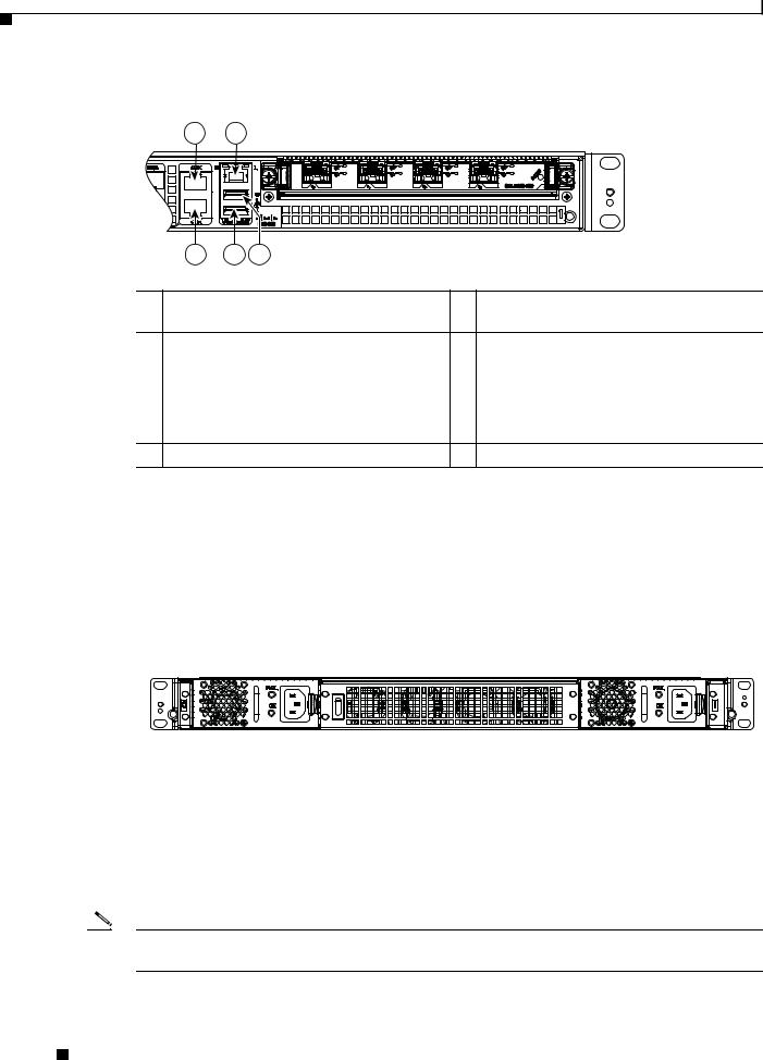
Cisco ASR 1001-X Chassis Rear View
Figure 1-4 shows the rear of the Cisco ASR 1001-X Router with four fans and two AC or DC power supplies.
Figure 1-4 Cisco ASR 1001-X Router Rear View
371076
Four internal fans draw cooling air into the chassis and across internal components to maintain an acceptable operating temperature. The fans are located in the center of the chassis. The fans are numbered from 0 to 3, right to left.
Two power supplies, either two AC power supplies or two DC power supplies are accessed from the rear of the router and are hot-swappable.
Note The Cisco ASR 1001-X Router can support two AC or two DC power supplies. Do not install mixed AC and DC power supply units in the same chassis.
Cisco ASR 1001-X Router Hardware Installation Guide
1-4 |
OL-32376-02 |
|
|

Chapter 1 Cisco ASR 1001-X Router Overview
Field-Replaceable Units for the Cisco ASR 1001-X Router
Cisco ASR 1001-X SPA GE and TE Ports
The 10 GE SFP+ ports are indicated in the front bezel with orange highlights, and the GE SFP ports are indicated with yellow highlights. Figure 1-5 shows the port numbering for the 10 GE SFP+ and GE SFP ports.
Figure 1-5 10 GE SFP+ and GE SFP Port Numbering
2 |
4 |
6 |
8 |
|
|
|
371320 |
1 |
3 |
5 |
7 |
1 |
10 GE SFP+ Port 0/0/0 |
5 |
GE SFP Port 0/0/2 |
|
|
|
|
2 |
10 GE SFP+ Port 0/0/1 |
6 |
GE SFP Port 0/0/3 |
|
|
|
|
3 |
GE SFP Port 0/0/0 |
7 |
GE SFP Port 0/0/4 |
|
|
|
|
4 |
GE SFP Port 0/0/1 |
8 |
GE SFP Port 0/0/5 |
|
|
|
|
Field-Replaceable Units for the Cisco ASR 1001-X Router
The Cisco ASR 1001-X Router has a number of FRUs. These include:
•SPAs
•Dual In-line Memory Modules (DIMMs)
•NIMs
•SSD and SSD NIM assembly
•USB flash or secure token memory stick
•AC and DC power supplies
For more information, see “Removing and Replacing FRUs from the Cisco ASR 1001-X Router”.
Cisco ASR 1001-X Router Hardware Installation Guide
|
OL-32376-02 |
1-5 |
|
|
|

Chapter 1 Cisco ASR 1001-X Router Overview
Cisco Product Identification Standard
Cisco Product Identification Standard
This section describes the Cisco products and services product identification standard. This feature provides you with the ability to effectively integrate and manage Cisco products in your network and business operations.
Unique Device Identifier
The Unique Device Identifier (UDI) is the Cisco product identification standard for hardware products. A product identification standard removes barriers to enterprise automation and can help you reduce operating expenses.
The UDI provides a consistent electronic, physical, and associated business-to-business information product identification standard.
The UDI is a combination of five data elements. Table 1-1 lists the UDI elements.
Table 1-1 |
UDI Elements |
|
|
|
|
|
|
|
|
|
|
Electronic |
Physical |
|
UDI Data Element |
Visibility |
Visibility |
Description |
|
|
|
|
|
|
PID |
|
Yes |
Yes |
Product ID, also known as product name, model |
|
|
|
|
name, product number |
|
|
|
|
|
VID |
|
Yes |
Yes |
Version ID |
|
|
|
|
|
SN |
|
Yes |
Yes |
Serial number, the unique instance of the PID |
|
|
|
|
|
Entity Name |
|
Yes |
— |
Type, such as chassis, slot, or power supply |
|
|
|
|
|
Product Description |
Yes |
— |
Additional product information |
|
|
|
|
|
|
The combination of serial number and product ID (PID) is unique and consistent across all Cisco products. The PID that is coded on hardware is called a base product identifier.
Additional orderable PIDs can be associated to a base PID. For instance, an orderable PID may describe a packaging configuration for a product or a bundled group of products sold, tested, and shipped together. Specific unique device identifier (UDI) benefits include the following:
•Identifies:
–Individual Cisco products in your networks
–PIDs and serial numbers for service and replaceable products
–Version IDs (VIDs) for product version visibility
•Facilitates discovery of products subject to recall or upgrade
•Enhances inventory automation of Cisco products
The Cisco product identification standard provides the following features:
•Version visibility—Cisco continuously improves products through feature additions. Product changes are indicated by incrementing the VID, which provides version visibility to help you understand and manage product changes. VID management ensures consistency of changes from product to product.
Cisco ASR 1001-X Router Hardware Installation Guide
1-6 |
OL-32376-02 |
|
|

Chapter 1 Cisco ASR 1001-X Router Overview
SPA Slot Numbering
•Operating expense reduction—Cisco UDIs provide accurate and detailed network inventory information; identifying each Cisco product in a network element through a standard interface. Cisco operating systems can view and use this data, allowing you to automate your electronic inventory.
•Consistency across product layers—The UDIs are embedded in the hardware products and cannot be overwritten. Operating and management systems discover UDIs through standard interfaces and display UDIs in standard outputs. Standard interfaces include the IETF standard ENTITY-MIB.
Example 1-1 show diag subslot eeprom Command
The show diag subslot eeprom command displays the PID, VID, PCB serial number, hardware revision, and other such information.
The following is sample output from the show diag subslot eeprom command:
Router# show diag subslot 0/0 eeprom
MIDPLANE EEPROM |
data: |
|
Product |
Identifier (PID) |
: ASR1001-X |
Version |
Identifier (VID) |
: V00 |
PCB Serial Number |
: JAE17450EUV |
|
Top Assy. Part Number |
: 68-4703-06 |
|
Hardware Revision |
: 0.1 |
|
Asset ID |
|
: |
CLEI Code |
: CMMP410DRA |
|
Note Common Language Equipment Identification (CLEI) code is a ten-digit character code that identifies a specific product. A CLEI code is applied to each part within a Cisco ASR1001-X Router as they are programmed in manufacturing for shipment to customers.
Example 1-2 show license udi Command
The show license udi command displays UDI information.
The following is sample output from the show license udi command:
Router# show license udi
SlotID PID SN UDI
--------------------------------------------------------------------------------
*6 ASR1001-X JAE17190302 ASR1001-X:JAE17190302
Note For complete information on the product identification standard, see http://www.cisco.com/go/udi/
SPA Slot Numbering
A shared port adapter (SPA) is a modular type of port adapter that can be inserted into a subslot to provide network connectivity and increased interface port density. The Cisco ASR 1001-X Router supports one flexible integrated NIM slot and one half-height SPA bay.
Figure 1-6 shows slot numbering on the Cisco ASR 1001-X Router.
Cisco ASR 1001-X Router Hardware Installation Guide
|
OL-32376-02 |
1-7 |
|
|
|

Chapter 1 Cisco ASR 1001-X Router Overview
Serial Number and PID/VID Label Location
Figure 1-6 Cisco ASR 1001-X Router Slot Numbering
|
3 |
2 |
|
|
371079 |
|
1 |
|
1 |
Subslot 0/0 connected to the built-in 6x1GE |
3 Slot 0/2 connected to the NIM module |
|
SPA, and 2x10GE SFP+ interfaces on the |
|
|
mainboard |
|
2 |
Slot 0/1 connected to the half-height SPA slot |
- |
Serial Number and PID/VID Label Location
Figure 1-7 shows a Cisco ASR 1001-X Router chassis along with the location of the serial number and the PID/VID label.
Figure 1-7 Cisco ASR 1001-X Router Serial Number and PID/VID Label Location
SN: XXXNNNNXXX
PID / VID


 371135
IDV/DIP
Cisco ASR 1001-X Router Hardware Installation Guide
1-8 |
OL-32376-02 |
|
|

C H A P T E R 2
Cisco ASR 1001-X Router Supported Hardware
Components
This chapter contains information about the supported hardware components on the Cisco ASR 1001-X Router, and contains the following sections:
•Supported Hardware Components, page 2-1
•Supported Half-Height SPAs, page 2-2
•Supported Small Form-Factor Pluggable (SFP and SFP+) Transceivers, page 2-3
•Supported NIMs, page 2-4
•Cisco ASR 1001-X Router Power Supplies, page 2-5
Supported Hardware Components
Table 2-1 lists the hardware components supported on the Cisco ASR 1001-X Router.
Table 2-1 |
Supported Hardware Components |
|
|
|
|
Component |
|
Description |
|
|
|
Chassis |
|
1 RU form factor |
|
|
|
Ethernet Ports |
|
Six built-in Gigabit Ethernet and two built-in 10-Gigabit Ethernet ports |
|
|
|
ESP |
|
A nonmodular, fixed ESP with a default throughput of 2.5 Gbps, which |
|
|
is upgradable with a software-activated performance license of 5 Gbps, |
|
|
10 Gbps, or 20 Gbps. |
|
|
|
Route Processor |
Single integrated route processor |
|
|
|
|
SIP |
|
Integrated SIP |
|
|
|
SPA Slots |
|
1 half-height (HH) SPA bay |
|
|
|
NIM Slots |
|
1 |
|
|
|
USB Slots |
|
2 |
|
|
|
Cisco ASR 1001-X Router Hardware Installation Guide
|
OL-32376-02 |
2-1 |
|
|
|

Chapter 2 Cisco ASR 1001-X Router Supported Hardware Components
Supported Half-Height SPAs
Supported Half-Height SPAs
Table 2-1 lists the supported half-height SPAs on the Cisco ASR 1001-X Router.Supported Half-Height SPAs
|
|
|
|
Table 2-2 |
Supported Half-Height SPAs |
|
|
|
|
|
|
|
|
|
|
|
|
|
|
|
|
PID |
|
Description |
|
|
|
|
|
|
|
|
|
||
|
|
|
|
SPA-1X10GE-L-V2 |
Cisco 1-Port 10GE LAN-PHY |
|
||
|
|
|
|
|
|
|
||
|
|
|
|
SPA-1XCHSTM1/OC3 |
1-port Channelized STM-1/OC-3c to DS0 |
|
|
|
|
|
|
|
|
|
|
||
|
|
|
|
SPA-1XOC12-POS |
1-port OC12/STM4 POS |
|
|
|
|
|
|
|
|
|
|
||
|
|
|
|
SPA-2XOC12-POS |
2-port OC12/STM4 POS |
|
|
|
|
|
|
|
|
|
|
||
|
|
|
|
SPA-4XOC12-POS |
4-port OC-12/STM-4 POS |
|
|
|
|
|
|
|
|
|
|
||
|
|
|
|
SPA-8XOC12-POS |
8-port OC12/STM4 |
|
|
|
|
|
|
|
|
|
|
||
|
|
|
|
SPA-1XOC3-ATM-V2 |
1-port OC-3c/STM-1 ATM |
|
|
|
|
|
|
|
|
|
|
||
|
|
|
|
SPA-2X1GE-V2 |
Cisco 2-Port Gigabit Ethernet |
|
|
|
|
|
|
|
|
|
|
||
|
|
|
|
SPA-2XCT3/DS0 |
2-port Channelized T3 to DS0 |
|
|
|
|
|
|
|
|
|
|
||
|
|
|
|
SPA-2XOC3-POS |
2-port OC3/STM1 POS |
|
|
|
|
|
|
|
|
|
|
||
|
|
|
|
SPA-8XOC3-POS |
8-port OC-3/STM-1 POS |
|
|
|
|
|
|
|
|
|
|
||
|
|
|
|
SPA-1XOC48POS/RPR |
1-port OC48/STM16 POS/RPR |
|
|
|
|
|
|
|
|
|
|
||
|
|
|
|
SPA-2XOC48POS/RPR |
2-port OC48/STM16 POS/RPR |
|
|
|
|
|
|
|
|
|
|
|
|
|
|
|
|
SPA-2XT3/E3 |
|
2-port Clear Channel T3/E3 |
|
|
|
|
|
|
|
|
|
||
|
|
|
|
SPA-3XOC3-ATM-V2 |
3-port OC-3c/STM-1 ATM |
|
|
|
|
|
|
|
|
|
|
||
|
|
|
|
SPA-4X1FE-TX-V2 |
Cisco 4-Port Fast Ethernet (TX) |
|
|
|
|
|
|
|
|
|
|
||
|
|
|
|
SPA-4XCT3/DS0 |
4-port Channelized T3 to DS0 |
|
|
|
|
|
|
|
|
|
|
||
|
|
|
|
SPA-4XOC3-POS |
4-port OC3/STM1 POS |
|
|
|
|
|
|
|
|
|
|
||
|
|
|
|
SPA-4XOC48POS/RPR |
4-port OC48/STM16 POS/RPR Shared Port |
|
|
|
|
|
|
|
|
|
Adapters |
|
|
|
|
|
|
|
|
|
||
|
|
|
|
SPA-OC192POS-XFP |
1-port OC192/STM64 POS/RPR XFP Optics |
|
|
|
|
|
|
|
|
|
|
||
|
|
|
|
SPA-4XT-SERIAL |
Cisco 4-port serial SPA |
|
|
|
|
|
|
|
|
|
|
|
|
|
|
|
|
SPA-4XT3/E3 |
|
4-port Clear Channel T3/E3 |
|
|
|
|
|
|
|
|
|
||
|
|
|
|
SPA-5X1GE-V2 |
Cisco 5-Port Gigabit Ethernet |
|
|
|
|
|
|
|
|
|
|
||
|
|
|
|
SPA-8X1FE-TX-V2 |
Cisco 8-Port Fast Ethernet (TX) |
|
|
|
|
|
|
|
|
|
|
||
|
|
|
|
SPA-8X1GE-V2 |
Cisco 8-Port Gigabit Ethernet |
|
|
|
|
|
|
|
|
|
|
||
|
|
|
|
SPA-8XCHT1/E1 |
8-port Channelized T1/E1 to DS0 |
|
|
|
|
|
|
|
|
|
|
||
|
|
|
|
SPA-1XOC12-ATM-V2 |
1-port OC12 STM |
|
|
|
|
|
|
|
|
|
|
|
|
|
|
|
|
SPA-DSP |
|
Digital Signal Processor SPA |
|
|
|
|
|
|
|
|
|
||
|
|
|
|
SPA-1X10GE-WL-V2 |
Cisco 1-port 10GE LAN/WAN-PHY |
|
|
|
|
|
|
|
|
|
|
||
|
|
|
|
SPA-2CHT3-CE-ATM |
2-Port Channelized T3/E3 ATM and Circuit |
|
|
|
|
|
|
|
|
|
Emulation SPA |
|
|
|
|
|
|
|
|
|
|
|
|
|
|
Cisco ASR 1001-X Router Hardware Installation Guide |
|
|
|
||
|
|
|
|
|
|
|||
|
|
|
|
|
|
|
|
|
|
2-2 |
|
|
|
|
OL-32376-02 |
|
|
|
|
|
|
|
|
|||

Chapter 2 Cisco ASR 1001-X Router Supported Hardware Components
Supported Small Form-Factor Pluggable (SFP and SFP+) Transceivers
Table 2-2 |
Supported Half-Height SPAs (continued) |
|
|
|
|
PID |
|
Description |
|
|
|
SPA-4XOC3-POS-V2 |
4-port OC-3/STM-1 POS |
|
|
|
|
SPA-2X1GE-SYNCE1 |
Cisco Synchronous Ethernet SPA |
|
SPA-8XT3/E3 |
|
Cisco 8-Port Clear Channel T3/E3 Shared Port |
|
|
Adapter |
|
|
|
SPA-24CHT1-CE-ATM |
Cisco 24 Port T1/E1/J1 Circuit Emulation SPA |
|
|
|
|
SPA-1CHSTM1/OC3V2 |
1-Port Channelized OC-3/STM-1 SPA, Version 2 |
|
|
|
|
SPA-1XOC12-POS-V2 |
1-Port OC-12C/STM-4 Multirate POS SPA |
|
|
|
(license) |
|
|
|
SPA-2XOC3-POS-V2 |
2-Port OC-3C/STM-1 POS SPA (license) |
|
|
|
|
SPA-2XCT3/DS0-V2 |
2-Port Channelized T3 SPA, Version 2 |
|
|
|
|
SPA-4XCT3/DS0-V2 |
4-Port Channelized T3 SPA, Version 2 |
|
|
|
|
SPA-2XT3/E3-V2 |
2-Port Clear Channel T3/E3 SPA, Version 2 |
|
|
|
|
SPA-4XT3/E3-V2 |
4-Port Clear Channel T3/E3 SPA, Version 2 |
|
|
|
|
SPA-8XCHT1/E1-V2 |
8-Port Channelized T1/E1 SPA, Version 2 |
|
|
|
|
1.There is a limitation for clock switchover scenarios between the Cisco ASR 1001-X Router's built-in ports and the SPA-2X1GE-SYNCE. All the other functionalities on the SPA-2X1GE-SYNCE are supported.
Supported Small Form-Factor Pluggable (SFP and SFP+)
Transceivers
Table 2-3 and Table 2-4 list the supported SFP optics and SFP copper interfaces on the Cisco ASR 1001-X Router.
|
|
Table 2-3 |
Supported 1 GE SFP Optics and SFP Copper Interfaces |
||||
|
|
|
|
|
|
||
|
|
PID |
|
Description |
|
||
|
|
|
|
|
|
||
|
|
SFP-GE-S |
|
1000BASE-SX SFP (DOM) |
|
||
|
|
|
|
|
|
||
|
|
GLC-SX-MMD |
|
1000BASE-SX SFP transceiver module, MMF, |
|
||
|
|
|
|
850nm, DOM |
|
||
|
|
|
|
|
|
||
|
|
SFP-GE-L |
|
1000BASE-LX/LH SFP (DOM) |
|
||
|
|
|
|
|
|
||
|
|
GLC-LH-SMD |
|
1000BASE-LX/LH SFP transceiver module, |
|
||
|
|
|
|
MMF/SMF, 1310nm, DOM |
|
||
|
|
|
|
|
|
||
|
|
SFP-GE-Z |
|
1000BASE-ZX Gigabit Ethernet SFP (DOM) |
|
||
|
|
|
|
|
|
||
|
|
SFP-GE-T |
|
1000BASE-T SFP (NEBS 3 ESD) |
|
||
|
|
|
|
|
|
||
|
|
GLC-BX-U |
|
1000BASE-BX SFP, 1310NM |
|
||
|
|
|
|
|
|
||
|
|
GLC-BX-D |
|
1000BASE-BX SFP, 1490NM |
|
||
|
|
|
|
|
|
||
|
|
GLC-TE |
|
1000BASE-T SFP transceiver module for |
|
||
|
|
|
|
category 5 copper wire |
|
||
|
|
|
|
|
|
||
|
|
GLC-SX-MM |
|
GE SFP, LC connector SX transceiver |
|
||
|
|
|
|
|
|
|
|
|
|
|
Cisco ASR 1001-X Router Hardware Installation Guide |
|
|
|
|
|
|
|
|
||||
|
|
|
|
|
|
|
|
|
OL-32376-02 |
|
|
|
2-3 |
|
|
|
|
|
|
|
|||

Chapter 2 Cisco ASR 1001-X Router Supported Hardware Components
Supported NIMs
Table 2-3 |
Supported 1 GE SFP Optics and SFP Copper Interfaces |
|
|
|
|
PID |
|
Description |
|
|
|
GLC-LH-SM |
|
GE SFP, LC connector LX/LH transceiver |
|
|
|
GLC-EX-SMD |
|
GE SFP, LC Connector, EX transceiver |
|
|
|
GLC-ZX-SMD |
|
1000BASE-ZX SFP transceiver module, SMF, |
|
|
1550nm, DOM |
|
|
|
DWDM-SFP |
|
1000BASE DWDM |
|
|
|
CWDM-SFP |
|
1000BASE CWDM |
|
|
|
Table 2-4 |
Supported 10 GE SFP Optics and SFP Copper Interface |
|
|
|
|
PID |
|
Description |
|
|
|
SFP-10G-SR |
|
10GBASE-SR SFP+ Module for MMF |
|
|
|
SFP-10G-SR-X |
|
10GBASE-SR SFP Module for Extended Temp |
|
|
range |
|
|
|
SFP-10G-LR |
|
10GBASE-LR SFP+ Module for SMF |
|
|
|
SFP-10G-LR-X |
|
10GBASE-LR SFP Module for Extended Temp |
|
|
range |
|
|
|
SFP-10G-ER |
|
10GBASE-ER SFP+ Module for SMF |
|
|
|
SFP-10G-ZR |
|
10GBASE-ZR SFP+ Module for SMF |
|
|
|
Supported NIMs
The Cisco ASR 1001-X Router supports the following NIM form factors:
• |
NIM-SSD |
• |
NIM-T1/E1 |
NIM-SSD
Table 2-5 lists the supported NIM with Solid State Disk (SSD) on the Cisco ASR 1001-X Router:
Table 2-5 |
Supported NIM SSDs |
|
|
|
|
Part Number |
|
Description |
|
|
|
NIM-SSD |
|
NIM Carrier Card for SSD drives |
|
|
|
SSD-SATA-200G |
200 GB, SATA Solid State Disk |
|
|
|
|
SSD-SATA-400G |
400 GB, SATA Solid State Disk |
|
|
|
|
Cisco ASR 1001-X Router Hardware Installation Guide
2-4 |
OL-32376-02 |
|
|
Loading...