


Deployment Guide
Cisco Catalyst 9115 and 9117
Series Access Points
© 2019 Cisco and/or its affiliates. All rights reserved. This document is Cisco Public Information. |
Page 1 of 38 |

Contents |
|
Revision history............................................................................................................ |
Error! Bookmark not defined. |
Wi-Fi 6 primer – how is it different from 802.11ac? .............................................................................................. |
3 |
Choosing the right access point ............................................................................................................................ |
6 |
Models .................................................................................................................................................................. |
6 |
Access point physical hardware and mounting options...................................................................................... |
7 |
Channel rail adapters .......................................................................................................................................... |
11 |
Wall mounting the access point .......................................................................................................................... |
12 |
Changing the color of an access point ................................................................................................................ |
13 |
Unique installations............................................................................................................................................... |
14 |
Clean rooms (healthcare).................................................................................................................................... |
14 |
Above the ceiling tiles ......................................................................................................................................... |
15 |
Stadium and harsh environments ....................................................................................................................... |
17 |
Areas with high vibration ..................................................................................................................................... |
18 |
Warehouse and factory environments ................................................................................................................ |
18 |
Ethernet cable recommendation ......................................................................................................................... |
20 |
Antenna cable recommendation ......................................................................................................................... |
20 |
Access point spacing recommendations ............................................................................................................. |
21 |
Installations in IDF closets (telecommunications or other electrical equipment) ................................................. |
21 |
Installations inside and around elevators ............................................................................................................ |
21 |
External antenna options and patterns................................................................................................................ |
22 |
For use with the Cisco Catalyst 9115E Access Point.......................................................................................... |
22 |
Cisco Catalyst 9115I internal antenna model...................................................................................................... |
29 |
Understanding external antenna deployments ................................................................................................... |
34 |
Power over Ethernet .............................................................................................................................................. |
36 |
General considerations regarding access points............................................................................................... |
37 |
© 2019 Cisco and/or its affiliates. All rights reserved. This document is Cisco Public Information. |
Page 2 of 38 |
This document is intended for trained and experienced technical personnel familiar with the existing Cisco Wireless Networking Group (WNG) product line and features.
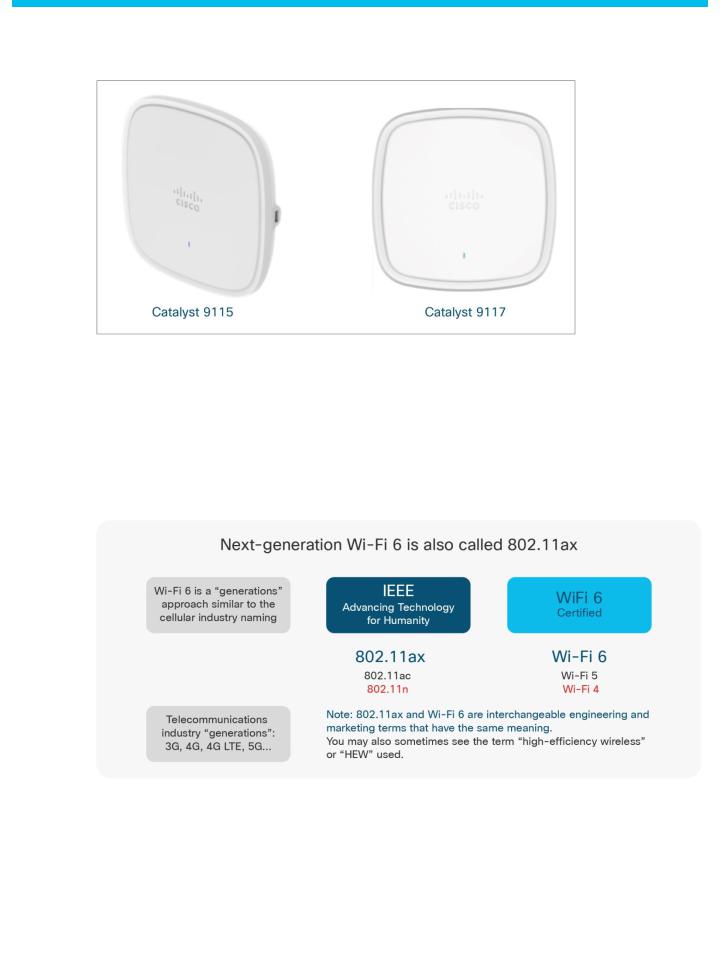
Wi-Fi 6 primer – how is it different from 802.11ac?
The Cisco® Catalyst® 9115 and 9117 Series Access Points are built upon the emerging standard known as Wi-Fi 6. This next-generation Wi-Fi is all about high-efficiency wireless (getting the most out of every packet that is on the air) in a way that improves the user experience.
Figure 1. Next-generation Wi-Fi 6
© 2019 Cisco and/or its affiliates. All rights reserved. This document is Cisco Public Information. |
Page 3 of 38 |
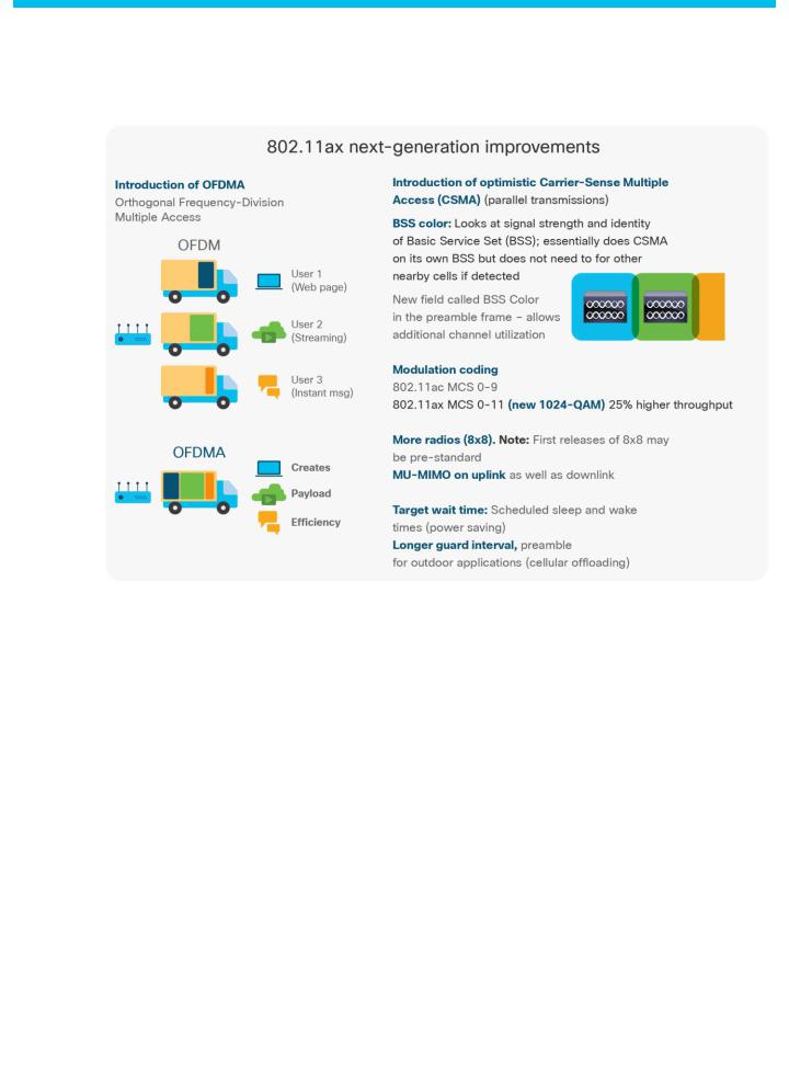
Figure 2. 802.11ax improvements
© 2019 Cisco and/or its affiliates. All rights reserved. This document is Cisco Public Information. |
Page 4 of 38 |

Figure 3. Differences between 802.11ac and 802.11ax
© 2019 Cisco and/or its affiliates. All rights reserved. This document is Cisco Public Information. |
Page 5 of 38 |
Choosing the right access point
Models
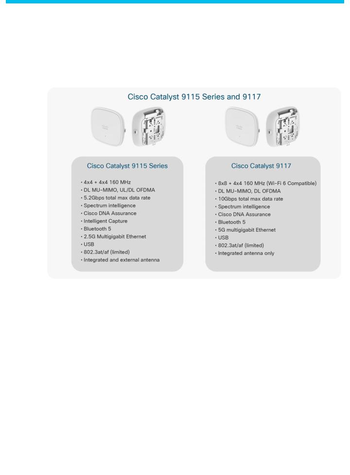
Figure 4. Features of the Cisco Catalyst 9115 and 91117AX Series Access Points
The Cisco Catalyst 9115 Series has models supporting internal (AXI) and external (AXE) antenna options. The 9115E model is ideal in areas where external antennas are already deployed or where a directional antenna is desired.
The internal antenna versions (9115I and 9117I) are ideal for carpeted areas where ceiling installations are desirable.
© 2019 Cisco and/or its affiliates. All rights reserved. This document is Cisco Public Information. |
Page 6 of 38 |
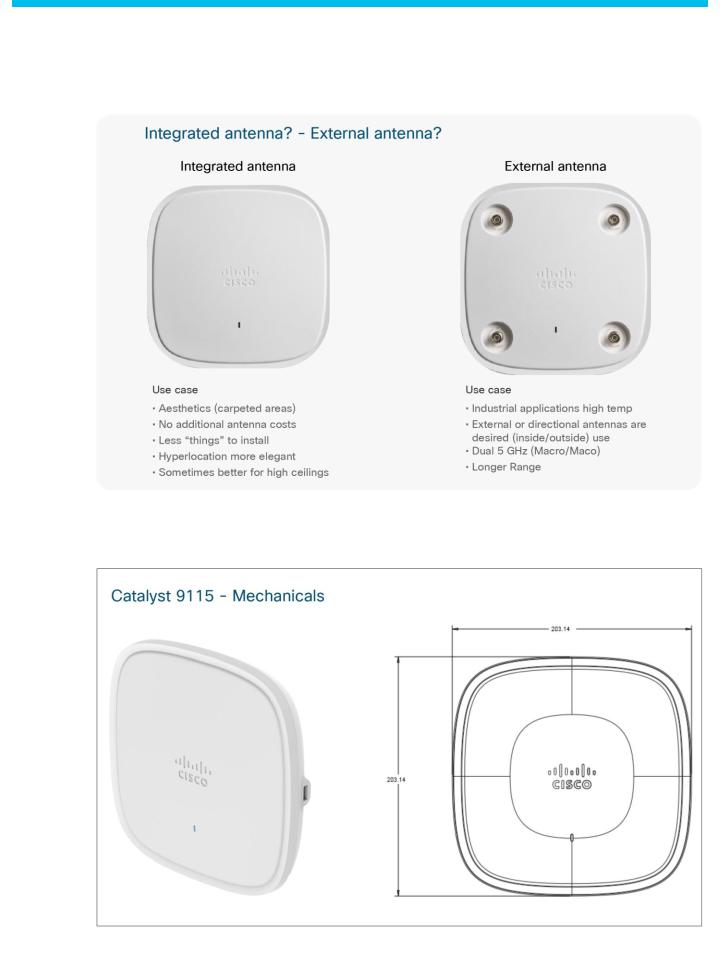
Figure 5. Choosing an integrated antenna or an external antenna
Access point physical hardware and mounting options
Figure 6. Cisco Catalyst 9115 Series mechanicals
© 2019 Cisco and/or its affiliates. All rights reserved. This document is Cisco Public Information. |
Page 7 of 38 |
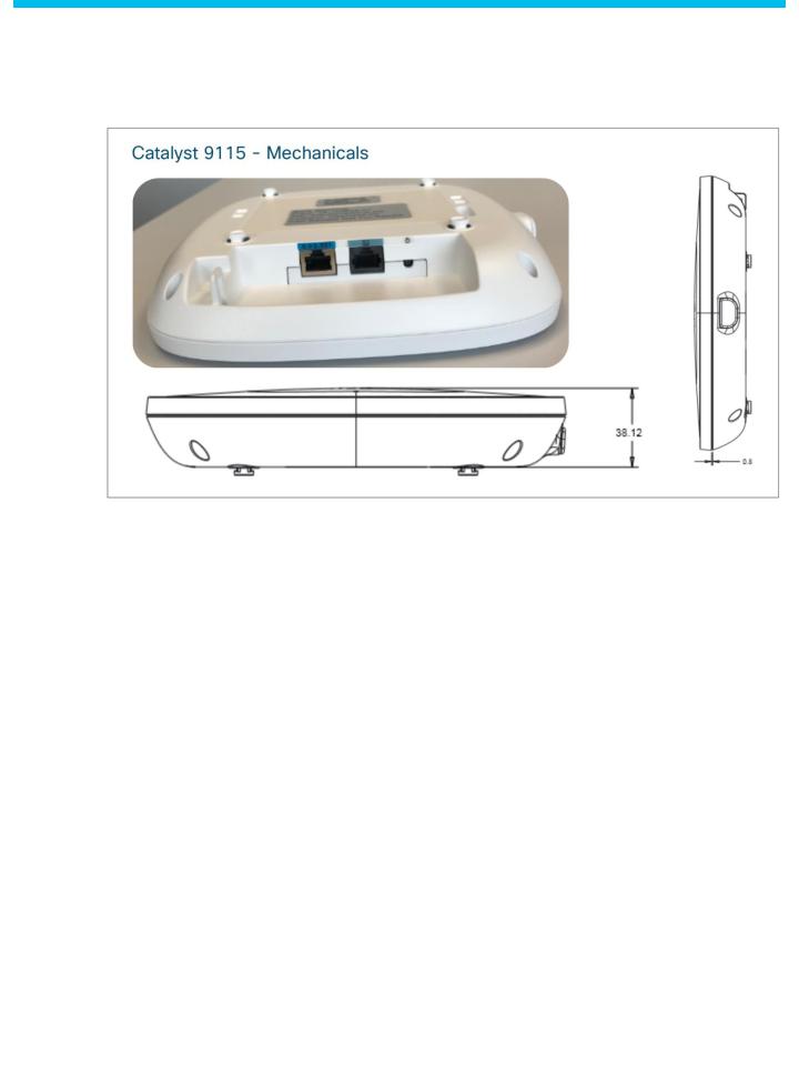
Figure 7. Cisco Catalyst 9115 Series mechanicals (continued)
© 2019 Cisco and/or its affiliates. All rights reserved. This document is Cisco Public Information. |
Page 8 of 38 |
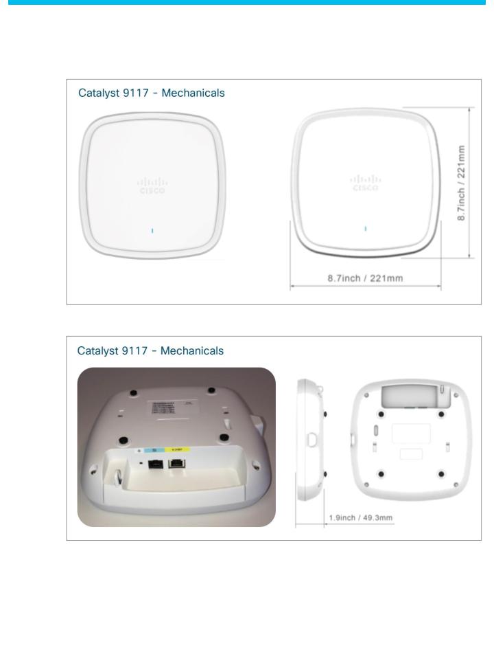
Figure 8. Cisco Catalyst 9117 Series mechanicals
Figure 9. Cisco Catalyst 9117 Series mechanicals (continued)
Many different installation options are available, depending on the requirements of the customer. Brackets are available from Cisco as well as third-party companies. During the ordering process, the customer may choose one of two brackets (but not both). Each bracket is a zero-dollar ($0) option at the time of configuration. If the customer does not choose a bracket, the default is AIR-AP-BRACKET-1, which is the most popular for ceiling installations. The other choice is a universal bracket that carries part number AIR-AP-BRACKET-2 (Figure 10).
© 2019 Cisco and/or its affiliates. All rights reserved. This document is Cisco Public Information. |
Page 9 of 38 |
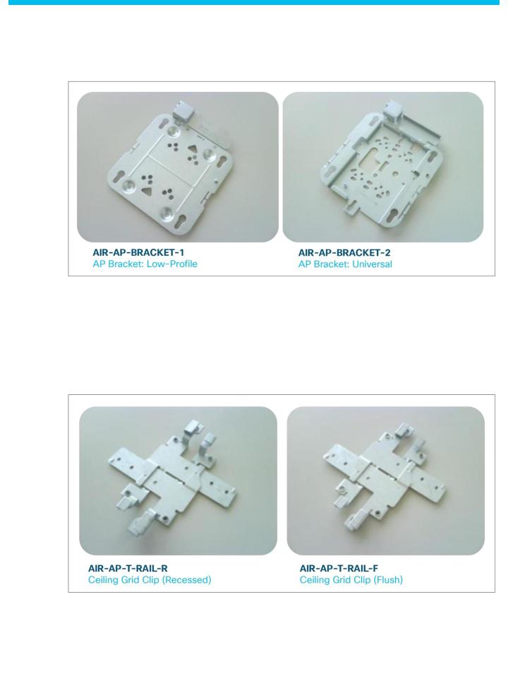
Figure 10. Brackets available for mounting access points
If the access point will be mounted directly to a ceiling on the gridwork, the AIR-AP-BRACKET-1 mounts flush and has the lowest profile. However, if the access point will be mounted to an electrical box or other wiring fixture, or inside a NEMA-rated enclosure or perhaps wall mounted, the AIR-AP-BRACKET-2 is a better choice. The extra space in the bracket allows for wiring, and the extra holes line up with many popular electrical boxes. When the bracket is mounted to the ceiling gridwork, the clips used will depend on whether the ceiling tiles are recessed. Two different styles of ceiling clips, recessed and flush rails, are available (Figure 11).
Figure 11. Ceiling clips
© 2019 Cisco and/or its affiliates. All rights reserved. This document is Cisco Public Information. |
Page 10 of 38 |
Channel rail adapters
When mounting access points to ceiling channel rails such as the ones shown in Figure 12, an optional channel adapter is used: AIR-CHNL-ADAPTER. It comes in a 2-pack and attaches to the ceiling grid clip shown in Figure 11. Refer to Figures 13 and 14.
Figure 12. Examples of channel rails
Figure 13. AIR-CHNL-ADAPTER (left) slides onto the rails
Figure 14. AIR-CHNL-ADAPTER mounted to rail clip (left) and finished installation (right)
© 2019 Cisco and/or its affiliates. All rights reserved. This document is Cisco Public Information. |
Page 11 of 38 |
Wall mounting the access point
When wall mounting is desired, the installer should understand that walls can be a physical obstacle to the wireless signal; therefore, 360-degree coverage may be compromised by the wall. If the wall is an outside wall and/or the goal is to send the signal in a 180-degree pattern instead, a directional antenna often referred to as a “patch” antenna may be a better choice, assuming that the external antenna access point model is used.
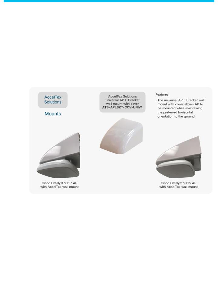
Avoid wall-mounting access points with internal antennas unless you use an optional right-angle mount (available from third-party vendors), as the internal antenna model was designed to mount to a ceiling to provide 360-degree coverage. See Figure 15.
Figure 15. Wall-mount options
If the access point is wall mounted in a non-ceiling orientation, the signal may penetrate the floors above and below, causing unintended coverage that could result in additional, needless roaming access when a mobility client, such as a user with a Wi-Fi phone, walks by on an adjacent floor.
© 2019 Cisco and/or its affiliates. All rights reserved. This document is Cisco Public Information. |
Page 12 of 38 |
 Loading...