


 Loading...
Cisco Video Surveillance 2630 IP Dome
User Guide
Model CIVS-IPC-2630V
Americas Headquarters
Cisco Systems, Inc. 170 West Tasman Drive
San Jose, CA 95134-1706 USA http://www.cisco.com Tel: 408 526-4000
800 553-NETS (6387) Fax: 408 527-0883
Text Part Number: OL-24130-02
NOTICE. ALL STATEMENTS, INFORMATION, AND RECOMMENDATIONS IN THIS MANUAL ARE BELIEVED TO BE ACCURATE BUT ARE PRESENTED WITHOUT WARRANTY OF ANY KIND, EXPRESS OR IMPLIED. USERS MUST TAKE FULL RESPONSIBILITY FOR THEIR APPLICATION OF ANY PRODUCTS.
THE SOFTWARE LICENSE AND LIMITED WARRANTY FOR THE ACCOMPANYING PRODUCT ARE SET FORTH IN THE INFORMATION PACKET THAT SHIPPED WITH THE PRODUCT AND ARE INCORPORATED HEREIN BY THIS REFERENCE. IF YOU ARE UNABLE TO LOCATE THE SOFTWARE LICENSE OR LIMITED WARRANTY, CONTACT YOUR CISCO REPRESENTATIVE FOR A COPY.
The Cisco implementation of TCP header compression is an adaptation of a program developed by the University of California, Berkeley (UCB) as part of UCB’s public domain version of the UNIX operating system. All rights reserved. Copyright © 1981, Regents of the University of California.
NOTWITHSTANDING ANY OTHER WARRANTY HEREIN, ALL DOCUMENT FILES AND SOFTWARE OF THESE SUPPLIERS ARE PROVIDED “AS IS” WITH ALL FAULTS. CISCO AND THE ABOVE-NAMED SUPPLIERS DISCLAIM ALL WARRANTIES, EXPRESSED OR IMPLIED, INCLUDING, WITHOUT LIMITATION, THOSE OF MERCHANTABILITY, FITNESS FOR A PARTICULAR PURPOSE AND NONINFRINGEMENT OR ARISING FROM A COURSE OF DEALING, USAGE, OR TRADE PRACTICE.
IN NO EVENT SHALL CISCO OR ITS SUPPLIERS BE LIABLE FOR ANY INDIRECT, SPECIAL, CONSEQUENTIAL, OR INCIDENTAL DAMAGES, INCLUDING, WITHOUT LIMITATION, LOST PROFITS OR LOSS OR DAMAGE TO DATA ARISING OUT OF THE USE OR INABILITY TO USE THIS MANUAL, EVEN IF CISCO OR ITS SUPPLIERS HAVE BEEN ADVISED OF THE POSSIBILITY OF SUCH DAMAGES.
CCDE, CCENT, CCSI, Cisco Eos, Cisco HealthPresence, Cisco Ironport, the Cisco logo, Cisco Lumin, Cisco Nexus, Cisco Nurse Connect, Cisco Stackpower, Cisco StadiumVision, Cisco TelePresence, Cisco Unified Computing System, Cisco WebEx, DCE, Flip Channels, Flip for Good, Flip Mino, Flip Video, Flip Video (Design), Flipshare (Design), Flip Ultra, and Welcome to the Human Network are trademarks; Changing the Way We Work, Live, Play, and Learn, Cisco Store, and Flip Gift Card are service marks; and Access Registrar, Aironet, AsyncOS, Bringing the Meeting To You, Catalyst, CCDA, CCDP, CCIE, CCIP, CCNA, CCNP, CCSP, CCVP, Cisco, the Cisco Certified Internetwork Expert logo, Cisco IOS, Cisco Press, Cisco Systems, Cisco Systems Capital, the Cisco Systems logo, Cisco Unity, Collaboration Without Limitation, EtherFast, EtherSwitch, Event Center, Fast Step, Follow Me Browsing, FormShare, GigaDrive, HomeLink, Internet Quotient, IOS, iPhone, iQuick Study, IronPort, the IronPort logo, LightStream, Linksys, MediaTone, MeetingPlace, MeetingPlace Chime Sound, MGX, Networkers, Networking Academy, Network Registrar, PCNow, PIX, PowerPanels, ProConnect, ScriptShare, SenderBase, SMARTnet, Spectrum Expert, StackWise, The Fastest Way to Increase Your Internet Quotient, TransPath, WebEx, and the WebEx logo are registered trademarks of Cisco Systems, Inc. and/or its affiliates in the United States and certain other countries.
All other trademarks mentioned in this document or website are the property of their respective owners. The use of the word partner does not imply a partnership relationship between Cisco and any other company. (0907R)
Cisco Video Surveillance 2630 IP Dome User Guide
Copyright © 2010 Cisco Systems, Inc. All rights reserved.

C O N T E N T S
|
|
Preface |
vii |
|
|
|
|
|
|
|
|
|
|
Overview |
1-vii |
|
|
|
|
|
|
||
|
|
Organization |
1-vii |
|
|
|
|
|
|||
|
|
Obtaining Documentation, Obtaining Support, and Security Guidelines 1-vii |
|||||||||
|
|
Overview |
|
|
|
|
|
|
|
|
|
C H A P T E R |
1 |
1-1 |
|
|
|
|
|
|
|
||
|
|
Features |
1-1 |
|
|
|
|
|
|
|
|
|
|
IP Camera Overview |
1-2 |
|
|
|
|
||||
|
|
Physical Details |
1-3 |
|
|
|
|
||||
|
|
Package Contents |
1-6 |
|
|
|
|||||
|
|
Getting Started |
|
|
|
|
|
|
|
||
C H A P T E R |
2 |
2-1 |
|
|
|
|
|
|
|||
|
|
Before You Begin |
2-1 |
|
|
|
|
|
|||
|
|
Installing the Cisco Video Surveillance 2630 IP Dome 2-2 |
|||||||||
|
|
Preparing for Installation |
2-2 |
|
|
||||||
|
|
Mounting with a Conduit Base |
2-4 |
|
|||||||
|
|
Mounting with a Pendant |
2-9 |
|
|
||||||
|
|
Performing the Initial Setup of the IP Camera 2-14 |
|||||||||
|
|
Accessing the IP Camera Windows |
2-16 |
|
|||||||
|
|
Adjusting the Video Image |
2-17 |
|
|
||||||
|
|
Powering the IP Camera On or Off |
2-19 |
|
|||||||
|
|
Resetting the IP Camera |
2-19 |
|
|
|
|||||
|
|
Cleaning the IP Camera |
2-19 |
|
|
|
|||||
|
|
Configuring and Managing the IP Camera |
|
||||||||
C H A P T E R |
3 |
3-1 |
|||||||||
|
|
Configuration Overview |
3-1 |
|
|
|
|||||
|
|
Navigating the Configuration Windows |
3-4 |
||||||||
|
|
Setup Windows |
3-5 |
|
|
|
|
|
|||
|
|
Basic Setup Window |
3-5 |
|
|
|
|||||
|
|
Advanced Setup Window |
3-7 |
|
|
||||||
|
|
IP Filter Window |
3-10 |
|
|
|
|||||
|
|
EAPOL Window |
3-11 |
|
|
|
|||||
|
Administration Windows |
3-12 |
|
|
|
|
|
Cisco Video Surveillance 2630 IP Dome User Guide |
|
|
|
|
|
|
|||
|
|
|
|
|
|
|
OL-24130-02 |
|
|
iii |
|
|
|
|
|

Contents
Users Window |
3-12 |
|
Maintenance Window 3-14 |
||
Firmware Window |
3-15 |
|
Audio/Video Windows |
3-16 |
|
Video Window |
3-16 |
|
Audio Window |
3-23 |
|
Privacy Region Window |
3-24 |
||
Focus/Zoom Window |
3-24 |
||
Security Windows |
3-25 |
|
|
Initialization Window |
3-25 |
||
Complexity Window |
3-26 |
||
Applications Windows |
3-27 |
||
Mail/FTP/HTTP Window |
3-27 |
||
Motion Detection Window 3-30 |
|||
Event Window |
3-31 |
|
|
|
|
SNMP Window 3-34 |
|
|
||
|
|
Alarm I/O Ports Window |
3-35 |
|
||
|
|
Status Windows |
3-36 |
|
|
|
|
|
System Window |
3-36 |
|
|
|
|
|
Audio/Video Window 3-37 |
|
|||
|
|
Network Window |
3-38 |
|
|
|
|
|
Syslog & Log Window |
3-38 |
|
||
|
|
Video Log Window |
3-44 |
|
||
|
|
Viewing Live Video |
|
|
|
|
C H A P T E R |
4 |
4-1 |
|
|
|
|
|
|
Viewing Video through the Home Window Overview |
4-1 |
|||
|
|
Home Window Overview |
4-1 |
|
||
|
|
Home Window Controls |
4-3 |
|
||
|
|
Viewing Video through Third-Party Devices or Software |
4-5 |
|||
|
|
Troubleshooting 5-1 |
|
|
|
|
C H A P T E R |
5 |
|
|
|
|
|
|
|
Using the IP Camera with Cisco VSM 1-1 |
|
|||
A P P E N D I X |
1 |
|
||||
|
|
|
|
|
|
|
I N D E X |
|
|
|
|
|
|
Cisco Video Surveillance 2630 IP Dome User Guide
|
iv |
OL-24130-02 |
|
|
|

Preface
Overview
This document, Cisco Video Surveillance 2630 IP Dome User Guide, provides information about installing, configuring, using, managing, and troubleshooting the Cisco Video Surveillance 2630 IP Dome, model CICS-IPC-2630V.
Organization
This manual is organized as follows:
Chapter 1, “Overview” |
Provides an overview of the IP camera and its features |
|
|
Chapter 2, “Getting Started” |
Provides instructions for installing and performing |
|
the initial setup of the IP camera, connecting to the IP |
|
camera so that you can configure it or view video |
|
from it, powering the IP camera on and off, resetting |
|
the IP camera, and adjusting its back focus |
|
|
Chapter 3, “Configuring and Managing the IP |
Explains how to configure, manage, and administer |
Camera” |
the IP camera through the web-based interface |
|
|
Chapter 4, “Viewing Live Video” |
Explains how to view live video from the IP camera |
|
|
Chapter 5, “Troubleshooting” |
Provides basic troubleshooting information |
|
|
Obtaining Documentation, Obtaining Support, and Security
Guidelines
For information about obtaining documentation, submitting a service request, and gathering additional information, see the monthly What’s New in Cisco Product Documentation, which also lists all new and revised Cisco technical documentation, at:
http://www.cisco.com/en/US/docs/general/whatsnew/whatsnew.html
Subscribe to the What’s New in Cisco Product Documentation as a Really Simple Syndication (RSS) feed and set content to be delivered directly to your desktop using a reader application. The RSS feeds are a free service and Cisco currently supports RSS version 2.0.
Cisco Video Surveillance 2630 IP Dome User Guide
|
OL-24130-02 |
vii |
|

Preface
Obtaining Documentation, Obtaining Support, and Security Guidelines
Cisco Video Surveillance 2630 IP Dome User Guide
|
viii |
OL-24130-02 |
|
|
|

C H A P T E R 1
Overview
This chapter provides an overview of the Cisco Video Surveillance 2630 IP dome and its features. It includes these topics:
•Features, page 1-1
•IP Camera Overview, page 1-2
Features
The Cisco Video Surveillance IP cameras offer a feature-rich digital camera solution for a video surveillance system. They provide high-quality, bandwidth-efficient video capture and transmission, with support for D1 resolution, motion-triggered viewing, H.264 encoding, and MPEG-4 encoding. The 2630 IP domes are vandal-resistant. They include a heater and fan and are designed to be mounted outdoors. Model CIVS-IPC-2630V includes a clear dome cover.
In addition, the devices provide networking and security capabilities, including multicast support, hardware-based Advanced Encryption Standard (AES), and hardware-based Data Encryption Standard/Triple Data Encryption Standard (DES/3DES) encryption.
The IP cameras include the following key features:
•Built-in H.264 encoder—An internal H.264 encoder can generate the primary or secondary video stream.
•Built-in MPEG4 encoder—An internal MPEG4 encoder can generate up to two video streams.
•Built-in MJPEG encoder—An internal MJPEG encoder can generate the primary or secondary video stream.
•Privacy Regions—Up to four user-defined masking zones that can be used to provide regions of privacy in the camera field of view. Video within privacy regions is not recorded in the camera, nor sent in the video stream.
•Day/night switch support—An IR-cut filter provides increased sensitivity in low-light conditions.
•Two-way audio communication—Audio can be encoded with the video. With the internal or optional external microphone and optional external speaker, you can communicate with people at the IP camera location while you are in a remote location and viewing images from the IP camera.
•Multi-protocol support—Support for these protocols: DHCP, FTP, HTTP, HTTPS, NTP, RTP, RTSP, SMTP, SSL/TLS, and TCP/IP.
•Web-based management—You perform ongoing administration and management of an IP camera through web-based configuration menus.
Cisco Video Surveillance 2630 IP Dome User Guide
|
OL-24130-02 |
1-1 |
|
|
|

Chapter 1 Overview
IP Camera Overview
•Motion detection—The IP cameras can detect motion in up to four designated fields of view by analyzing changes in pixels and generate an alert if motion is detected.
•Flexible scheduling—You can configure the IP cameras to respond to events that occur within a designated schedule.
•Syslog support—The IP cameras can send log data to a Syslog server.
•IP address filter—You can designate IP addresses that can access an IP camera and IP addresses that cannot access an IP camera.
•User-definable HTTP/ HTTPS port number—Allows you to define the port that is used to connect to a camera through the Internet.
•DHCP support—An IP camera can automatically obtain its IP addresses in a network in which DHCP is enabled.
•Network Time Protocol (NTP) support—Allows an IP camera to calibrate its internal clock with a local or Internet time server.
•Camera access control—You can control access to IP camera configuration windows and live video by configuring various user types and log in credentials.
•Cisco Media API—The IP cameras supports the open, standards based, Cisco Media Application Programming Interface.
IP Camera Overview
The following sections provide information about the Cisco Video Surveillance IP Camera:
•Physical Details, page 1-3
•Package Contents, page 1-6
Cisco Video Surveillance 2630 IP Dome User Guide
1-2 |
OL-24130-02 |
|
|
Chapter 1 Overview
IP Camera Overview
Physical Details
Figure 1-1 and the table that follows describe the items on the top of the 2630 IP dome.
Figure 1-1 Top of the 2630 IP Dome
|
|
1 |
|
|
2 |
|
|
3 |
6 |
5 |
4 |
1 |
Network LED (amber) |
Indicates information about the network connections as follows: |
|
|
• On—LAN connection is detected |
|
|
• Off—LAN connection is not detected |
|
|
• Blinking—Data is being transmitted or received via the LAN |
|
|
connection |
|
|
|
2 |
Power LED (green) |
Lights for approximately 1 minute when the IP camera powers up, |
|
|
then turns off. |
|
|
|
Cisco Video Surveillance 2630 IP Dome User Guide
|
OL-24130-02 |
1-3 |
|
|
|

Chapter 1 Overview
IP Camera Overview
3 |
Audio port |
Allows the connection of the audio Y cable that is provided with |
|||||
|
|
the IP camera. You can connect an optional external speaker, |
|||||
|
|
optional external microphone (with pre-amplifier), or both devices |
|||||
|
|
through this cable. |
|||||
|
|
Each device connects to the audio cable through a standard 3.5 mm |
|||||
|
|
mini phone jack. A speaker connects to the green jack, which is |
|||||
|
|
labeled “Audio Out.” A microphone connects to the pink jack, |
|||||
|
|
which is labeled “Audio In.” |
|||||
|
|
|
|
|
|
|
|
4 |
GPIO ports |
General purpose input/output (GPIO) terminal block that includes |
|||||
|
|
2 input ports (labeled DI1, DI2), 2 output ports (labeled DO1, |
|||||
|
|
DO2), and 4 ground ports (labeled GND). |
|||||
|
|
|
|
|
|
|
|
5 |
LAN port |
Accepts a twisted pair category 5 or higher network cable to |
|||||
|
|
connect the IP camera to a 10/100BASET hub, router, or switch. |
|||||
|
|
|
|
|
|
|
|
6 |
Power input |
Provides for the connection of a 24 VAC power adapter. The power |
|||||
|
|
pin-out is as follows: |
|||||
|
|
|
|
|
|
|
|
|
|
|
|
|
|
|
|
|
|
|
|
|
|
|
|
|
|
|
|
|
|
|
|
|
|
|
|
|
|
|
|
|
|
|
|
|
|
|
|
|
|
|
|
|
|
|
|
Cisco Video Surveillance 2630 IP Dome User Guide
1-4 |
OL-24130-02 |
|
|

Chapter 1 Overview
IP Camera Overview
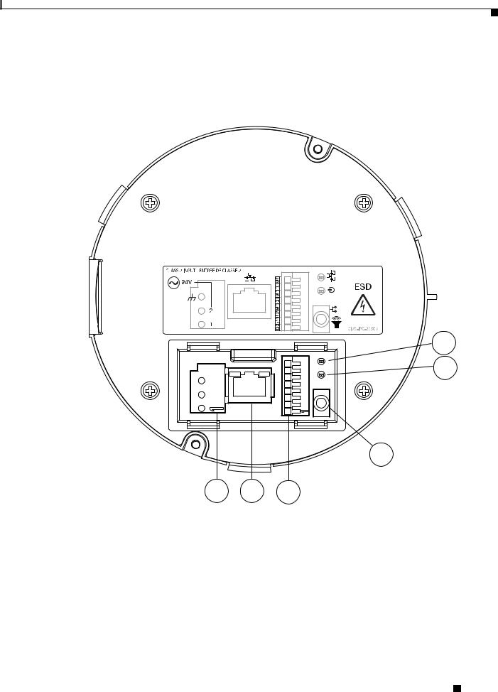
Figure 1-2 and the table that follows describe the items on the bottom of the 2630 IP dome.
Figure 1-2 Bottom of the 2630 IP Dome
1
5
4
3
2
1 |
USB port |
Reserved for future use |
|
|
|
2 |
Analog video output |
3.5 mm video jack for video output to an analog monitor. |
|
|
|
3 |
Reset button |
Recessed button that reboots the IP camera or resets it to a default |
|
|
state. You can use a pin or paper clip to depress it. It can be used |
|
|
any time that the IP camera is on and can have various effects, as |
|
|
described in the “Resetting the IP Camera” section on page 2-19. |
|
|
|
Cisco Video Surveillance 2630 IP Dome User Guide
|
OL-24130-02 |
1-5 |
|
|
|

Chapter 1 Overview
IP Camera Overview
4 |
Network LED (amber) |
Indicates information about the network connections as follows: |
|
|
• On—LAN connection is detected |
|
|
• Off—LAN connection is not detected |
|
|
• Blinking—Data is being transmitted or received via the LAN |
|
|
connection |
|
|
|
5 |
Power LED (green) |
Lights for approximately 1 minute when the camera powers up, |
|
|
then turns off. |
|
|
|
Package Contents
The the Cisco Video Surveillance IP Camera package includes these items:
•Cisco Video Surveillance 2630 IP Camera Quick Start Guide (qty. 1)
•Regulatory Compliance and Safety Information document (qty. 1)
•Camera with clear bubble (qty. 1)
•Template for mounting (qty. 1)
•0.9 mm Allen wrench for adjusting back focus (qty. 1)
•TORX security screwdriver for tamper resistant TORX head screws (qty. 1)
•8-32 x 5/16 inch screws (qty. 4)
•Security wire and screw (qty. 1)
Cisco Video Surveillance 2630 IP Dome User Guide
1-6 |
OL-24130-02 |
|
|

C H A P T E R 2
Getting Started
This chapter provides instructions for installing and performing the initial setup of the Cisco Video Surveillance IP Camera. It also describes how to access the IP camera through a web browser so that you can configure it or view video from it, and how to perform other important tasks.
This chapter includes these topics:
•Before You Begin, page 2-1
•Installing the Cisco Video Surveillance 2630 IP Dome, page 2-2
•Performing the Initial Setup of the IP Camera, page 2-14
•Accessing the IP Camera Windows, page 2-16
•Adjusting the Video Image, page 2-17
•Powering the IP Camera On or Off, page 2-19
•Resetting the IP Camera, page 2-19
•Cleaning the IP Camera, page 2-19
Before You Begin
Before you install the IP camera, review these guidelines:
•The IP camera requires a twisted pair category 5 or higher network cable and a connection to a standard 10/100BaseT hub, router, or switch.
•The IP camera requires a 24 VAC power source that is isolated from the ground (floating output).
•If you are using an external speaker, microphone, input device, or output device, you must configure additional settings after installing and performing the initial set up of the IP camera before the external device can fully operate. For detailed information about these settings, see Chapter 3, “Configuring and Managing the IP Camera.”
•If you do not connect an external device (speaker, microphone, input device, output device, or control device) when you perform the following installation procedure, you can install any of these devices later.
Warning Installation of the equipment must comply with local and national electrical codes. Statement 1074
Cisco Video Surveillance 2630 IP Dome User Guide
|
OL-24130-02 |
2-1 |
|
|
|

Chapter 2 Getting Started
Installing the Cisco Video Surveillance 2630 IP Dome
Warning The power supply must be placed indoors. Statement 331
Note If you use the IP camera outdoors, place the camera and the power supply in a suitable NEMA enclosure.
Warning This product requires short-circuit (overcurrent) protection, to be provided as part of the building installation. Install only in accordance with national and local wiring regulations. Statement 1045
Warning The plug-socket combination must be accessible at all times, because it serves as the main disconnecting device. Statement 1019
Preventing Electrostatic Discharge Damage
•Camera components can be damaged by static electricity. Not exercising the proper electrostatic discharge (ESD) precautions can result in intermittent or complete component failures, and cause the camera to malfunction.
•To minimize the potential for ESD damage:
–Before you install the IP camera, touch a metal object with your hand to release any static electricity that is in your body.
–Always use an ESD-preventive antistatic wrist strap (or ankle strap) and ensure that it makes good skin contact.
–For safety, periodically check the resistance value of the antistatic strap. The measurement should be between 1 and 10 megohm (Mohm).
In addition, follow these guidelines during installation:
•Handle camera unit by holding the edges only; avoid touching the printed circuit boards
•Never attempt to remove the printed circuit board
Installing the Cisco Video Surveillance 2630 IP Dome
The following sections describes how to install the Cisco Video Surveillance IP dome:
•Preparing for Installation, page 2-2
•Mounting with a Conduit Base, page 2-4
•Mounting with a Pendant, page 2-9
Preparing for Installation
Before you install the IP dome, follow these guidelines:
•Carefully unpack the IP dome and its components.
•Run an category 5 or higher network cable to the mounting location.
Cisco Video Surveillance 2630 IP Dome User Guide
2-2 |
OL-24130-02 |
|
|
Chapter 2 Getting Started
Installing the Cisco Video Surveillance 2630 IP Dome
•Run a power cable from a 24 VAC power adapter to the mounting location.
Use a cable gauge that is appropriate for the distance from the IP dome to the power supply (consult a qualified electrician for more information). The terminal connectors on the IP dome support gauges from 14 AWG to 24 AWG. At the end of the wire that attaches to the IP dome, strip enough cable housing to allow each wire to be stripped to 1/4 inch (6.25 mm).
Note To achieve IP66 rated protection for the IP dome when mounting outdoors, you must use the conduit base (CIVS-IPCA-1006=) or Pendant Cap (CIVS-IPCA-1010=) mounting accessory.
•If you will connect an external speaker, microphone, or both to the IP dome, run audio cable from each device to the mounting location.
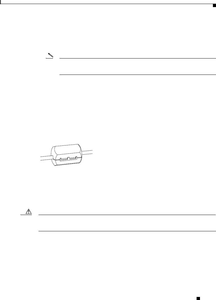
To attach the audio cable to the IP dome, you will need the white snap on ferrite core and audio Y cable that are included in the optional audio/video cables accessory kit, which you can purchase from Cisco (Cisco part number CIVS-IPCA-1017=). Attach the white snap on ferrite core to the audio Y cable (from the optional accessory kit) at approximately 10 inches (25 cm) away from where the cable connects to the IP dome. To do so, lift the tabs to open the ferrite core, pass the cable through the ferrite core (do not loop the cable), then snap the ferrite core shut to secure it on the cable. See Figure 2-1.
Figure 2-1 Passing the Audio Cable through a Ferrite Core
•If you will use external input devices or output device that trigger alarms (connect through alarm input ports) or respond to alarms (connect through alarm output ports), run cables from each device to the mounting location. You can use up to two input devices and up to two output devices.
•If the dome requires a waterproof installation, use waterproof tubing to protect the cables that you run to the dome.
•Have an analog monitor available on which to view video while adjusting the field of view.
Caution Use the analog monitor only to point the IP camera to the desired field of view; do not use it to manually adjust the focus or zoom. Doing so may damage the lens. Instead, use the Focus/Zoom window in the configuration software to remotely set the focus and zoom for the IP camera.
•Have the following tools available:
–Phillips-head screwdriver
–Small flat-head screwdriver
–Cutting tool to cut a hole in a ceiling tile (required for mounting in a ceiling tile)
–Drill bits (required for surface mounting on a solid surface)
Cisco Video Surveillance 2630 IP Dome User Guide
|
OL-24130-02 |
2-3 |
|
|
|
Chapter 2 Getting Started
Installing the Cisco Video Surveillance 2630 IP Dome
Mounting with a Conduit Base
You can mount the 2630 IP dome with an optional conduit base (CIVS-IPCA-1006=) in situations where you cannot cut a hole through a surface for cables or where cables run through a small hole in a surface.
To mount the IP camera with a conduit base, perform the following steps:
Note When you disassemble the IP dome for mounting as described in these steps, make sure to remove any protective packing material that is installed between components.
Procedure
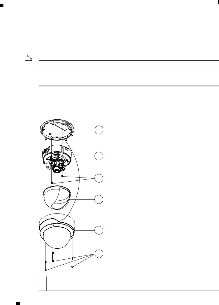
Step 1 Remove the dome assembly by unscrewing the three security TORX screws and pulling the dome away from the base plate (see Figure 2-2).
Use the TORX screwdriver that is provided with the IP dome to unscrew these screws.
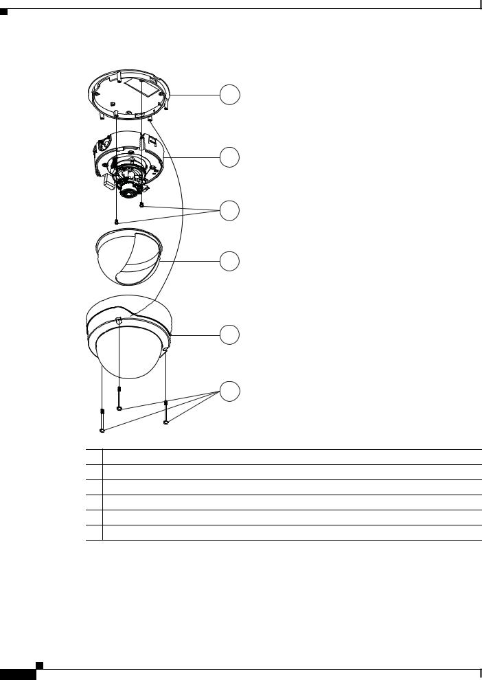
Figure 2-2 Disassembling the 2630 IP Dome Components
1
2
3
4
5
6
1Base plate
2Camera unit
Cisco Video Surveillance 2630 IP Dome User Guide
2-4 |
OL-24130-02 |
|
|
Chapter 2 Getting Started
Installing the Cisco Video Surveillance 2630 IP Dome
3Camera unit screws (2)
4Privacy shield
5Dome assembly
6TORX security screws (3)
Step 2 Remove the Privacy shield by squeezing it inward to release it from the four tabs that hold it into place (see Figure 2-2).
Step 3 Remove the camera unit from the base plate by using a Phillips-head screwdriver to unscrew the two camera unit screws and pressing the tabs that lock the camera unit to the base plate (see Figure 2-2).
Step 4 Use the template provided to mark the locations in the mounting surface for four screw holes, and for one cabling hole, if cables come through the surface.
Step 5 Drill 4 holes for screws.
The screw holes should be the appropriate size for the mounting hardware that you are using.
Step 6 Take one of these actions:
•If cables run through the surface, drill a hole for the cables.
•If cables run parallel to the surface, unscrew the cable entry plug from the desired entry hole in the side of the conduit base. Then screw the cable entry plug into the bottom cable entry hole.
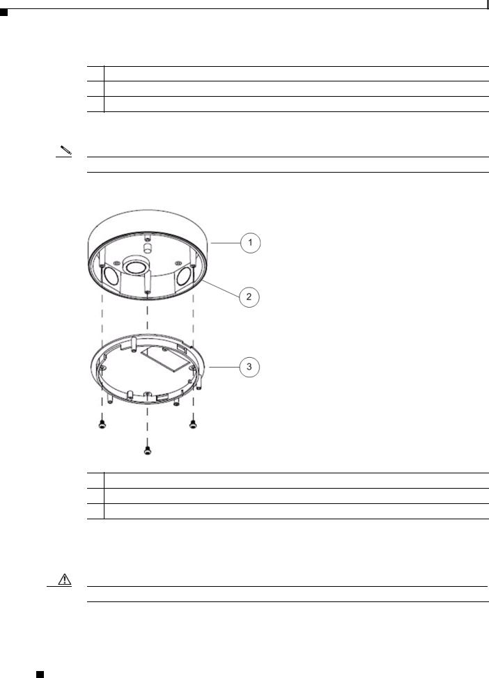
Step 7 Attach the conduit base to the surface by using four screws that are appropriate for the surface see (Figure 2-3).
To ensure a water-tight installation, insert the rubber sheet, provided, between the conduit base and the ceiling or wall.
Use anchors if necessary and make sure to attach the conduit base securely.
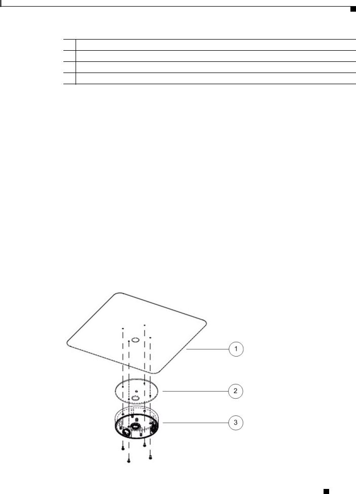
Figure 2-3 Attaching the Conduit Base to a Ceiling or Wall
Cisco Video Surveillance 2630 IP Dome User Guide
|
OL-24130-02 |
2-5 |
|
|
|
Chapter 2 Getting Started
Installing the Cisco Video Surveillance 2630 IP Dome
1Ceiling or wall
2Rubber sheet
3Conduit base
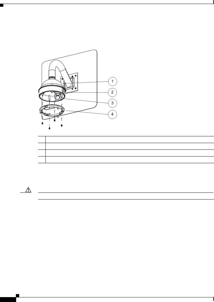
Step 8 Attach the base plate to the conduit base with the four screws, provided (see Figure 2-4).
Note Make sure the that gasket is clean and in place.
Figure 2-4 Attaching Base Plate to Conduit Base
1Conduit base
2Gasket
3Base plate
Step 9 Put the an category 5 or higher Ethernet cable through the appropriate cable entry hole in the conduit base and the opening in the base plate and connect the cable to the LAN port on the IP dome (see Figure 1-1 on page 1-3).
Caution Do not lift the IP dome by the Ethernet cable.
Step 10 Put the power cable through the appropriate cable entry hole in the conduit base and the opening in the base plate and connect it to the power input on the IP dome (see Figure 1-1 on page 1-3).
Cisco Video Surveillance 2630 IP Dome User Guide
2-6 |
OL-24130-02 |
|
|
Chapter 2 Getting Started
Installing the Cisco Video Surveillance 2630 IP Dome
To connect a power cable, use a flat-head screwdriver to depress the brown tabs on the power input and connect bare positive, negative, and ground wires as shown on the label that is affixed to the IP dome.
Step 11 (Optional) Connect an external speaker, microphone, or both to the Y cable, then connect the Y cable to the audio port on the IP dome.(see Figure 1-1 on page 1-3). The Y cable that is included in the optional audio/video cables accessory kit can be purchased from Cisco (Cisco part number CIVS-IPCA-1017=).
Each device connects to the audio cable through a standard 3.5 mm mini phone jack. A speaker connects to the green jack, which is labeled “Audio Out.” A microphone connects to the pink jack, which is labeled “Audio In.”
Step 12 (Optional) Use the GPIO ports to connect external devices that trigger alarms (connect through alarm input ports) or respond to alarms (connect through alarm output ports).
See Figure 1-1 on page 1-3.
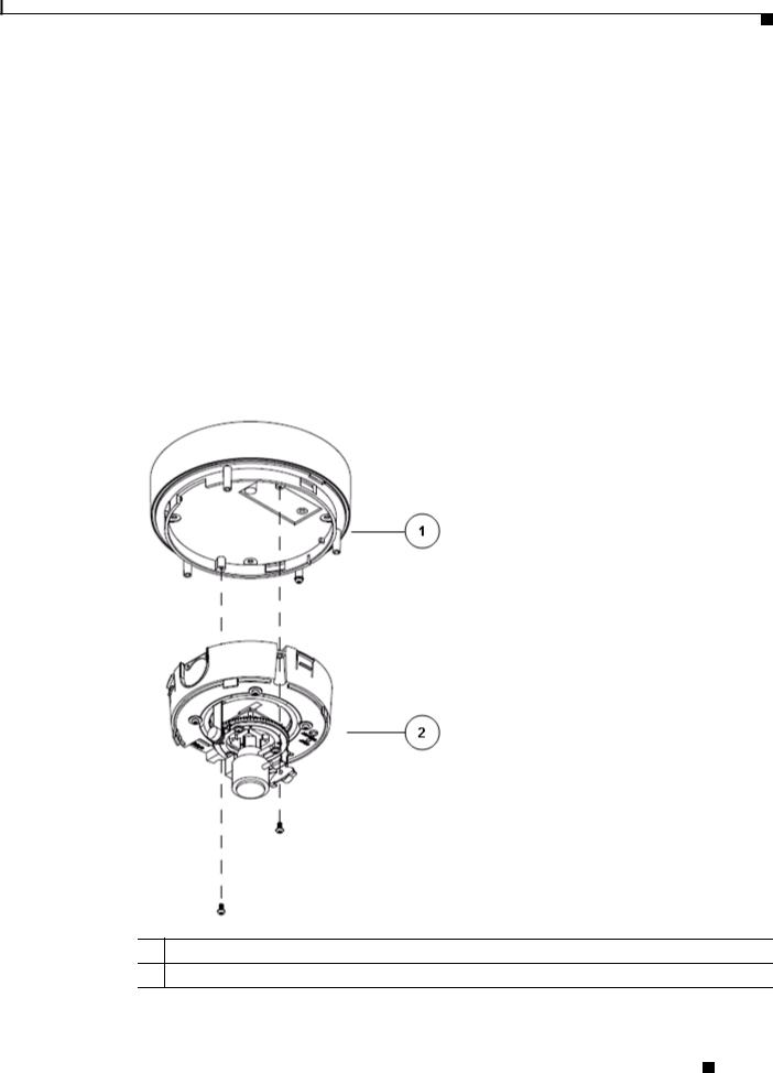
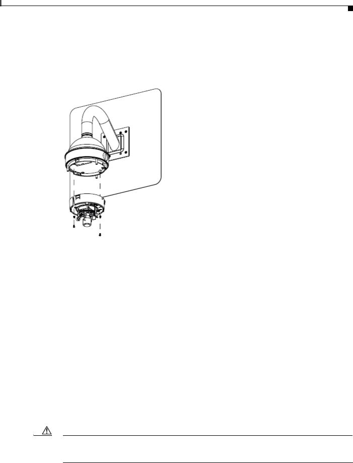
Step 13 Attach the camera unit to the base plate by aligning the three tabs on the camera unit with the slots on the base plate, pressing the camera unit into the base plate until the tabs snap into place, and securing the camera unit with the two camera unit screws (see Figure 2-5).
Figure 2-5 Attaching the Camera to the Base Plate
1Base plate
2Camera unit
Cisco Video Surveillance 2630 IP Dome User Guide
|
OL-24130-02 |
2-7 |
|
|
|

Chapter 2 Getting Started
Installing the Cisco Video Surveillance 2630 IP Dome
Step 14 See Figure 2-13 on page 2-18 and take these actions to adjust the camera lens to obtain the desired image:
•Temporarily attach an analog monitor to the IP dome so that you can see video while adjusting the camera. If the cable from the monitor terminates with a 3.5 mm jack, plug it into the analog video output port on the IP dome. If the cable terminates with a BNC connector, connect it to the mini cable with BNC adapter, then plug the cable into the analog video output port. The mini cable with BNC adapter is included in the audio/video cables accessory kit, which you can purchase from Cisco (Cisco part number CIVS-IPCA-1017=).
•Make the following adjustments, viewing the video on the analog monitor as needed:
–Back focus—The back focus is factory set for optimal use and should not require adjustments. In the event that it does need to be adjusted, use the 0.9 mm Allen wrench that is supplied with the IP camera to loosen the three back focus hex screws, then adjust the back focus by aiming the IP camera at an object that is at least 15 feet (4.5 meters) away and gently sliding the lens toward or away from the camera. Take care not to pull the lens completely away from the camera. Obtain a sharp picture in both wide-angle and telephoto positions. When the focus is set as desired, use the Allen wrench to tighten the three back focus hex screws.
–Pan—Use a Phillips-head to loosen the panning lock screw, then rotate the camera to obtain the desired image, then tighten the panning lock screw.
–Tilt—Loosen the two tilt lock screws, adjust the lens to obtain the desired image, then tighten the screws.
Caution Do not manually adjust the focus or zoom for the IP camera. Attempting to manually do so may damage the IP camera lens. Instead, use the Focus/Zoom window in the configuration software to remotely set the focus and zoom for the IP camera.
Step 15 Replace the privacy shield by squeezing it to fit inside the four tabs on the camera unit (see Figure 2-6).
Make sure to adjust the privacy shield inside the dome and trim ring assembly so that it does not block the lens from capturing video.
Cisco Video Surveillance 2630 IP Dome User Guide
2-8 |
OL-24130-02 |
|
|
Chapter 2 Getting Started
Installing the Cisco Video Surveillance 2630 IP Dome
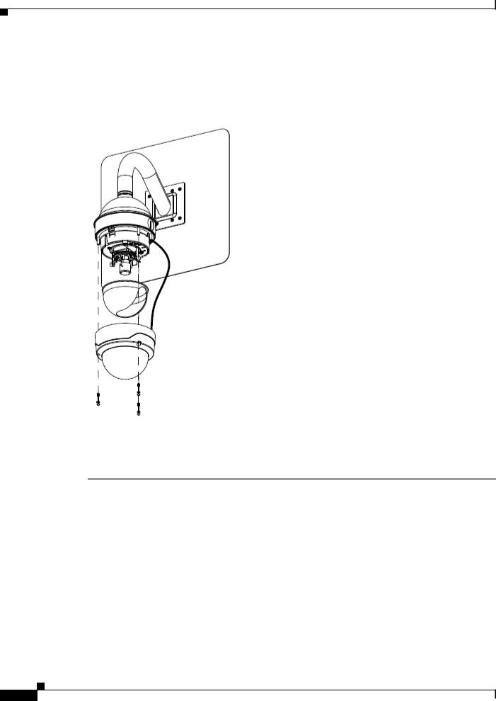
Figure 2-6 Attaching the Privacy Shield and Dome
Step 16 Attach the dome assembly by aligning its tab with the opening in the base plate, pressing it into place, and securing the three TORX screws (see Figure 2-6).
Make sure that the security strap that connects the dome assembly to the camera housing is in place.
Mounting with a Pendant
You can mount the 2630 IP dome to a wall or ceiling with an optional pendant.
Procedure
Step 1 Remove the dome assembly by unscrewing the three security TORX screws and pulling the dome away from the base plate (see Figure 2-7).
Use the TORX screwdriver that is provided with the IP dome to unscrew these screws.
Cisco Video Surveillance 2630 IP Dome User Guide
|
OL-24130-02 |
2-9 |
|
|
|
Chapter 2 Getting Started
Installing the Cisco Video Surveillance 2630 IP Dome
Figure 2-7 Disassembling the 2630 IP Dome Components
1
2
3
4
5
6
1Base plate
2Camera unit
3Camera unit screws (2)
4Privacy shield
5Dome assembly
6TORX security screws (3)
Step 2 Attach the pendant to a ceiling or wall with 4 screws, as shown in Figure 2-8.
You can mount the pendant using the inside mounting holes or the outside mounting holes. Use four screws that are appropriate for the surface on which you are mounting, and use anchors, if needed.
|
Cisco Video Surveillance 2630 IP Dome User Guide |
2-10 |
OL-24130-02 |
Chapter 2 Getting Started
Installing the Cisco Video Surveillance 2630 IP Dome
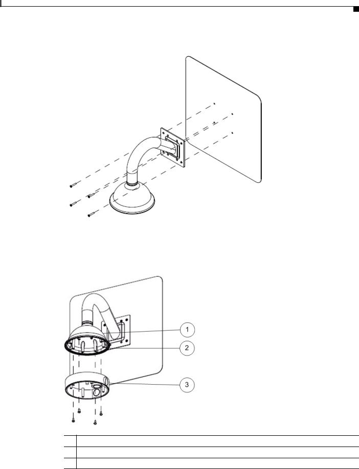
Figure 2-8 Attaching the Pendant to a Ceiling or Wall
Step 3 Attach the conduit base to the pendant with 4 screws, as shown in Figure 2-9.
Make sure the gasket on the pendant is in place and clean.
Figure 2-9 Attaching the Conduit Base to the Pendant
1Pendant
2Gasket
3Conduit base
|
|
Cisco Video Surveillance 2630 IP Dome User Guide |
|
|
|
|
|
|
|||
|
OL-24130-02 |
|
|
2-11 |
|
|
|
|
|
||
Chapter 2 Getting Started
Installing the Cisco Video Surveillance 2630 IP Dome
Step 4 Attach the base plate to conduit with 4 screws, provided, as shown in Figure 2-10.
Make sure that the gasket is clean and in place.
Figure 2-10 Attaching the Base Plate to the Conduit
1Pendant
2Conduit base
3Gasket
3 Base plate
Step 5 Put the an category 5 or higher Ethernet cable through the appropriate cable entry hole in the conduit base and the opening in the base plate and connect the cable to the LAN port on the IP dome (see Figure 1-1 on page 1-3).
Caution Do not lift the IP dome by the Ethernet cable.
Step 6 Put the power cable through the appropriate cable entry hole in the conduit base and the opening in the base plate and connect it to the power input on the IP dome (see Figure 1-1 on page 1-3).
To connect a power cable, use a flat-head screwdriver to depress the brown tabs on the power input and connect bare positive, negative, and ground wires as shown on the label that is affixed to the IP dome.
Step 7 (Optional) Connect an external speaker, microphone, or both to the Y cable, then connect the Y cable to the audio port on the IP dome.(see Figure 1-1 on page 1-3). The Y cable that is included in the optional audio/video cables accessory kit can be purchased from Cisco (Cisco part number CIVS-IPCA-1017=).
Each device connects to the audio cable through a standard 3.5 mm mini phone jack. A speaker connects to the green jack, which is labeled “Audio Out.” A microphone connects to the pink jack, which is labeled “Audio In.”
Step 8 (Optional) Use the GPIO ports to connect external devices that trigger alarms (connect through alarm input ports) or respond to alarms (connect through alarm output ports).
See Figure 1-1 on page 1-3.
|
Cisco Video Surveillance 2630 IP Dome User Guide |
2-12 |
OL-24130-02 |
Chapter 2 Getting Started
Installing the Cisco Video Surveillance 2630 IP Dome
Step 9 Attach the camera unit to the base plate by aligning the three tabs on the camera unit with the slots on the base plate, pressing the camera unit into the base plate until the tabs snap into place, and securing the camera unit with the two camera unit screws (see Figure 2-11).
Figure 2-11 Attaching the Camera to the Base Plate
Step 10 See Figure 2-13 on page 2-18 and these actions to adjust the camera lens to obtain the desired image
•Temporarily attach an analog monitor to the IP dome so that you can see video while adjusting the camera. If the cable from the monitor terminates with a 3.5 mm jack, plug it into the analog video output port on the IP dome. If the cable terminates with a BNC connector, connect it to the mini cable with BNC adapter, then plug the cable into the analog video output port. The mini cable with BNC adapter is included in the audio/video cables accessory kit, which you can purchase from Cisco (Cisco part number CIVS-IPCA-1017=).
•Make the following adjustments, viewing the video on the analog monitor as needed:
–Back focus—The back focus is factory set for optimal use and should not require adjustments. In the event that it does need to be adjusted, use the 0.9 mm Allen wrench that is supplied with the IP camera to loosen the three back focus hex screws, then adjust the back focus by aiming the IP camera at an object that is at least 15 feet (4.5 meters) away and gently sliding the lens toward or away from the camera. Take care not to pull the lens completely away from the camera. Obtain a sharp picture in both wide-angle and telephoto positions. When the focus is set as desired, use the Allen wrench to tighten the three back focus hex screws.
–Pan—Use a Phillips-head to loosen the panning lock screw, then rotate the camera to obtain the desired image, then tighten the panning lock screw.
–Tilt—Loosen the two tilt lock screws, adjust the lens to obtain the desired image, then tighten the screws.
Caution Do not manually adjust the focus or zoom for the IP camera. Attempting to manually do so may damage the IP camera lens. Instead, use the Focus/Zoom window in the configuration software to remotely set the focus and zoom for the IP camera.
|
|
Cisco Video Surveillance 2630 IP Dome User Guide |
|
|
|
|
|
|
|||
|
OL-24130-02 |
|
|
2-13 |
|
|
|
|
|
||
Chapter 2 Getting Started
Performing the Initial Setup of the IP Camera
Step 11 Replace the privacy shield by squeezing it to fit inside the four tabs on the camera unit (see Figure 2-12).
Make sure to adjust the privacy shield inside the dome and trim ring assembly so that it does not block the lens from capturing video.
Figure 2-12 Attaching the Privacy Shield and Dome
Step 12 Attach the dome assembly by aligning its tab with the opening in the base plate, pressing it into place, and securing the three TORX screws (see Figure 2-12).
Make sure that the security strap that connects the dome assembly to the camera housing is in place.
Performing the Initial Setup of the IP Camera
After you install IP camera, or after you perform a factory reset procedure, you must access the IP camera and make initial configuration settings. These settings include administrator and root passwords, and whether the IP camera can be accessed through an HTTP connection in addition to the default HTTPS (HTTP secure) connection.
To make these configuration settings, you connect to the IP camera from any PC that is on the same network as the IP camera. The PC must meet these requirements:
•Operating system—Microsoft Windows 2000, XP, or Vista
•Browser—Internet Explorer 6.x with Service Pack 2, or later
|
Cisco Video Surveillance 2630 IP Dome User Guide |
2-14 |
OL-24130-02 |

Chapter 2 Getting Started
Performing the Initial Setup of the IP Camera
In addition, you must know the IP address of the IP camera. By default, when the IP camera powers on, it attempts to obtain an IP address from a DHCP server in your network. If the camera cannot obtain an IP address through DCHP within 90 seconds, it uses a default IP address of 192.168.0.100.
To connect to the IP camera for the first time and make initial configuration settings, perform the following steps. You can change these configuration settings in the future as described in the “Initialization Window” section on page 3-25.
Procedure
Step 1 Start Internet Explorer, enter HTTPS://ip_address in the address field, and press Enter.
Replace ip_address with the IP address that the IP camera obtained through DHCP or, if the camera is unable to obtain this IP address, enter 192.168.0.100.
The Account window appears.
Step 2 In the Set Password and Verify Password fields in the Admin column, enter a password for the IP camera administrator.
You must enter the same password in both fields. The password is case sensitive and must contain at least eight characters, which can be letters, numbers, and special characters, but no spaces. Special characters are: ! " # $ % & ' ( ) * + , - . : ; < = > ? @ [ \ ] ^ _ ` { | } ~.
Step 3 In the Set Password and Verify Password fields in the Root column, enter a password that is used when accessing the IP camera through a Secure Shell (SSH) connection.
You must enter the same password in both fields. The password is case sensitive and must contain at least eight characters, which can be letters, numbers, and special characters, but no spaces. Special characters are: ! " # $ % & ' ( ) * + , - . : ; < = > ? @ [ \ ] ^ _ ` { | } ~.
You use the root password if you need to troubleshoot the IP camera through a SSH connection with the assistance of the Cisco Technical Assistance Center.
Step 4 In the HTTP area, click the HTTP radio button if you want to allow both HTTP and HTTPS connections to the IP camera.
The default setting is HTTPS, which allows only HTTPS (secure) connections to the IP camera.
Step 5 Click Apply.
The IP camera reboots.
Step 6 After the IP camera reboots, start Internet Explorer and, in the Address field, enter the following:
protocol://ip_address
where:
•protocol is HTTPS or HTTP. (You can use HTTP only if you enabled it in Step 4.)
•ip_address is the IP address that you used in Step 1.
Step 7 If you are prompted to install ActiveX controls, which are required to view video from the IP camera, follow the on-screen prompts to do so.
The Main window appears and video from the IP camera starts playing automatically.
You can take these actions in the Main window:
•Click the Setup link to access configuration menus for the camera. For detailed information about these menus, see Chapter 3, “Configuring and Managing the IP Camera.”
•Click the Home link to view and control live video from the camera. For detailed information about these actions, see Chapter 4, “Viewing Live Video.”
•Click the Logout button to exit the window.
|
|
Cisco Video Surveillance 2630 IP Dome User Guide |
|
|
|
|
|
|
|||
|
OL-24130-02 |
|
|
2-15 |
|
|
|
|
|
||

Chapter 2 Getting Started
Accessing the IP Camera Windows
Accessing the IP Camera Windows
After you perform the initial configuration as described in the “Performing the Initial Setup of the IP Camera” section on page 2-14, follow the steps in this section each time that you want to access the IP camera windows to make configuration settings or view live video.
You access these windows by connecting to the IP camera from any PC that is on the same network as the IP camera and that meets these requirements:
• Operating system—Microsoft Windows 2000, Windows XP, or Vista
•Browser—Internet Explorer 6.x with Service Pack 2, or later You need this information to access the IP camera windows:
•IP address of the IP camera. By default, the IP camera attempts to obtain an IP address from a DHCP server in your network. If the IP camera cannot obtain an IP address through DHCP within 90 seconds of powering up or resetting, it uses the default IP address of 192.168.0.100.
•Port number, if other than the default value. Default port numbers for the IP camera are 443 for HTTPS and 80 for HTTP. The IP camera administrator can enable an alternative HTTPS port and an alternative HTTP port as described in the “Advanced Setup Window” section on page 3-7.
•Your user name and password for the IP camera. The IP camera administrator configures user names and passwords as described in the “Users Window” section on page 3-12.
To access the IP camera windows, follow these steps:
Procedure
Step 1 Start Internet Explorer and enter the following in the address field:
protocol://ip_address:port_number
where:
•protocol is HTTPS for a secure connection or HTTP for a non-secure connection. You can use HTTP only if you configure the camera to accept non-secure HTTP connections as described in the “Performing the Initial Setup of the IP Camera” section on page 2-14.
•ip_address is the IP address of the IP camera. The default IP address is 192.168.0.100.
•port_number is the port number that is used for HTTPS or HTTP connections to the IP camera. You do not need to enter a port number if you are connecting through the default HTTPS port 443 or the default HTTP port 80.
For example,
•Enter the following for a secure connection if the IP address is 192.168.0.100 and the HTTPS port number is 443:
https://192.168.0.100
•Enter the following for a secure connection if the IP address is 203.70.212.52 and the HTTPS port number is 1024:
https://203.70.212.52:1024
•Enter the following for a non-secure connection if the IP address is 203.70.212.52 and the HTTP port number is 80:
http://203.70.212.52
|
Cisco Video Surveillance 2630 IP Dome User Guide |
2-16 |
OL-24130-02 |

Chapter 2 Getting Started
Adjusting the Video Image
•Enter the following for a non-secure connection if the IP address is 203.70.212.52 and the HTTP port number is 1024:
http://203.70.212.52:1024
Step 2 Enter your IP camera user name and password when prompted, then click OK.
To log in as the IP camera administrator, enter the user name admin (all lower case) and the password that is configured for the administrator. To log in as a user, enter the user name and password that are configured for the user.
The Main window appears and video from the IP camera starts playing automatically. You can take these actions in the Main window:
•Click the Setup link to access configuration menus for the camera. For detailed information about these menus, see Chapter 3, “Configuring and Managing the IP Camera.”
•Click the Home link to view and control live video from the camera. For detailed information about these actions, see Chapter 4, “Viewing Live Video.”
•Click the Logout button to exit the window.
Adjusting the Video Image
As part of the IP camera installation process, you make pan and tilt settings (and back focus settings if necessary) for the camera in the dome. If you ever need to change these settings, follow these steps:
Procedure
Step 1 Unscrew the three security TORX screws using the TORX screwdriver that supplied with the IP dome and pull the dome assembly away from the base plate
Step 2 Remove the Privacy shield by squeezing it inward to release it from the four tabs that hold it into place.
Step 3 See Figure 2-13 and take these actions to adjust the camera lens to obtain the desired image
•Temporarily attach an analog monitor to the IP dome so that you can see video while adjusting the camera. If the cable from the monitor terminates with a 3.5 mm jack, plug it into the analog video output port on the IP dome. If the cable terminates with a BNC connector, connect it to the mini cable with BNC adapter, then plug the cable into the analog video output port. The mini cable with BNC adapter is included in the audio/video cables accessory kit, which you can purchase from Cisco (Cisco part number CIVS-IPCA-1017=).
•Make the following adjustments, viewing the video on the analog monitor as needed:
–Rotation—The rotation is factory set and should not require adjustments. In the event that it does need to be adjusted, turn the notched rotation wheel until you achieve the desired image.
–Pan—Use a Phillips-head to loosen the panning lock screw (the one slightly recessed in a cutout), then rotate the camera to obtain the desired image, then tighten the panning lock screw.
–Tilt—Loosen the two tilt lock screws, adjust the lens to obtain the desired image, then tighten the screws.
–Back focus—The back focus is factory set for optimal use and should not require adjustments. In the event that it does need to be adjusted, use the 0.9 mm Allen wrench that is supplied with the IP camera to loosen the back focus hex screw, then adjust the back focus by aiming the IP camera at an object that is at least 15 feet (4.5 meters) away and gently sliding the lens toward
|
|
Cisco Video Surveillance 2630 IP Dome User Guide |
|
|
|
|
|
|
|||
|
OL-24130-02 |
|
|
2-17 |
|
|
|
|
|
||
Chapter 2 Getting Started
Adjusting the Video Image
or away from the camera. Take care not to pull the lens completely away from the camera.Obtain a sharp picture in both wide-angle and telephoto positions. When the focus is set as desired, use the Allen wrench to tighten the back focus hex screw.
Caution Do not manually adjust the focus or zoom for the IP camera. Attempting to manually do so may damage the IP camera lens. Instead, use the Focus/Zoom window in the configuration software to remotely set the focus and zoom for the IP camera.
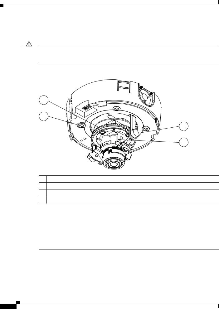
Figure 2-13 Adjusting the Camera Lens on the 2630 IP Dome
1
2
3
4
1Rotation wheel
2Panning lock screw
3Tilt lock screws (2)
4Back focus hex screws (3)
Step 4 Remove the analog monitor cable from the analog video output port.
Step 5 Replace the privacy shield by squeezing it to fit inside the four tabs on the camera unit.
Make sure to adjust the privacy shield inside the dome and trim ring assembly so that it does not block the lens from capturing video.
Step 6 Align the tab on the dome assembly with the opening in the base plate, press the dome assembly into place, and securing the three TORX screws
|
Cisco Video Surveillance 2630 IP Dome User Guide |
2-18 |
OL-24130-02 |
Loading...