


 Loading...
QUICK START GUIDE
Cisco ASR 1006 Router
1Documentation and Resources
2Prepare for Installation
3Rack-Mount the Router
4Connect the Router to the Network
5Start the System
6Configure the Router
7After Installation
1 Documentation and Resources
Documentation for the Cisco ASR 1000 Series Aggregation Services Routers documentation is online with the exception of the regulatory compliance and safety documentation and the Cisco ASR 1000 Series Aggregation Services Routers documentation flyer. Refer to the following documentation for installation and replacement of parts (including shared port adapters) and regulatory compliance information.
•Shared port adapter documentation—See the Cisco ASR 1000 Series Aggregation Services Routers SIP and SPA Hardware Installation Guide
•Hardware installation documentation—See the Cisco ASR 1000 Series Aggregation Services Routers Hardware Installation and Initial Configuration Guide
Document Revision History
The Document Revision History table below records technical changes to this document.
Document Version |
Date |
Change Summary |
|
|
|
OL-13209-03 |
November 2008 |
Improved the two-minute window allotted time to replace a power |
|
|
supply. You now have up to a maximum of five minutes to replace a |
|
|
power supply. |
|
|
|
OL-13209-02 |
October 2008 |
Support for Cisco ASR1000-ESP20 |
|
|
|
OL-13209-01 |
May 2008 |
First version of this document. |
|
|
|
Documentation Survey
Is Cisco documentation helpful? Click here or go to http://www.cisco.com/warp/public/732/docsurvey/rtg/ to give us your feedback.
Obtaining Documentation and Submitting a Service Request
For information on obtaining documentation, submitting a service request, and gathering additional information, see the monthly What’s New in Cisco Product Documentation, which also lists all new and revised Cisco technical documentation, at:
http://www.cisco.com/en/US/docs/general/whatsnew/whatsnew.html
Subscribe to the What’s New in Cisco Product Documentation as a Really Simple Syndication (RSS) feed and set content to be delivered directly to your desktop using a reader application. The RSS feeds are a free service and Cisco currently supports RSS version 2.0.
2

2 Prepare for Installation
This section contains information about tools and parts, warnings, site preparation information, and information for rack-mount installation and equipment shelf or tabletop installation.
Warning |
Only trained and qualified personnel should install, replace, or service this equipment. Statement 1030 |
Before beginning this router installation, read the Regulatory Compliance and Safety Information for the Cisco ASR 1000 Series Aggregation Services Routers document.
Site Preparation and Unpacking
•Lift the router safely out of the packing container.
•Ensure the power service at the site is suitable for the router you are installing.
•Check the packing slip to ensure that all the proper components are present.
•Locate and have accessible the Site Log for recording information about this installation.
Tools and Parts
Use the following list of tools and parts as a checklist for preparing to install the Cisco ASR 1000 Series Aggregation Services Router:
•ESD-preventative wrist strap
•AC power cord
•Appropriate cables to connect the router to the network and to the console terminal
•Optional tape measure and level
•Screwdrivers: Number 2 Phillips screwdriver and 3/16-inch flat-blade screwdriver
•Grounding lug and wires
•The rack-mount and cable-management kit:
–Four 19-inch rack-mount brackets (front and rear rails) and two cable-management brackets
–Three sets of screws: one set for front rack-mount brackets (black screws), another set for rear rack-mount brackets, and a set for the cable-management brackets (package with four screws)
Prepare for Equipment Shelf or Tabletop Installation
For a equipment shelf or tabletop installation, verify the following before installing the router:
•The router is off the floor and has adequate ventilation.
•An adequate chassis ground (earth) connection exists for the router.
•The router needs at last 3 inches (7.62 cm) of clearance at the inlet and exhaust vents (sides of router).
•The router needs 19 inches (48.26 cm) of clearance at the front and rear to allow for field-replaceable unit replacement or installation, or to access cables or equipment.
•The shared port adapters are installed. If shared port adapters are not installed, then the slots must not be empty. Use filler panels for an empty slot.
3
Prepare for Rack-Mount Installation
Before you begin the rack-mounting tasks:
•Decide whether or not you want to front rack-mount or rear rack-mount the chassis
•Decide whether or not you want to attach cable-management brackets to your chassis.
Note If you install cable-management brackets, make certain that the chassis is installed in the equipment rack first.
•Decide if a two-post or four-post rack-mount will be used.
3 Rack-Mount the Router
This section provides information for rack-mounting the router.
Attach the Rack-Mount Brackets—Chassis Front-Mounted
To install the rack-mount brackets on a Cisco ASR 1006 Router for a front rack-mount configuration, follow these steps:
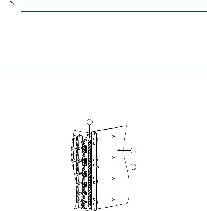
Step 1 Locate the threaded holes in the front sides of the chassis. Make certain that you hold the front rack-mount bracket with the ear and holes facing outward and towards the front of the chassis.
Step 2 Align the rack-mount bracket to the side of the router. Depending on which set of rack-mount bracket holes you choose to use to attach the rack-mount bracket to the router, the chassis will either be recessed in the rack or protrude from the rack.
Step 3 Position the front rack-mount bracket top hole with the chassis first top hole behind the side vent holes as shown in Figure 1Figure 1.
Figure 1 Cisco ASR 1006 Router Vent Hole Location and Front Rack-Mount Brackets
1
CiscoASR 1006

 2
2


 1
1

 0
0


 F1
F1


 F0
F0


 R1
R1

 R0
R0
2
3
280093
1 |
Chassis vent hole location |
3 |
Front rack-mount bracket ear holes |
|
|
|
|
2 |
Front rack-mount bracket |
|
|
|
|
|
|
4

Step 4 Insert and tighten the black screws on one side.
Figure 2 Front Rack-Mount Brackets for the Cisco ASR 1006 Router
|
C/A |
|
A/L |
2 |
0 |
1 |
|
|
C/A |
|
A/L |
|
0 |
|
1 |
|
C/A |
|
A/L |
1 |
0 |
1 |
|
|
C/A |
|
A/L |
|
0 |
|
1 |
|
C/A |
|
A/L |
0 |
0 |
1 |
|
|
C/A |
 A/L
A/L 
0
|
|
1 |
|
F1 |
PWR |
ACTV |
|
STAT |
|||
STBY |
|||
|
ASR1000-ESP10 |
||
F0 |
PWR |
ACTV |
STAT |
STBY |
|
|
ASR1000-ESP10 |
|
|
PWR |
|
CRIT |
|
|
|
ACTV |
MAJ |
|
||
R1 |
STAT |
CO |
|||
STBY |
MIN |
||||
|
A |
||||
|
ASR1000-RP1 |
|
|
||
|
|
|
|
0 |
|
|
PWR |
|
CRIT |
|
|
|
ACTV |
MAJ |
|
||
R0 |
STAT |
CO |
|||
STBY |
MIN |
||||
|
A |
||||
|
ASR1000-RP1 |
|
|
||
|
|
|
|
0 |
|
C/A |
|
A/L |
C/A |
|
A/L |
|
2 |
C/A |
3 |
A/L |
C/A |
|
A/L |
|
2 |
|
3 |
C/A |
|
A/L |
C/A |
|
A/L |
|
2 |
C/A |
3 |
|
|
A/L |
C/A |
|
A/L |
|
2 |
|
3 |
C/A |
|
A/L |
C/A |
|
A/L |
|
2 |
C/A |
3 |
|
|
A/L |
C/A |
|
A/L |
|
2 |
|
3 |
C/A |
|
US |
ASR1000-SIP10 |
A |
|
||
/L |
|
|
|
|
ST AT |
|
|
|
SPA-4XOC3-POS |
|
|
C/A |
|
|
|
A/L |
|
US |
0 |
ST AT |
|
||
|
|
|
|
|
SPA-4XOC3-POS |
|
|
|
|
|
PWR STATUS |
|
|
|
0 |
C/A |
|
US |
ASR1000-SIP10 |
A |
|
||
/L |
|
|
|
|
STAT |
|
|
|
SPA-4XOC3-POS |
|
|
C/A |
|
|
|
A/L |
|
US |
0 |
|
STAT |
|
|
|
|
|
|
|
SPA-4XOC3-POS |
|
|
|
|
|
PWR STATUS |
|
|
|
0 |
C/A |
|
US |
ASR1000-SIP10 |
A/L |
|
||
|
STAT |
|
|
|
SPA-4XOC3-POS |
|
|
C/A |
|
|
A/L |
|
0 |
|
STA |
TUS |
|
SPA-4XOC3-POS |
|
|
|
PWR STATUS |
|
|
0 |
C/A |
|
|
A/L |
C/A |
|
|
A/L |
C/A |
|
1 |
A/L |
C/A |
|
2 |
|
3 |
|
A/L |
C/A |
|
|
A/L |
C/A |
|
1 |
A/L |
|
|
2 |
|
|
3 |
C/A |
|
|
A/L |
C/A |
|
|
A/L |
C/A |
|
1 |
A/L |
C/A |
|
2 |
|
3 |
|
A/L |
C/A |
|
|
A/L |
C/A |
|
1 |
A/L |
|
|
2 |
|
|
3 |
C/A |
|
|
A/L |
C/A |
|
|
A/L |
C/A |
|
1 |
A/L |
|
|
|
C/A |
|
2 |
|
3 |
|
A/L |
C/A |
|
|
A/L |
C/A |
|
1 |
A/L |
|
|
2 |
|
|
3 |
|
|
|
Cisco |
ASR |
1006 |
|
|
|
|
|
|
C/A |
|
|
|
|
|
A/L |
|
TUS |
|
|
|
|
STA |
|
|
|
|
|
|
|
|
|
|
|
SPA-4XOC3-POS |
|
|
|
|
C/A |
|
|
|
|
|
A/L |
|
US |
|
|
|
|
STAT |
|
|
|
|
|
|
|
|
|
|
|
SPA-4XOC3-POS |
|
|
|
2 |
|
|
|
|
|
|
C/A |
|
|
|
|
|
A/L |
|
US |
|
|
|
|
STAT |
|
|
|
|
|
SPA-4XOC3-POS |
|
|
|
|
C/A |
|
|
|
|
|
/L |
|
|
|
|
|
A |
STAT |
US |
|
|
|
|
|
|
|
|
|
|
SPA-4XOC3-POS |
|
|
|
1 |
|
|
|
|
|
|
C/A |
|
|
|
|
|
A/L |
|
US |
|
|
|
|
STAT |
|
|
|
|
|
SPA-4XOC3-POS |
|
|
|
|
C/A |
|
|
|
|
|
A/L |
|
US |
|
|
|
|
STAT |
|
|
|
|
|
SPA-4XOC3-POS |
|
|
|
0 |
|
|
|
|
|
1
1
 HD
HD  USB
USB
 BF DISK
 HD
HD  USB
USB
 BF DISK


 CARRIER


 BITS
BITS


 CARRIER


 BITS
BITS
LINK  MGMTETHERNET
LINK 
 MGMTETHERNET
 CON
CON  AUX
AUX
 CON
CON  AUX
AUX


 F1
F1


 F0
F0


 R1
R1


 R0
R0
4 |
3 |
2 |
1 |
280035
1 |
Front rack-mount bracket screws |
3 |
Front rack-mount bracket ear holes |
|
|
|
|
2 |
Front rack-mount bracket |
4 |
Side vent location |
|
|
|
|
Step 5 Repeat Step 1 through Step 4 on the other side of the chassis. Use black screws to secure the rack-mount brackets to the chassis.
Step 6 To install the Cisco ASR 1006 Router in the equipment rack, see “Four-Post Rack Installation” section on page 6 or “Two-Post Rack Installation” section on page 8.
Attach the Rack-Mount Brackets—Chassis Rear Rack-Mounted
To install the rack-mount on a Cisco ASR 1006 Router for a rear rack-mount configuration, follow these steps:
Step 1 Locate the threaded holes in the rear sides of the chassis.
Step 2 Position the rear rack-mount bracket top hole with the chassis second top hole in from the back (See Figure 2). Make certain that you hold the rear rack-mount bracket with the earholes facing outward and towards the rear of the chassis. Align the rack-mount bracket to the side of the router.Attaching the Rear Rack-Mount Brackets to the Cisco ASR 1006 Router.
5
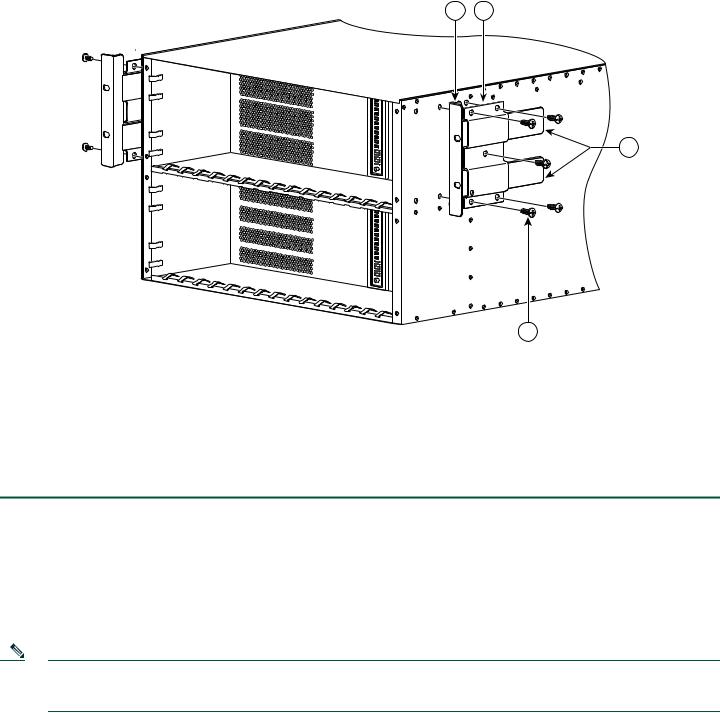
Figure 3 Cisco ASR 1006 Router Rear Rack-Mounting
1 2
1
1
0
0
3
280038
|
|
|
4 |
|
|
|
|
1 |
Rear rack-mount bracket attached to the chassis |
3 |
Components that slide into the mounted bracket |
|
|
|
|
2 |
Rear rack-mount bracket component |
4 |
Rear rack-mount bracket screw |
|
|
|
|
Step 3 Insert and tighten the five screws. After the bracket is secured to the side of the chassis, slide the two remaining components (item 3, Figure 3) into the side rack-mount bracket.
Step 4 Repeat Step 1 through Step 3 on the other side of the chassis. Use five screws on each side to secure the rear rack-mount brackets to the chassis.
This completes the procedure for attaching rear rack-mount brackets to the chassis. Continue on to Four-Post Rack Installation, page 6 or Two-Post Rack Installation, page 8.
Four-Post Rack Installation
This section describes the types of racks used for rack-mounting the chassis.
Note Inner clearance (the width between the inner sides of the two posts or rails) must be at least 19 inches (48.26 cm). The Cisco ASR1006 chassis requires a minimum of 7 rack units (22.3 inches or 56.6 cm) of vertical rack space. Airflow through the chassis is from front to back.
6
Figure 4 Installing the Cisco ASR 1006 Router in a Four-Post Rack
2 |
|
|
0 |
|
|
|
|
|
|
|
|
1 |
|
2 |
|
ASR1000-SIP10 |
|
|
|
|
|
|
|
|
3 |
SPA-4XOC3-POS |
|
|
|
|
|
|
|
|
|
|
|
|
0 |
|
|
|
|
|
|
|
|
|
1 |
|
|
|
0 |
|
|
|
|
|
|
2 |
|
|
|
|
|
|
|
|
|
3 |
SPA-4XOC3-POS |
|
|
|
|
|
|
|
|
|
|
|
|
|
|
|
|
|
PWR STATUS |
1 |
|
|
0 |
|
|
|
|
0 |
|
|
|
1 |
|
2 |
|
ASR1000-SIP10 |
|
|
|
|
|
|
|
|
3 |
SPA-4XOC3-POS |
|
|
|
|
|
|
|
|
|
|
|
|
0 |
|
|
|
|
|
|
|
|
|
1 |
|
|
|
0 |
|
|
|
|
|
|
2 |
|
|
|
|
|
|
|
|
|
3 |
SPA-4XOC3-POS |
|
|
|
|
|
|
|
|
|
|
|
|
|
|
|
|
|
PWR STATUS |
0 |
|
|
0 |
|
|
|
|
0 |
|
|
|
1 |
|
2 |
|
ASR1000-SIP10 |
|
|
|
|
|
|
|
|
3 |
SPA-4XOC3-POS |
|
|
|
|
|
|
|
|
|
|
|
|
0 |
|
|
|
|
|
|
|
|
|
1 |
|
|
|
0 |
|
|
|
|
|
|
2 |
|
|
|
|
|
|
|
|
|
3 |
SPA-4XOC3-POS |
|
|
|
|
|
|
|
|
|
F1 |
PWR |
ACTV |
|
|
|
|
|
PWR STATUS |
STAT |
|
|
|
|
|
|||
STBY |
|
|
|
|
|
0 |
||
|
ASR1000-ESP10 |
|
|
|
|
|
|
|
F0 |
PWR |
ACTV |
|
|
|
|
|
|
STAT |
STBY |
|
|
|
|
|
|
|
|
ASR1000-ESP10 |
|
|
|
|
|
|
|
|
PWR |
|
CRIT |
|
|
|
|
|
|
ACTV |
MAJ |
|
|
|
|
|
|
R1 |
STAT |
STBY |
MIN |
ACO |
|
HD |
|
|
|
ASR1000-RP1 |
|
|
|
USB |
|
|
|
|
|
|
|
0 |
1 |
BF |
|
|
|
|
|
|
|
DISK |
|
|
|
|
PWR |
|
CRIT |
|
|
|
|
CARRIER |
R0 |
STAT |
ACTV |
MAJ |
O |
|
HD |
|
LINK |
|
STBY |
MIN |
AC |
|
|
|
BITS |
|
|
ASR1000-RP1 |
|
|
|
USB |
|
MGMTETHERNET |
|
|
|
|
|
0 |
|
BF |
|
CON |
|
|
|
|
|
1 |
DISK |
|
|
|
|
|
|
|
|
|
|
CARRIER |
|
|
|
|
|
|
|
|
LINK |
|
|
|
|
|
|
|
|
BITS |
|
|
|
|
|
|
|
|
MGMTETHERNET |
|
|
|
|
|
|
|
|
CON |
|
|
Cisco |
|
|
ASR 1006 |
1 |
|
|
2 |
|
|
3 |
SPA-4XOC3-POS |
|
|
|
|
1 |
|
|
2 |
|
|
3 |
SPA- |
2 |
|
4XOC3-POS |
|
1 |
|
|
2 |
|
|
3 |
SPA-4XOC3-POS |
|
|
|
|
1 |
|
|
2 |
|
|
3 |
SPA- |
1 |
|
4XOC3-POS |
|
1 |
|
|
2 |
|
|
3 |
SPA-4XOC3-POS |
|
|
|
|
1 |
|
|
2 |
|
|
3 |
SPA- |
0 |
|
4XOC3-POS |


 F1
F1


 F0
F0
AUX


 R1
R1
AUX

 R0
R0
4 |
3 |
1
2
280084
1 |
Rear of four-post rack |
3 |
Ear holes for the chassis front rack-mount bracket |
|
|
|
|
2 |
Ear holes for the chassis rear rack-mount bracket |
4 |
Front of four-post rack |
|
|
|
|
Note Because the rack-mount brackets support the weight of the entire chassis, be sure to use all screws to fasten the two rack-mount brackets on the chassis to the rack posts.
Note We recommend that you allow at least 1 or 2 inches (2.54 or 5.08 cm) of vertical clearance between the router and any equipment directly above and below it.
To install the chassis in a four-post rack, complete the following steps:
Step 1 Make sure the rack brakes are locked or the rack is stabilized.
Step 2 Mount the chassis by securing the rack-mount brackets to two posts or mounting strips in the rack using the screws provided.
Step 3 On the chassis, ensure that all screw fasteners on the installed components are securely tightened.
Step 4 Make sure that your path to the rack is unobstructed.
Step 5 (Optional) Install a shelf in the rack to support the Cisco ASR 1006 Router.
Step 6 Lift the chassis into position between the rack posts (requires two people).
7

Step 7 Align the mounting bracket holes with the rack post holes and attach the chassis to the rack. At this point, if there is a third person, then that person can insert the screws while the other two people hold that chassis in place, unless the chassis is resting on a shelf).
Step 8 Position the chassis until the rack-mounting ears are flush against the mounting rails on the rack.
Step 9 Hold the chassis in position against the mounting rails and follow these steps:
a.Insert the bottom screw into the third hole up from the bottom of the rack mount ear and use a hand-held screwdriver to tighten the screw to the rack rail.
b.Insert the top screw into the third hole down from the top of the rack-mount bracket ear and tighten the screw to the rack rail.
c.Insert a screw in the middle of the rack-mount bracket on both sides of the chassis. See Figure 4. Repeat these steps for the other side of the chassis.
Note As a result of using the specified rack-mount bracket ear holes, the cable-management bracket can be easily attached to the rack-mount bracket when the chassis is in the rack.
This completes the procedure for installing the chassis in the four-post rack. Proceed to the “Attach the Cable-Management Bracket” section on page 10 to continue the installation.
Two-Post Rack Installation
Note TInner clearance (the width between the inner sides of the two posts or rails) must be at least 19 inches (48.26 cm). The height of the chassis is 1.73 inches (4.39 cm). Airflow through the chassis is from front to back.
8

Figure 5 Installing the Cisco ASR 1006 Router in a Two-Post Rack
2 |
|
|
0 |
|
|
|
|
|
1 |
|
|
|
|
|
0 |
|
|
|
|
|
|
1 |
|
1 |
|
|
0 |
|
|
|
|
|
1 |
|
|
|
|
|
0 |
|
|
|
|
|
|
1 |
|
0 |
|
|
0 |
|
|
|
|
|
1 |
|
|
|
|
|
0 |
|
|
|
|
|
|
1 |
|
F1 |
PWR |
ACTV |
|
|
|
STAT |
STBY |
|
|
|
|
|
ASR1000-ESP10 |
|
|
|
|
F0 |
PWR |
ACTV |
|
|
|
STAT |
STBY |
|
|
|
|
|
ASR1000-ESP10 |
|
|
|
|
|
PWR |
|
CRIT |
|
|
R1 |
STAT |
ACTV |
MAJ |
|
|
|
STBY |
MIN |
ACO |
|
|
|
ASR1000-RP1 |
|
|
|
|
|
|
|
|
0 |
1 |
|
PWR |
|
CRIT |
|
|
R0 |
STAT |
ACTV |
MAJ |
O |
|
|
STBY |
MIN |
AC |
|
|
|
ASR1000-RP1 |
|
|
|
|
0 |
1 |
2  3
3
2
 3
3
2  3
3
2
 3
3
2  3
3
2

 3
3
HD |
USB
BF
DISK
HD
USB
BF
DISK


 ASR1000-SIP10


 SPA-4XOC3-POS


|
|
0 |
SPA-4XOC3-POS |
|
|
PWR |
STATUS |
|
|
0 |
|
ASR1000-SIP10 |
|
|
SPA-4XOC3-POS |
|
|
|
|
0 |
SPA-4XOC3-POS |
|
|
PWR |
STATUS |
|
|
0 |
|
ASR1000-SIP10 |
|
|
SPA-4XOC3-POS |
|
|
|
|
0 |
SPA-4XOC3-POS |
|
|
PWR |
STATUS |
|
|
0 |
|
|
Cisco |
|
|
ASR 1006 |
1 |
|
|
2 |
|
|
3 |
SPA-4XOC3-POS |
|
|
|
|
1 |
|
|
2 |
|
|
3 |
SPA- |
2 |
|
4XOC3-POS |
|
1 |
|
|
2 |
|
|
3 |
SPA-4XOC3-POS |
|
|
|
|
1 |
|
|
2 |
|
|
3 |
SPA- |
1 |
|
4XOC3-POS |
|
1 |
|
|
2 |
|
|
3 |
SPA-4XOC3-POS |
|
|
|
|
1 |
|
|
2 |
|
|
3 |
SPA- |
0 |
|
4XOC3-POS |


 F1
F1
CARRIER |
LINK |
|
F0 |
BITS |
|
||
|
|
MGMT ETHERNET |
CON |
|
|
|
|
|
|
|
AUX |
CARRIER |
LINK |
|
|
|
|
R1 |
|
BITS |
|
MGMT ETHERNET |
|
|
|
CON |
|
|
|
|
AUX |
|
|
|
R0 |
2 |
1 |
280085
1 |
Front rack-mount bracket ear hole location |
2 |
Two-post rack equipment |
|
|
|
|
Caution If you are using a two-post rack, secure the rack to the floor surface to prevent tipping and avoid bodily injury and component damage.
Step 1 Position the chassis so the front is closest to you and lift it carefully into the rack. To prevent injury, avoid any sudden twists or moves.
Step 2 Slide the chassis into the rack, pushing it back until the rack-mount brackets meet the mounting strips or posts on both sides of the rack.
Step 3 Position the chassis until the rack-mounting ears are flush against the mounting rails on the rack.
Note To allow space to attach the cable-management brackets to the chassis in the rack easily, make certain that you use the rack-mount bracket ear holes specified in Step 4.
Step 4 Hold the chassis in position against the mounting rails and follow these steps:
a.Insert the bottom screw into the third hole up from the bottom of the rack mount ear and use a hand-held screwdriver to tighten the screw to the rack rail.
b.Insert the top screw into the third hole down from the top of the rack-mount bracket ear and tighten the screw to the rack rail.
c.Insert a screw in the middle of the rack-mount bracket on both sides of the chassis. See Figure 4.
Step 5 Repeat these steps for the other side of the chassis.
9
Note As a result of using the specified rack-mount bracket ear holes, the cable-management bracket can be easily attached to the rack-mount bracket when the chassis is in the rack.
This completes the procedure for installing the chassis in a two-post rack. Proceed to the “Attach the Cable-Management Bracket” section on page 10 to continue the installation.
Attach the Cable-Management Bracket
The cable-management brackets mount to each rack-mount bracket on the chassis to provide cable-management to both sides of the chassis (parallel with card orientation). These brackets are screw mounted to the rack-mount brackets to allow easy installation and removal of cables.
The cable-management brackets for the Cisco ASR 1006 Router contain 5 independent cable-management “U” type features with four screws and provides cable dressing of each card module slots. For Cisco ASR 1000 SIPs, these brackets work in tandem with shared port adapter product feature cable-management device to allow installation and removal of adjacent cards without the need to remove cables.
Note Make certain that the cable-management bracket “U” type feature is facing upwards when you attach it to the chassis as shown in Figure 6.
Follow these steps to attach the cable-management brackets to both sides of the Cisco ASR 1006 Router in the rack:
Step 1 Align the cable-management bracket to the rack-mount bracket on one side of the Cisco ASR 1006 Router. The cable-management bracket aligns to the top hole of the chassis rack-mount bracket.
Step 2 Using a Phillips screwdriver, insert one screw through cable-management bracket and into the chassis rack-mount and tighten the screw.
Note Use the package of four screws that came with your chassis (two screws for each bracket).
10

Figure 6 Attaching the Cable-Management Bracket to the Cisco ASR 1006 Router
3
2
1
|
|
|
|
C/A |
|
|
|
C/ |
A |
|
/L |
C/A |
A |
/L |
|
3 |
|
A |
/L |
|
|
2 |
|
|
|
|
|
||
|
|
1 |
|
C/A |
|
|
|
|
|
||
0 |
|
C/ |
A |
A/L |
|
|
|
|
|||
C/ |
A |
A |
/L |
|
3 |
|
|
|
|||
A |
/L |
|
|
2 |
|
|
|
|
|
||
|
|
1 |
|
|
|
0 |
|
|
|
|
|
|
|
|
|
C/A |
C/A |
C/A |
A/L |
||
A |
/L |
3 |
||
A/L |
|
|
2 |
|
|
|
1 |
|
C /A |
0 |
|
C/A |
A/L |
|
|
|
|||
C/ |
A |
A |
/L |
3 |
A |
/L |
|
|
2 |
|
|
|
||
|
|
1 |
|
|
0 |
|
|
|
|
|
|
|
|
C/A |
C/A |
C/A |
A/L |
||
A |
/L |
3 |
||
A |
/L |
|
|
2 |
|
|
|
||
|
|
1 |
|
C/A |
0 |
|
C/A |
A/L |
|
|
|
|||
C/ |
A |
A |
/L |
3 |
A/L |
|
|
2 |
|
|
|
1 |
|
|
0 |
|
|
|
|
C /A |
|
T AT |
US |
A/L |
S |
|
|
|
SPA-4XOC3-POS |
|
|
C /A |
|
TATUS |
A/L |
S |
|
|
SPA-4XOC3-POS |
|
C/A |
|
TATUS |
|
A /L |
S |
||
|
|||
|
SPA-4XOC3-POS |
|
C/A |
|
T US |
|
A/L |
S |
T A |
|
|
|||
|
|
SPA-4XOC3-POS |
|
C/ |
A |
|
TATUS |
A |
/L |
S |
|
|
|
SPA-4XOC3-POS |
|
C/ |
A |
|
|
US |
|
/L |
S |
T AT |
|
A |
|
|
||
|
|
SPA-4XOC3-POS |
|
|
|
|
|
|
C/A |
|
|
|
C |
/A |
A/L |
|
C/A |
A/L |
|
|
||
A |
/L |
|
|
2 |
|
|
|
|
|
||
|
|
1 |
|
C |
/A |
0 |
|
C |
/A |
A/L |
|
|
|
|
|||
C/A |
A/L |
|
|
||
A |
/L |
|
|
2 |
|
|
|
|
|
||
|
|
1 |
|
|
|
0 |
|
|
|
|
|
|
|
|
|
C/A |
|
|
|
C |
/A |
A |
/L |
|
|
|
|||
C/A |
A |
/L |
|
|
|
A |
/L |
|
|
2 |
|
|
|
1 |
|
C/ |
A |
|
|
|
|
|
|
0 |
|
C |
/A |
A |
/L |
C |
/A |
A |
/L |
|
|
A/L |
|
|
2 |
|
|
|
|
1 |
|
|
|
0 |
|
|
|
|
|
|
|
|
|
C/A |
|
|
|
C |
/A |
A/L |
|
C |
/A |
A/L |
|
|
|
A/L |
|
|
2 |
|
|
|
|
1 |
|
C/A |
|
|
|
|
|
||
0 |
|
C/A |
A/L |
||
|
|
||||
C/A |
A |
/L |
|
|
|
A/L |
|
|
2 |
|
|
|
|
1 |
|
|
|
0 |
|
|
|
|
|
C/ |
A |
|
US |
|
T AT |
||
A/L |
|
||
S |
|
||
|
|
SPA-4XOC3 |
-POS |
|
|
3 |
|
|
|
|
|
C/ |
A |
|
|
TATUS |
|
A/L |
|
S |
|
|
|
|
|
SPA-4XOC3 |
-POS |
|
|
|
|
|
|
|
|
3 |
|
|
|
|
|
C/ |
A |
|
|
TATUS |
|
A |
/L |
|
S |
|
|
|
|
SPA-4XOC3 |
-POS |
|
|
3 |
|
|
|
|
|
C/A |
|
|
T AT |
US |
|
|
/L |
|
S |
|
|
A |
|
|
|
||
|
|
SPA-4XOC3 |
-POS |
|
|
3 |
|
|
|
|
|
C/ |
A |
|
|
TATUS |
|
A |
/L |
|
S |
|
|
|
|
SPA-4XOC3-POS |
|
|
|
3 |
|
|
|
|
|
C/ |
A |
|
|
|
US |
|
|
|
T AT |
||
|
/L |
|
S |
|
|
A |
|
|
|
||
|
|
SPA-4XOC3-POS |
|
|
|
3 |
|
|
|
|
|
 280036
|
|
1 |
|
|
|
|
|
|
|
1 |
Cable-management bracket screw location |
|
3 |
Chassis front rack-mount bracket and ear holes |
|
|
|
|
|
2 |
Cable-management bracket |
|
|
|
|
|
|
|
|
Step 3 Using the bottom rack-mount ear hole, insert the screw through cable-management bracket and into the chassis rack-mount bracket (see Figure 6).
Step 4 Using a Phillips screwdriver and the cable-management screw, thread and tighten the screw to the cable-management bracket.
Step 5 Repeat Step 1through Step 4 for the other side of the Cisco ASR 1006 Router.
This completes the procedure for installing the cable-management bracket on a Cisco ASR 1006 Router for a rack-mount configuration.
11

Chassis Ground Connection Installation
Before you connect power or turn on power to your router, you must provide an adequate chassis ground (earth) connection for the router chassis. A ground connector is provided on each Cisco ASR 1006 Router. See Figure 7.
Caution The dual-lug chassis stud must be installed, the SIP and SPA must be fully inserted and screwed in and earthed to prevent a potential hazard in a telecom line.
Have the recommended tools and supplies available before you begin this procedure: Phillips screwdriver, dual-lug chassis ground component, and grounding wire.
Step 1 Use the wire stripper to strip one end of the AWG #6 gauge wire approximately 0.75 inches (19.05 mm).
Step 2 Insert the AWG #6 gauge wire into the wire receptacle on the grounding lug.
Step 3 Use the crimping tool to carefully crimp the wire receptacle around the wire; this step is required to ensure a proper mechanical connection.
Step 4 Attach the grounding lug with the wire so the grounding wire does not overlap the power supply.
Figure 7 Attaching a Grounding Lug to the Chassis Ground Connector
4
3
2 1
 280034
1 |
Chassis earth ground studs and lead wire |
3 |
Earth ground connector on the chassis |
|
|
|
|
2 |
Grounding screws |
4 |
Earth ground symbol |
|
|
|
|
Step 5 Locate the chassis ground connector on the side of your chassis.
Step 6 Insert the two screws through the holes in the grounding lug.
Step 7 Use the Number 2 Phillips screwdriver to carefully tighten the screws until the grounding lug is held firmly to the chassis. Do not overtighten the screws.
12

Step 8 Connect the opposite end of the grounding wire to the appropriate grounding point at your site to ensure an adequate chassis ground.
This completes the procedure for attaching a chassis ground connection. Go to the “Connect the Router to the Network” section on page 13 for information on attaching cables.
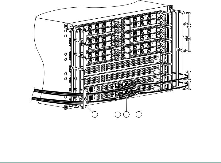
4 Connect the Router to the Network
This section provides information about cables and ports and attaching the router to the network.
•Console and Auxiliary Port Cable Connections, page 13
•Management Ethernet Port Cable Connection, page 13
•Connect the Shared Port Adapter Cables, page 14
•Install the Cables in the Cable-Management Bracket, page 15
Console and Auxiliary Port Cable Connections
This section describes how to attach a cable to the console or auxiliary ports on the Cisco ASR 1006 Router. The Cisco ASR 1006 Router uses RJ-45 ports for both the auxiliary port and console port to attach a modem or console terminal.
The console DCE-mode port connects a console terminal and a DTE-mode auxiliary port connects a modem or other DCE device to your router.
Note Both the console and the auxiliary ports are asynchronous serial ports; any devices connected to these ports must be capable of asynchronous transmission. (Asynchronous is the most common type of serial device; for example, most modems are asynchronous devices.)
Step 1 Before connecting a terminal to the console port, configure the terminal to match the router console port as follows: 9600 baud, 8 data bits, no parity, 1 stop bits. See Figure 8 for console and auxiliary port connector location.
Step 2 After you establish normal router operation, you can disconnect the terminal.
Note For console and auxiliary port pinouts, see Appendix A, Cisco ASR 1000 Series routers Specifications, in the Cisco ASR 1000 Series Aggregation Services Routers Hardware Installation and Initial Configuration Guide.
Management Ethernet Port Cable Connection
Before you can use the console interface on the router using a terminal or PC, you must perform the following steps:
Step 1 Configure your terminal emulation software with the following settings: 9600 bits per second (bps), 8 data bits, No parity, one stop bit, No flow control.
Note For information about how to change the default settings to meet the requirements of your terminal or host, refer to the Cisco IOS Terminal Services Configuration Guide.
Step 2 Connect a terminal or PC to the console port using the cable and adapters provided in the accessory kit that shipped with your Cisco ASR 1006 Router:
– Place the console port mode switch in the in position (factory default).
13
–Connect to the port using the RJ-45-to-RJ-45 cable and RJ-45-to-DB-25 DTE adapter or using the RJ-45-to-DB-9 DTE adapter.
Figure 8 Management Ethernet Port Connectors
|
|
|
|
C /A |
|
|
C |
/A |
A/L |
C |
/A |
A |
/L |
3 |
A |
/L |
|
|
2 |
|
|
|
||
|
|
1 |
|
C /A |
0 |
|
C |
/A |
A/L |
C |
/A |
A |
/L |
3 |
A |
/L |
|
|
2 |
|
|
|
||
|
|
1 |
|
|
0 |
|
|
|
|
|
|
|
|
C/A |
|
|
C |
/A |
A/L |
C |
/A |
A |
/L |
|
3 |
|
|
|
|||
A |
/L |
|
|
2 |
|
|
|
|
|
||
|
|
1 |
|
C/A |
|
0 |
|
C |
/A |
A/L |
|
C/A |
A |
/L |
|
3 |
|
A |
/L |
|
|
2 |
|
|
|
1 |
|
|
|
0 |
|
|
|
|
|
|
|
|
|
C/A |
|
|
|
C |
/A |
A |
/L |
C |
/A |
A |
/L |
|
3 |
|
|
|
|||
A |
/L |
|
|
2 |
|
|
|
|
|
||
|
|
1 |
|
C/A |
|
0 |
|
C |
/A |
A |
/L |
C |
/A |
A |
/L |
3 |
|
|
|||
A |
/L |
|
|
2 |
|
|
|
||
|
|
1 |
|
|
0 |
|
|
|
|
|
/L |
T A |
A |
S |
|
|
SPA-4XOC3 |
-POS |
|
|
C |
/A |
|
|
T U |
S |
|
|
|
|
||
|
/L |
|
S |
T A |
|
A |
|
|
|
||
|
|
SPA-4XOC3 |
-POS |
|
|
C |
/A |
|
|
T U |
S |
|
|
|
|
||
A/L |
|
S |
T A |
|
|
|
|
|
|||
|
|
SPA-4XOC3 |
-POS |
|
|
C |
/A |
|
|
TUS |
|
|
|
|
|||
|
/L |
|
S |
T A |
|
A |
|
|
|
||
|
|
SPA-4XOC3 |
-POS |
|
|
C |
/A |
|
|
T U |
S |
A/L |
|
S |
T A |
|
|
|
|
|
|||
|
|
SPA-4XOC3 |
-POS |
|
|
|
|
|
|
|
|
C |
/A |
|
|
T U |
S |
|
|
|
|
||
A/L |
|
S |
T A |
|
|
|
|
|
|||
|
|
SPA-4XOC3 |
-POS |
|
|
|
|
|
|
|
|
C/A |
|
A/ |
L |
|
|
|
1 |
0 |
|
C/A |
|
A/L |
|
|
1 |
0 |
|
C/A |
|
A/L |
|
|
1 |
0 |
|
C/A |
|
A/ |
L |
|
1 |
0 |
|
C/A |
|
A/ |
L |
|
1 |
0 |
|
A/L |
|
|
|
2 |
|
|
C/A |
|
C |
/A |
/L |
A |
||
A |
/L |
|
|
2 |
|
|
C/A |
|
C |
/A |
/L |
A |
||
A/L |
|
|
|
2 |
|
|
C/A |
|
C |
/A |
/L |
A |
||
A/L |
|
|
|
2 |
|
|
C/A |
|
C |
/A |
/L |
A |
||
A/ |
L |
|
|
|
|
|
2 |
|
3 |
|
|
|
|
|
C |
/A |
|
|
T U |
S |
A/L |
|
S |
T A |
|
|
|
|
|
|||
|
|
SPA-4XOC3 |
-POS |
|
|
|
|
|
|
|
|
3 |
|
|
|
|
|
C |
/A |
|
|
T U |
S |
A/L |
|
S |
T A |
|
|
|
|
|
|||
|
|
SPA-4XOC3 |
-POS |
|
|
|
|
|
|
|
|
3 |
|
|
|
|
|
C |
/A |
|
|
T U |
S |
|
|
|
|
||
A/L |
|
S |
T A |
|
|
|
|
|
|||
|
|
SPA-4XOC3 |
-POS |
|
|
3 |
|
|
|
|
|
C |
/A |
|
|
T U |
S |
|
|
|
|
||
A/L |
|
S |
T A |
|
|
|
|
|
|||
|
|
SPA-4XOC3 |
-POS |
|
|
3 |
|
|
|
|
|
4 |
3 |
2 |
1 |
280086
1 |
AUXiliary connection |
3 |
BITS port |
|
|
|
|
2 |
MGMT Ethernet port |
4 |
Cable-management U feature device |
|
|
|
|
Step 3 Insert an Ethernet RJ-45 cable into the MGMT ETHERNET port.
Step 4 Insert the other end of the RJ-45 cable to your management device or network.
Step 5 Configure to a fixed speed through the command line interface (CLI) commands.
Connect the Shared Port Adapter Cables
The instructions for connecting the cables for the shared port adapter installed in the Cisco ASR 1006 Router are contained in the Cisco ASR 1000 Series Aggregation Services Routers SPA and SIP Hardware Installation Guide.
14
Loading...