


 Loading...
Cisco 860 Series, Cisco 880 Series, and Cisco 890 Series Integrated Services Routers Hardware Installation Guide
Cisco Systems, Inc.
www.cisco.com
Cisco has more than 200 offices worldwide. Addresses, phone numbers, and fax numbers are listed on the Cisco website at www.cisco.com/go/offices.
Text Part Number: OL-16215-11
Last Revised: December 10, 2013
THE SPECIFICATIONS AND INFORMATION REGARDING THE PRODUCTS IN THIS MANUAL ARE SUBJECT TO CHANGE WITHOUT NOTICE. ALL STATEMENTS, INFORMATION, AND RECOMMENDATIONS IN THIS MANUAL ARE BELIEVED TO BE ACCURATE BUT ARE PRESENTED WITHOUT WARRANTY OF ANY KIND, EXPRESS OR IMPLIED. USERS MUST TAKE FULL RESPONSIBILITY FOR THEIR APPLICATION OF ANY PRODUCTS.
THE SOFTWARE LICENSE AND LIMITED WARRANTY FOR THE ACCOMPANYING PRODUCT ARE SET FORTH IN THE INFORMATION PACKET THAT SHIPPED WITH THE PRODUCT AND ARE INCORPORATED HEREIN BY THIS REFERENCE. IF YOU ARE UNABLE TO LOCATE THE SOFTWARE LICENSE OR LIMITED WARRANTY, CONTACT YOUR CISCO REPRESENTATIVE FOR A COPY.
The following information is for FCC compliance of Class A devices: This equipment has been tested and found to comply with the limits for a Class A digital device, pursuant to part 15 of the FCC rules. These limits are designed to provide reasonable protection against harmful interference when the equipment is operated in a commercial environment. This equipment generates, uses, and can radiate radio-frequency energy and, if not installed and used in accordance with the instruction manual, may cause harmful interference to radio communications. Operation of this equipment in a residential area is likely to cause harmful interference, in which case users will be required to correct the interference at their own expense.
The following information is for FCC compliance of Class B devices: The equipment described in this manual generates and may radiate radio-frequency energy. If it is not installed in accordance with Cisco’s installation instructions, it may cause interference with radio and television reception. This equipment has been tested and found to comply with the limits for a Class B digital device in accordance with the specifications in part 15 of the FCC rules. These specifications are designed to provide reasonable protection against such interference in a residential installation. However, there is no guarantee that interference will not occur in a particular installation.
Modifying the equipment without Cisco’s written authorization may result in the equipment no longer complying with FCC requirements for Class A or Class B digital devices. In that event, your right to use the equipment may be limited by FCC regulations, and you may be required to correct any interference to radio or television communications at your own expense.
You can determine whether your equipment is causing interference by turning it off. If the interference stops, it was probably caused by the Cisco equipment or one of its peripheral devices. If the equipment causes interference to radio or television reception, try to correct the interference by using one or more of the following measures:
•Turn the television or radio antenna until the interference stops.
•Move the equipment to one side or the other of the television or radio.
•Move the equipment farther away from the television or radio.
•Plug the equipment into an outlet that is on a different circuit from the television or radio. (That is, make certain the equipment and the television or radio are on circuits controlled by different circuit breakers or fuses.)
Modifications to this product not authorized by Cisco Systems, Inc. could void the FCC approval and negate your authority to operate the product.
The Cisco implementation of TCP header compression is an adaptation of a program developed by the University of California, Berkeley (UCB) as part of UCB’s public domain version of the UNIX operating system. All rights reserved. Copyright © 1981, Regents of the University of California.
NOTWITHSTANDING ANY OTHER WARRANTY HEREIN, ALL DOCUMENT FILES AND SOFTWARE OF THESE SUPPLIERS ARE PROVIDED “AS IS” WITH ALL FAULTS. CISCO AND THE ABOVE-NAMED SUPPLIERS DISCLAIM ALL WARRANTIES, EXPRESSED OR IMPLIED, INCLUDING, WITHOUT LIMITATION, THOSE OF MERCHANTABILITY, FITNESS FOR A PARTICULAR PURPOSE AND NONINFRINGEMENT OR ARISING FROM A COURSE OF DEALING, USAGE, OR TRADE PRACTICE.
IN NO EVENT SHALL CISCO OR ITS SUPPLIERS BE LIABLE FOR ANY INDIRECT, SPECIAL, CONSEQUENTIAL, OR INCIDENTAL DAMAGES, INCLUDING, WITHOUT LIMITATION, LOST PROFITS OR LOSS OR DAMAGE TO DATA ARISING OUT OF THE USE OR INABILITY TO USE THIS MANUAL, EVEN IF CISCO OR ITS SUPPLIERS HAVE BEEN ADVISED OF THE POSSIBILITY OF SUCH DAMAGES.
Cisco and the Cisco logo are trademarks or registered trademarks of Cisco and/or its affiliates in the U.S. and other countries. To view a list of Cisco trademarks, go to this URL: www.cisco.com/go/trademarks. Third-party trademarks mentioned are the property of their respective owners. The use of the word partner does not imply a partnership relationship between Cisco and any other company. (1110R)
Any Internet Protocol (IP) addresses used in this document are not intended to be actual addresses. Any examples, command display output, and figures included in the document are shown for illustrative purposes only. Any use of actual IP addresses in illustrative content is unintentional and coincidental.
Cisco 860 Series, Cisco 880 Series, and Cisco 890 Series Integrated Services Routers Hardware Installation Guide
© 2013 Cisco Systems, Inc. All rights reserved.

REVIEW DRAFT —CISCO CONFIDENTIAL
|
|
|
|
|
|
|
|
|
C O N T E N T S |
||||
|
|
Preface i |
|
|
|
|
|
|
|
|
|
|
|
|
|
Objective |
i |
|
|
|
|
|
|
|
|
|
|
|
|
Audience |
i |
|
|
|
|
|
|
|
|
|
|
|
|
Organization ii |
|
|
|
|
|
|
|
|
|
|
|
|
|
Conventions |
ii |
|
|
|
|
|
|
|
|
|
|
|
|
Related Documentation |
ix |
|
|
|
|
|
|
|
|||
|
|
Searching Cisco Documents |
x |
|
|
|
|
|
|
||||
|
|
Obtaining Documentation and Submitting a Service Request |
x |
||||||||||
|
Product Overview |
|
|
|
|
|
|
|
|
|
|||
C H A P T E R 1 |
1-1 |
|
|
|
|
|
|
|
|
||||
|
|
General Description |
1-2 |
|
|
|
|
|
|
|
|||
|
|
Cisco 860 Series ISRs |
1-2 |
|
|
|
|
|
|
|
|||
|
|
Cisco 860VAE Series ISRs 1-3 |
|
|
|
|
|
|
|||||
|
|
Interfaces |
1-3 |
|
|
|
|
|
|
|
|
|
|
|
|
IOS Images |
1-4 |
|
|
|
|
|
|
|
|
||
|
|
Cisco 860VAE-W-A-K9, Cisco 860VAE-W-E-K9, and |
|
|
|
|
|||||||
|
|
Cisco 860VAE-POE-W-A-K9 ISRs |
1-6 |
|
|
|
|
|
|||||
|
|
Model-Specific Features |
1-6 |
|
|
|
|
|
|
||||
|
|
Common Features |
1-6 |
|
|
|
|
|
|
|
|||
|
|
External Interfaces |
1-7 |
|
|
|
|
|
|
||||
|
|
USB Interface |
1-7 |
|
|
|
|
|
|
|
|||
|
|
LED Indicators |
1-8 |
|
|
|
|
|
|
|
|||
|
|
Cisco 880 Series ISRs |
1-11 |
|
|
|
|
|
|
|
|||
|
|
Cisco 880 Series Data Routers |
1-11 |
|
|
|
|
|
|||||
|
|
Cisco 880 Series Voice and Data Routers |
1-14 |
|
|
|
|
||||||
|
|
Cisco 881 SRST and Cisco 888 SRST |
1-14 |
|
|
|
|
||||||
|
|
Cisco 881-V, Cisco 887VA-V, and Cisco 887VA-V-W |
1-18 |
|
|
|
|||||||
|
|
Cisco 880 Series with Embedded WLAN Antennas 1-20 |
|
|
|
|
|||||||
|
|
Cisco 887VA-WD |
1-20 |
|
|
|
|
|
|
||||
|
|
C881WD |
1-21 |
|
|
|
|
|
|
|
|||
|
|
Cisco 890 Series ISRs |
1-22 |
|
|
|
|
|
|
|
|||
|
|
Cisco 891, Cisco 892, and Cisco 892F |
1-22 |
|
|
|
|
||||||
|
|
Cisco 892FSP, Cisco 896VA, Cisco 897VA, and Cisco 898EA 1-25 |
|||||||||||
|
|
Hardware Features |
1-32 |
|
|
|
|
|
|
|
|||
|
|
Cisco 860 Series, Cisco 880 Series, and Cisco 890 Series Integrated Services Routers Hardware Installation Guide |
|
|
|
||||||||
|
|
|
|||||||||||
|
|
|
|
|
|
|
|
|
|
|
|
|
|
|
OL-16215-11 |
|
|
|
|
|
|
|
|
|
|
3 |
|
|
|
|
|
|
|
|
|
|
|
|
|
||

Contents
REVIEW DRAFT—CISCO CONFIDENTIAL
Kensington Lock |
1-32 |
|
|
|
|||
Reset Button |
1-32 |
|
|
|
|||
Cisco 860VAE Routers—Custom Configuration File 1-32 |
|
||||||
Custom Configuration File for Cisco 892FSP, 896VA, 897VA, and Cisco 898EA |
1-33 |
||||||
LEDs |
1-35 |
|
|
|
|
|
|
Shared LEDs on the Cisco 881-V and Cisco 887VA-V Voice and Data Routers |
1-40 |
||||||
Memory |
1-41 |
|
|
|
|
|
|
USB Port |
1-42 |
|
|
|
|
|
|
Fan |
1-43 |
|
|
|
|
|
|
Power Supply |
1-43 |
|
|
|
|||
Power over Ethernet Module |
1-43 |
|
|
||||
3G Cellular Data WAN Connectivity |
1-44 |
|
|||||
Wireless LAN Connectivity |
1-45 |
|
|
||||
Supported Cisco Radio Antennas |
1-46 |
|
|||||
Small Form-Factor Pluggable Port 1-46 |
|
||||||
Feature Summary |
1-47 |
|
|
|
|||
C H A P T E R |
2 |
|
Installing the Router |
2-1 |
|
|
|
|
|||
|
|
|
|
|
Equipment, Tools, and Connections |
2-2 |
|
||||
|
|
|
|
|
Items Shipped with your Router |
2-2 |
|
||||
|
|
|
|
|
Additional Items |
2-2 |
|
|
|
||
|
|
|
|
|
Connections |
2-3 |
|
|
|
|
|
|
|
|
|
|
Ethernet Devices |
2-3 |
|
|
|
||
|
|
|
|
|
Installing the Router |
2-3 |
|
|
|
|
|
|
|
|
|
|
Warnings 2-4 |
|
|
|
|
|
|
|
|
|
|
|
Installing Antennas |
2-4 |
|
|
|
||
|
|
|
|
|
Installing on a Table |
2-7 |
|
|
|
||
|
|
|
|
|
Mounting on a Wall |
2-8 |
|
|
|
||
|
|
|
|
|
Installing in a Rack |
2-11 |
|
|
|
||
|
|
|
|
|
Installing the Router Ground Connection 2-13 |
||||||
|
|
|
|
|
Installing the FIPS Cover 2-14 |
|
|
|
|||
|
|
|
Connecting the Router |
|
|
|
|
|
|||
C H A P T E R |
3 |
|
3-1 |
|
|
|
|
||||
|
|
|
|
|
Safety Warnings |
3-2 |
|
|
|
|
|
|
|
|
|
|
Preparing to Connect the Router 3-4 |
|
|
|
|||
|
|
|
|
|
Preventing Damage to the Router |
|
3-4 |
|
|||
|
|
|
|
|
Connecting a PC, Server, or Workstation |
3-5 |
|
||||
|
|
|
|
|
Connecting a Phone |
|
3-6 |
|
|
|
|
|
|
|
|
|
Connecting an External Ethernet Switch |
3-7 |
|
||||
|
|
|
|
Cisco 860 Series, Cisco 880 Series, and Cisco 890 Series Integrated Services Routers Hardware Installation Guide |
|||||||
|
|
|
|
||||||||
|
|
|
|
|
|
|
|
|
|
|
|
|
4 |
|
|
|
|
|
|
|
|
OL-16215-11 |
|
|
|
|
|
|
|
|
|
|
|
||

Contents
REVIEW DRAFT —CISCO CONFIDENTIAL
|
|
|
Connecting the V.92 modem Port |
3-8 |
|
|
|
|
|
||||
|
|
|
Connecting a Terminal or PC to the Console Port |
3-9 |
|
|
|
||||||
|
|
|
Terminal Emulator Settings |
3-10 |
|
|
|
|
|
||||
|
|
|
Connecting a Modem to the Auxiliary Port |
3-10 |
|
|
|
|
|||||
|
|
|
Connecting the 3G Card |
|
3-11 |
|
|
|
|
|
|
||
|
|
|
Installing the 3G Adapter for Extended Cable/Antenna 3-17 |
||||||||||
|
|
|
Connecting a Data BRI Port |
3-21 |
|
|
|
|
|
|
|||
|
|
|
Connecting an FE Line to an FE WAN Port |
3-23 |
|
|
|
|
|||||
|
|
|
Connecting a GE Line to an GE WAN Port |
3-24 |
|
|
|
|
|||||
|
|
|
Connecting an xDSL Line |
3-25 |
|
|
|
|
|
|
|||
|
|
|
Connecting Power over Ethernet |
3-27 |
|
|
|
|
|
||||
|
|
|
Connecting the AC Adapter |
3-28 |
|
|
|
|
|
|
|||
|
|
|
Connecting an FXS Line |
|
3-32 |
|
|
|
|
|
|
||
|
|
|
Connecting an FXO Line |
|
3-34 |
|
|
|
|
|
|
||
|
|
|
Connecting a Voice ISDN BRI Line |
3-35 |
|
|
|
|
|
||||
|
|
|
Connecting a Small Form-Factor Pluggable Module |
3-37 |
|
|
|
||||||
|
|
|
Safety Warnings |
3-37 |
|
|
|
|
|
|
|
||
|
|
|
Installing an SFP Module |
3-38 |
|
|
|
|
|
||||
|
|
|
Removing an SFP Module |
3-38 |
|
|
|
|
|
||||
|
|
|
Online Insertion and Removal |
3-39 |
|
|
|
|
|
||||
|
|
|
Verifying Connections |
3-40 |
|
|
|
|
|
|
|
||
|
|
Initial Configuration 4-1 |
|
|
|
|
|
|
|
|
|
||
C H A P T E R |
4 |
|
|
|
|
|
|
|
|
|
|||
|
|
|
Cisco Configuration Professional Express |
4-1 |
|
|
|
|
|||||
|
|
|
Cisco IOS CLI |
4-1 |
|
|
|
|
|
|
|
|
|
|
|
|
Setup Command Facility |
|
4-3 |
|
|
|
|
|
|
|
|
|
|
|
Verifying the Initial Configuration |
4-5 |
|
|
|
|
|
||||
|
|
|
Initial Configuration of the Wireless Access Point |
4-6 |
|
|
|
||||||
|
|
Technical Specifications |
|
|
|
|
|
|
|
|
|
||
A P P E N D I X |
A |
|
A-1 |
|
|
|
|
|
|
|
|||
|
|
|
Router Specifications |
A-2 |
|
|
|
|
|
|
|
||
|
|
|
All Models Except Cisco 860VAE Series A-2 |
|
|
|
|
||||||
|
|
|
Cisco 860VAE Series |
A-3 |
|
|
|
|
|
|
|||
|
|
|
Cisco 860VAE-W-A-K9, Cisco 860VAE-W-E-K9, and Cisco 860VAE-POE-W-A-K9 Series A-4 |
||||||||||
|
|
|
Power Supply |
A-5 |
|
|
|
|
|
|
|
|
|
|
|
|
Wireless Access Point |
|
A-5 |
|
|
|
|
|
|
|
|
|
|
|
FE and GE Port Pinouts |
|
A-6 |
|
|
|
|
|
|
|
|
|
|
|
Cisco 860 Series, Cisco 880 Series, and Cisco 890 Series Integrated Services Routers Hardware Installation Guide |
|
|
|
|||||||
|
|
|
|
||||||||||
|
|
|
|
|
|
|
|
|
|
|
|
|
|
|
OL-16215-11 |
|
|
|
|
|
|
|
|
|
5 |
|
|
|
|
|
|
|
|
|
|
|
|
|
|||

Contents
REVIEW DRAFT—CISCO CONFIDENTIAL
Console and Auxiliary Port Connector Pinouts A-7
FXS and FXO Port Connector Pinouts A-7
VDSL2 Port Connector Pinouts |
A-7 |
|
ADSL2+ Port Connector Pinouts |
A-8 |
|
V.92 Port Connector Pinouts |
A-8 |
|
G.SHDSL Port Connector Pinouts |
A-8 |
|
Data BRI Port Connector Pinouts |
A-9 |
|
Voice ISDN BRI Interface Pin Numbers and Functions A-10 |
||
SFP Port Connector Pinouts |
A-10 |
|
Cable Specifications A-11 |
|
|
Ethernet Cable Specifications |
A-11 |
|
Maximum Cable Length |
A-11 |
|
Cisco 860 Series, Cisco 880 Series, and Cisco 890 Series Integrated Services Routers Hardware Installation Guide
6 |
OL-16215-11 |
|
|

Preface
This preface describes the objectives, audience, organization, and conventions of this guide, and describes related documents that have additional information. It contains the following sections:
•Objective, page i
•Audience, page i
•Organization, page ii
•Conventions, page ii
•Related Documentation, page ix
•Searching Cisco Documents, page x
•Obtaining Documentation and Submitting a Service Request, page x
Objective
This guide provides an overview and explains how to install, connect, and perform initial configuration for the wireless and nonwireless Cisco 860 series, Cisco 880 series, and Cisco 890 series Integrated Services Routers (ISRs). Some information may not apply to your particular router model.
For warranty, service, and support information, see the “Cisco One-Year Limited Hardware Warranty Terms” section in Readme First for the Cisco 800 Series Integrated Services Routers that was shipped with your router.
Audience
This guide is intended for Cisco equipment providers who are technically knowledgeable and familiar with Cisco routers and Cisco IOS software and features.
Cisco 860 Series, Cisco 880 Series, and Cisco 890 Series Integrated Services Routers Hardware Installation Guide
|
OL-16215-11 |
i |
|

Organization
This guide is organized into the following chapters and appendix.
Chapter |
Name |
Description |
|
|
|
Chapter 1 |
Chapter 1, “Product Overview” |
Describes the router models and the |
|
|
hardware features available. |
|
|
|
Chapter 2 |
Chapter 2, “Installing the Router” |
Lists the items shipped with the router, the |
|
|
equipment and tools necessary for |
|
|
installing the router, the safety warnings |
|
|
and guidelines, and the procedures for |
|
|
installing the router. |
|
|
|
Chapter 3 |
Chapter 3, “Connecting the Router” |
Describes typical connections for the |
|
|
router, procedures for connecting the |
|
|
router to various devices, and how to |
|
|
verify the connections. |
|
|
|
Chapter 4 |
Chapter 4, “Initial Configuration” |
Provides the procedures for initially |
|
|
configuring the router settings. |
|
|
|
Appendix A |
Appendix A, “Technical Specifications” |
Provides the router, port, and cabling |
|
|
specifications. |
|
|
|
Conventions
This section describes the conventions used in this guide.
Note Means reader take note. Notes contain helpful suggestions or references to additional information and material.
Caution This symbol means reader be careful. In this situation, you might do something that could result in equipment damage or loss of data.
Tip Means the following information will help you solve a problem. The tip information might not be troubleshooting or even an action, but could be useful information.
Cisco 860 Series, Cisco 880 Series, and Cisco 890 Series Integrated Services Routers Hardware Installation Guide
|
ii |
OL-16215-11 |
|
|
|

Warning IMPORTANT SAFETY INSTRUCTIONS
This warning symbol means danger. You are in a situation that could cause bodily injury. Before you work on any equipment, be aware of the hazards involved with electrical circuitry and be familiar with standard practices for preventing accidents. Use the statement number provided at the end of each warning to locate its translation in the translated safety warnings that accompanied this device. Statement 1071
SAVE THESE INSTRUCTIONS
Waarschuwing BELANGRIJKE VEILIGHEIDSINSTRUCTIES
Dit waarschuwingssymbool betekent gevaar. U verkeert in een situatie die lichamelijk letsel kan veroorzaken. Voordat u aan enige apparatuur gaat werken, dient u zich bewust te zijn van de bij elektrische schakelingen betrokken risico's en dient u op de hoogte te zijn van de standaard praktijken om ongelukken te voorkomen. Gebruik het nummer van de verklaring onderaan de waarschuwing als u een vertaling van de waarschuwing die bij het apparaat wordt geleverd, wilt raadplegen.
BEWAAR DEZE INSTRUCTIES
Varoitus TÄRKEITÄ TURVALLISUUSOHJEITA
Tämä varoitusmerkki merkitsee vaaraa. Tilanne voi aiheuttaa ruumiillisia vammoja. Ennen kuin käsittelet laitteistoa, huomioi sähköpiirien käsittelemiseen liittyvät riskit ja tutustu onnettomuuksien yleisiin ehkäisytapoihin. Turvallisuusvaroitusten käännökset löytyvät laitteen mukana toimitettujen käännettyjen turvallisuusvaroitusten joukosta varoitusten lopussa näkyvien lausuntonumeroiden avulla.
SÄILYTÄ NÄMÄ OHJEET
Attention IMPORTANTES INFORMATIONS DE SÉCURITÉ
Ce symbole d'avertissement indique un danger. Vous vous trouvez dans une situation pouvant entraîner des blessures ou des dommages corporels. Avant de travailler sur un équipement, soyez conscient des dangers liés aux circuits électriques et familiarisez-vous avec les procédures couramment utilisées pour éviter les accidents. Pour prendre connaissance des traductions des avertissements figurant dans les consignes de sécurité traduites qui accompagnent cet appareil, référez-vous au numéro de l'instruction situé à la fin de chaque avertissement.
CONSERVEZ CES INFORMATIONS
Warnung WICHTIGE SICHERHEITSHINWEISE
Dieses Warnsymbol bedeutet Gefahr. Sie befinden sich in einer Situation, die zu Verletzungen führen kann. Machen Sie sich vor der Arbeit mit Geräten mit den Gefahren elektrischer Schaltungen und den üblichen Verfahren zur Vorbeugung vor Unfällen vertraut. Suchen Sie mit der am Ende jeder Warnung angegebenen Anweisungsnummer nach der jeweiligen Übersetzung in den übersetzten Sicherheitshinweisen, die zusammen mit diesem Gerät ausgeliefert wurden.
BEWAHREN SIE DIESE HINWEISE GUT AUF.
Cisco 860 Series, Cisco 880 Series, and Cisco 890 Series Integrated Services Routers Hardware Installation Guide
|
OL-16215-11 |
iii |
|

Avvertenza IMPORTANTI ISTRUZIONI SULLA SICUREZZA
Questo simbolo di avvertenza indica un pericolo. La situazione potrebbe causare infortuni alle persone. Prima di intervenire su qualsiasi apparecchiatura, occorre essere al corrente dei pericoli relativi ai circuiti elettrici e conoscere le procedure standard per la prevenzione di incidenti. Utilizzare il numero di istruzione presente alla fine di ciascuna avvertenza per individuare le traduzioni delle avvertenze riportate in questo documento.
CONSERVARE QUESTE ISTRUZIONI
Advarsel VIKTIGE SIKKERHETSINSTRUKSJONER
Dette advarselssymbolet betyr fare. Du er i en situasjon som kan føre til skade på person. Før du begynner å arbeide med noe av utstyret, må du være oppmerksom på farene forbundet med elektriske kretser, og kjenne til standardprosedyrer for å forhindre ulykker. Bruk nummeret i slutten av hver advarsel for å finne oversettelsen i de oversatte sikkerhetsadvarslene som fulgte med denne enheten.
TA VARE PÅ DISSE INSTRUKSJONENE
Aviso INSTRUÇÕES IMPORTANTES DE SEGURANÇA
Este símbolo de aviso significa perigo. Você está em uma situação que poderá ser causadora de lesões corporais. Antes de iniciar a utilização de qualquer equipamento, tenha conhecimento dos perigos envolvidos no manuseio de circuitos elétricos e familiarize-se com as práticas habituais de prevenção de acidentes. Utilize o número da instrução fornecido ao final de cada aviso para localizar sua tradução nos avisos de segurança traduzidos que acompanham este dispositivo.
GUARDE ESTAS INSTRUÇÕES
¡Advertencia! INSTRUCCIONES IMPORTANTES DE SEGURIDAD
Este símbolo de aviso indica peligro. Existe riesgo para su integridad física. Antes de manipular cualquier equipo, considere los riesgos de la corriente eléctrica y familiarícese con los procedimientos estándar de prevención de accidentes. Al final de cada advertencia encontrará el número que le ayudará a encontrar el texto traducido en el apartado de traducciones que acompaña a este dispositivo.
GUARDE ESTAS INSTRUCCIONES
Varning! VIKTIGA SÄKERHETSANVISNINGAR
Denna varningssignal signalerar fara. Du befinner dig i en situation som kan leda till personskada. Innan du utför arbete på någon utrustning måste du vara medveten om farorna med elkretsar och känna till vanliga förfaranden för att förebygga olyckor. Använd det nummer som finns i slutet av varje varning för att hitta dess översättning i de översatta säkerhetsvarningar som medföljer denna anordning.
SPARA DESSA ANVISNINGAR
Cisco 860 Series, Cisco 880 Series, and Cisco 890 Series Integrated Services Routers Hardware Installation Guide
|
iv |
OL-16215-11 |
|
|
|
Cisco 860 Series, Cisco 880 Series, and Cisco 890 Series Integrated Services Routers Hardware Installation Guide
|
OL-16215-11 |
v |
|
Aviso INSTRUÇÕES IMPORTANTES DE SEGURANÇA
Este símbolo de aviso significa perigo. Você se encontra em uma situação em que há risco de lesões corporais. Antes de trabalhar com qualquer equipamento, esteja ciente dos riscos que envolvem os circuitos elétricos e familiarize-se com as práticas padrão de prevenção de acidentes. Use o número da declaração fornecido ao final de cada aviso para localizar sua tradução nos avisos de segurança traduzidos que acompanham o dispositivo.
GUARDE ESTAS INSTRUÇÕES
Advarsel VIGTIGE SIKKERHEDSANVISNINGER
Dette advarselssymbol betyder fare. Du befinder dig i en situation med risiko for legemesbeskadigelse. Før du begynder arbejde på udstyr, skal du være opmærksom på de involverede risici, der er ved elektriske kredsløb, og du skal sætte dig ind i standardprocedurer til undgåelse af ulykker. Brug erklæringsnummeret efter hver advarsel for at finde oversættelsen i de oversatte advarsler, der fulgte med denne enhed.
GEM DISSE ANVISNINGER
Cisco 860 Series, Cisco 880 Series, and Cisco 890 Series Integrated Services Routers Hardware Installation Guide
|
vi |
OL-16215-11 |
|
|
|

Cisco 860 Series, Cisco 880 Series, and Cisco 890 Series Integrated Services Routers Hardware Installation Guide
|
OL-16215-11 |
vii |
|
Warning When installing the product, please use the provided or designated connection cables/power cables/AC adaptors. Using any other cables/adaptors could cause a malfunction or a fire. Electrical Appliance and Material Safety Law prohibits the use of UL-certified cables (that have the “UL” shown on the code) for any other electrical devices than products designated by CISCO. The use of cables that are certified by Electrical Appliance and Material Safety Law (that have “PSE” shown on the code) is not limited to CISCO-designated products. Statement 371
Warning There is the danger of explosion if the battery is replaced incorrectly. Replace the battery only with the same or equivalent type recommended by the manufacturer. Dispose of used batteries according to the manufacturer’s instructions. Statement 1015
Warning Do not use this product near water; for example, near a bath tub, wash bowl, kitchen sink or laundry tub, in a wet basement, or near a swimming pool. Statement 1035
Warning Never install telephone jacks in wet locations unless the jack is specifically designed for wet locations. Statement 1036
Warning Never touch uninsulated telephone wires or terminals unless the telephone line has been disconnected at the network interface. Statement 1037
Warning Avoid using a telephone (other than a cordless type) during an electrical storm. There may be a remote risk of electric shock from lightning. Statement 1038
Cisco 860 Series, Cisco 880 Series, and Cisco 890 Series Integrated Services Routers Hardware Installation Guide
|
viii |
OL-16215-11 |
|
|
|

Warning Only trained and qualified personnel should be allowed to install, replace, or service this equipment.
Statement 1030
Warning Read the installation instructions before connecting the system to the power source. Statement 1004
Warning Ultimate disposal of this product should be handled according to all national laws and regulations.
Statement 1040
Related Documentation
In addition to the Cisco 860 series, Cisco 880 series, and Cisco 890 series ISR Hardware Installation Guide (this document), the Cisco 860 series, Cisco 880 series, and Cisco 890 series ISR documentation set includes the following documents:
•Regulatory Compliance and Safety Information for Cisco 800 Series
•Cisco 860 Series, Cisco 880 Series, and Cisco 890 Series Integrated Services Routers Software Configuration Guide
•Software Activation on Cisco Integrated Services Routers and Cisco Integrated Service Routers G2
•Cisco IOS Software Activation Configuration Guide
•Declarations of Conformity and Regulatory Information for Cisco Access Products with 802.11a/b/g and 802.11b/g Radios
•Cisco IOS Release Notes
•Cisco IOS Quality of Service Solutions Command Reference, Release 12.4T
•Cisco IOS Security Configuration Guide, Release 12.4T
•Cisco IOS Security Command Reference, Release 12.4T
•Cisco IOS Command Reference for Cisco Aironet Access Points and Bridges, versions 12.4(10b) JA and 12.3(8) JEC
•Wireless LAN Controllers
•Unified Wireless LAN Access Points
•Cisco IOS Voice Port Configuration Guide
•SCCP Controlled Analog (FXS) Ports with Supplementary Features in Cisco IOS Gateways
•Cisco CP Express User’s Guide
Cisco 860 Series, Cisco 880 Series, and Cisco 890 Series Integrated Services Routers Hardware Installation Guide
|
OL-16215-11 |
ix |
|

Searching Cisco Documents
To search a HTML document using a web browser, press Ctrl-F (Windows) or Cmd-F (Apple). In most browsers, the option to search whole words only, invoke case sensitivity, or search forward and backward is also available.
To search a PDF document in Adobe Reader, use the basic Find toolbar (Ctrl-F) or the Full Reader Search window (Shift-Ctrl-F). Use the Find toolbar to find words or phrases within a specific document. Use the Full Reader Search window to search multiple PDF files simultaneously and to change case sensitivity and other options. Adobe Reader’s online help has more information about how to search PDF documents.
Obtaining Documentation and Submitting a Service Request
For information on obtaining documentation, submitting a service request, and gathering additional information, see the monthly What’s New in Cisco Product Documentation, which also lists all new and revised Cisco technical documentation:
http://www.cisco.com/en/US/docs/general/whatsnew/whatsnew.html
Subscribe to the What’s New in Cisco Product Documentation as an RSS feed and set content to be delivered directly to your desktop using a reader application. The RSS feeds are a free service. Cisco currently supports RSS Version 2.0.y
Cisco 860 Series, Cisco 880 Series, and Cisco 890 Series Integrated Services Routers Hardware Installation Guide
|
x |
OL-16215-11 |
|
|
|

C H A P T E R 1
Product Overview
Note
Note
Note
This chapter provides an overview of the features available for the Cisco 860 series, Cisco 880 series, and Cisco 890 series Integrated Services Routers (ISRs), and contains the following sections:
•General Description, page 1-2
•Cisco 860 Series ISRs, page 1-2
•Cisco 860VAE Series ISRs, page 1-3
•Cisco 860VAE-W-A-K9, Cisco 860VAE-W-E-K9, and Cisco 860VAE-POE-W-A-K9 ISRs, page 1-6
•Cisco 880 Series ISRs, page 1-11
•Cisco 890 Series ISRs, page 1-22
•Hardware Features, page 1-32
For compliance and safety information, see Regulatory Compliance and Safety Information Roadmap that ships with the router and Regulatory Compliance and Safety Information for Cisco 800 Series.
Some illustrations in this document show a wireless router. Both wireless and nonwireless models are available in the Cisco 860 series, Cisco 880 series, and Cisco 890 series ISRs. Port and feature locations are similar for both wireless and nonwireless routers.
Throughout this document the term VDSL refers to support for VDSL2 (ITU G.993.2) and ADSL refers to support for ADSL, ADSL2, & ADSL2+ (ITU G.992.1, G.992.3, & G.992.5).
Cisco 860 Series, Cisco 880 Series, and Cisco 890 Series Integrated Services Routers Hardware Installation Guide
|
OL-16215-11 |
1-1 |
|
|
|
Chapter 1 Product Overview
General Description
General Description
The Cisco 860 series, Cisco 880 series, and Cisco 890 series ISRs provide data, voice, Wi-Fi CERTIFIED™ wireless access point (AP), integrated Virtual Private Network (VPN), and backup capabilities to corporate teleworkers and to remote and small offices with fewer than 20 users. These routers are capable of bridging and multiprotocol routing between LAN and WAN ports. The routers provide advanced features, such as high speed DSL (G.SHDSL, ADSL, or VDSL), 802.11n, quality of service (QoS), firewall, antivirus protection, and Secure Socket Layer (SSL). The Cisco 860VAE, 886VA and 887VA series routers have the additional capability of DSL Multi-mode (VDSL/ADSL).
The Cisco 860 series, Cisco 880 series, and Cisco 890 series ISRs have a desktop form factor with built-in wall-mount features. The Cisco 890 series ISRs also have optional rack-mount features. These ISRs are powered by an external power supply adapter. The various models differ in the WAN interface and features that they support.
Cisco 860 Series ISRs
The Cisco 860 series ISRs are fixed-configuration data routers that support the following features:
•An integrated 4-port 10/100 Ethernet switch for connecting to the LAN
•A10/100 Fast Ethernet (FE) port for connecting to the WAN.
•Optional, embedded Wi-Fi CERTIFIED™, 802.11b/g/n-compliant wireless AP
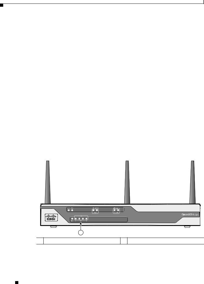
Figure 1-1 shows the front panel details of the Cisco 860 wireless router.
Figure 1-1 Front Panel of the Cisco 860 Series Wireless ISR

 231969
1
1 LEDs
Cisco 860 Series, Cisco 880 Series, and Cisco 890 Series Integrated Services Routers Hardware Installation Guide
1-2 |
OL-16215-11 |
|
|
Chapter 1 Product Overview
Cisco 860VAE Series ISRs
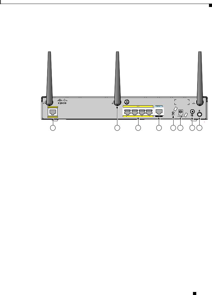
Figure 1-2 shows the back panel details of the Cisco 861 wireless (861W) ISR. Nonwireless routers do not have antennas on the back panel. However, the feature locations are similar for all Cisco 860 series routers.
Figure 1-2 Back Panel of the Cisco 861W ISR
Cisco 861W
WAN |
FE 4
232181
|
1 |
2 |
|
3 |
4 |
5 |
6 |
7 |
8 |
|
|
|
|
|
|
|
|
|
|
1 |
Primary WAN port—10/100 |
|
5 |
Reset button |
|
|
|
|
|
|
|
|
|
|
|
|
|
|
|
2 |
Antenna—captive omnidirectional dipole |
|
6 |
Power connector |
|
|
|
|
|
|
WLAN antenna (wireless models only) |
|
|
|
|
|
|
|
|
|
|
|
|
|
|
|
|
||
3 |
4-port 10/100 Ethernet switch |
|
7 |
Earth ground connection |
|
|
|
||
|
|
|
|
|
|
|
|
||
4 |
Serial port—console or auxiliary |
|
8 |
Kensington security slot |
|
|
|
||
|
|
|
|
|
|
|
|
|
|
Cisco 860VAE Series ISRs
The Cisco 860VAE series ISRs are fixed-configuration data routers. This section describes the features of the products in this series.
Interfaces
Table 1-1 describes the interfaces of the Cisco 860VAE series routers.
Table 1-1 |
Interfaces of the Cisco 860VAE Series ISRs |
|
|
|
|||
|
|
|
|
|
|
|
|
|
|
|
|
|
Model |
|
|
|
|
|
|
|
|
|
|
Interfaces |
|
866VAE |
867VAE |
|
866VAE-K9 |
867VAE-K9 |
|
|
|
|
|
|
|
|
|
4 |
FE1 switch ports |
x |
x |
|
x |
x |
|
1 |
GE2 switch port |
— |
— |
|
x |
x |
|
1 |
GE WAN port |
x |
x |
|
x |
x |
|
|
|
|
|
|
|
|
|
Cisco 860 Series, Cisco 880 Series, and Cisco 890 Series Integrated Services Routers Hardware Installation Guide
|
OL-16215-11 |
1-3 |
|
|
|
Chapter 1 Product Overview
Cisco 860VAE Series ISRs
Table 1-1 |
Interfaces of the Cisco 860VAE Series ISRs (continued) |
|
|||||
|
|
|
|
|
|
|
|
|
|
|
|
|
Model |
|
|
|
|
|
|
|
|
|
|
Interfaces |
|
866VAE |
867VAE |
|
866VAE-K9 |
867VAE-K9 |
|
|
|
|
|
|
|
|
|
1 |
VDSL/ADSL over POTS port |
— |
x |
|
— |
x |
|
|
|
|
|
|
|
|
|
1 |
VDSL/ADSL over ISDN port |
x |
— |
|
x |
— |
|
|
|
|
|
|
|
|
|
1.FE = Fast Ethernet
2.GE = Gigabit Ethernet
Note The Cisco 866VAE, 867VAE, 866VAE-K9, and 867VAE-K9 routers each have two WAN ports. Only one of the two ports can be active at any given time.
IOS Images
Table 1-2 describes the IOS images included in Cisco 860VAE series routers.
Table 1-2 |
IOS Images of the Cisco 860VAE Series ISRs |
|
|
|
||
|
|
|
|
|
|
|
|
|
|
|
Model |
|
|
|
|
|
|
|
|
|
IOS Image |
|
866VAE |
867VAE |
|
866VAE-K9 |
867VAE-K9 |
|
|
|
|
|
|
|
c860vae-ipbasek9-mz |
x |
x |
|
— |
— |
|
|
|
|
|
|
|
|
c860vae-advsecurityk9-mz |
— |
— |
|
x |
x |
|
|
|
|
|
|
|
|
c860vae-advsecurityk9_npe-mz |
— |
— |
|
x |
x |
|
|
|
|
|
|
|
|
Figure 1-3 shows the front panel details of the Cisco 866VAE, Cisco 867VAE, Cisco 866VAE-K9, and Cisco 867VAE-K9 integrated services routers (ISRs).
Figure 1-3 Front Panel of the Cisco 860VAE series ISR
Cisco 860 Series |
246199 |
1
1 LEDs
Cisco 860 Series, Cisco 880 Series, and Cisco 890 Series Integrated Services Routers Hardware Installation Guide
1-4 |
OL-16215-11 |
|
|
Chapter 1 Product Overview
Cisco 860VAE Series ISRs
Figure 1-4 shows the back panel details of the Cisco 866VAE ISR.
Figure 1-4 Back Panel of the Cisco 866VAE ISR
|
|
|
Cisco 866VAE |
|
|
VDSL/ADSL |
WAN |
|
|
LAN |
|
OVER ISDN |
GE0 |
FE 3 |
FE 2 |
FE 1 |
FE 0 |
CONSOLE |
|
12V |
2.5A |
|
RESET |
AUX |
246200 |
|
1 |
2 |
3 |
|
4 |
5 |
6 |
7 |
8 |
9 |
|
|
|
|
|
|
|
|
|
|
|
|
|
1 |
|
xDSL port1 |
|
|
6 |
On/Off switch |
|
|
|
|
|
2 |
|
GE WAN interface |
|
7 |
Power connector |
|
|
|
|
||
|
|
|
|
|
|
|
|
|
|
||
3 |
|
Ethernet LAN FE interfaces (FE0 through |
8 |
Reset button |
|
|
|
|
|
||
|
|
FE3 interfaces) |
|
|
|
|
|
|
|
|
|
|
|
|
|
|
|
|
|
|
|
||
4 |
|
USB port |
|
|
9 |
Kensington security slot |
|
|
|
||
|
|
|
|
|
|
|
|
|
|
|
|
5 |
|
Serial port—console or auxiliary |
|
|
|
|
|
|
|
|
|
|
|
|
|
|
|
|
|
|
|
|
|
1. |
Using RJ-11. |
|
|
|
|
|
|
|
|
|
|
Figure 1-5 shows the back panel details of the Cisco 867VAE-K9.
Figure 1-5 Back Panel of the Cisco 867VAE-K9 ISR
Cisco 867VAE-K9
VDSL/ADSL |
WAN |
LAN |
CONSOLE |
|
12V
 2.5A
2.5A
|
|
|
|
|
|
|
|
|
|
|
RESET |
|
OVER POTS |
|
GE0 |
FE3 |
FE2 |
FE1 |
FE0 |
|
AUX |
|
|
|
284558 |
|
|
|
|
|
|
|
|
|
|
|
|
|
1 |
2 |
|
|
3 |
|
|
4 |
5 |
6 |
7 |
8 |
9 |
1 |
xDSL port |
6 |
On/Off switch |
|
|
|
|
2 |
GE WAN interface |
7 |
Power connector |
|
|
|
|
3 |
Ethernet LAN GE and FE interfaces (GE0 |
8 |
Reset button |
|
interface and FE0 through FE3 interfaces) |
|
|
|
|
|
|
4 |
USB port |
9 |
Kensington security slot |
|
|
|
|
5 |
Serial port—console or auxiliary |
|
|
|
|
|
|
Cisco 860 Series, Cisco 880 Series, and Cisco 890 Series Integrated Services Routers Hardware Installation Guide
|
OL-16215-11 |
1-5 |
|
|
|

Chapter 1 Product Overview
Cisco 860VAE-W-A-K9, Cisco 860VAE-W-E-K9, and Cisco 860VAE-POE-W-A-K9 ISRs
Cisco 860VAE-W-A-K9, Cisco 860VAE-W-E-K9, and
Cisco 860VAE-POE-W-A-K9 ISRs
This section provides a hardware overview of the following Cisco 860VAE Series Integrated Services Routers (ISRs):
•C866VAE-W-E-K9
•C867VAE-W-A-K9
•C867VAE-W-E-K9
•C867VAE-POE-W-A-K9
Model-Specific Features
Table 1-3 describes the features specific to each of these router models:
Table 1-3 |
Model-Specific Router Features |
|
|
|
|
|
|
|
|
|
|
|
|
C866VAE-W-E- |
C867VAE-W-A- |
C867VAE-W-E- |
C867VAE-POE- |
Feature |
|
K9 |
K9 |
K9 |
W-A-K9 |
|
|
|
|
|
|
WAN interface and mode |
One GE port, |
One GE port, |
One GE port, |
One GE port, |
|
|
|
DSL over |
DSL over |
DSL over |
DSL over |
|
|
ISDN, |
POTS, |
POTS, |
POTS, |
|
|
Europe WiFi |
America WiFi |
Europe WiFi |
America WiFi |
|
|
|
|
|
|
Power-over-Ethernet (PoE) |
No |
No |
No |
Yes |
|
|
|
|
|
|
|
Common Features
The following key features are common to each of these router models:
•Dual WAN interface (Gigabit Ethernet [GE] and dual-mode ADSL2+ /VDSL2)
•2.4 GHz wireless LAN (WLAN) interface
•Five Layer 2 LAN switches: two Gigabit Ethernet and three Fast Ethernet
•One USB 2.0 port in high-speed host mode
•One RJ-45 console port (RS-232 interface)
•Support for up to 512 MB DRAM using DDR in 16-bit mode
•Support for 8 MB Serial Peripheral Interface Bus (SPI) flash memory for boot and 128 MB NAND flash memory for storing IOS
•Reset/Recovery switch
•Silent convection cooling—no fan
Cisco 860 Series, Cisco 880 Series, and Cisco 890 Series Integrated Services Routers Hardware Installation Guide
1-6 |
OL-16215-11 |
|
|

Chapter 1 Product Overview
Cisco 860VAE-W-A-K9, Cisco 860VAE-W-E-K9, and Cisco 860VAE-POE-W-A-K9 ISRs
External Interfaces
Figure 1-6 shows the back I/O panel of the Cisco 867VAE-POE-W-A-K9 series router.
Figure 1-6 |
Back I/O Panel |
|
|
|
|
|
|
|
|
|
|
|
|
Cisco 867VAE-POE-W-A-K9 |
|
|
|
VDSL/ADSL |
WAN |
|
|
LAN |
|
|
CONSOLE |
|
|
|
|
|
|
|
|||
|
|
|
|
|
|
|
12V |
2.5A |
|
|
|
|
|
|
|
|
RESET |
OVER POTS |
GE2 |
GE1 |
GE0 |
FE2 |
FE1 |
FE0(POE) |
AUX |
|
360426
Table 1-4 describes the external interfaces included with these router models.
Table 1-4 |
External Interfaces |
|
|
|
|
|
|
|
|
|
|
|
|
|
|
|
Port |
Interface |
|
Connector |
Quantity |
Port |
Label |
|
|
|
|
|
|
FE LAN port |
|
RJ-45 |
3 |
FE LAN PORT 0 |
FE01 |
|
|
|
|
FE LAN PORT 1 |
FE1 |
|
|
|
|
|
|
|
|
|
|
FE LAN PORT 2 |
FE2 |
|
|
|
|
|
|
GE LAN port |
|
RJ-45 |
2 |
GE LAN PORT 0 |
GE0 |
|
|
|
|
|
|
|
|
|
|
GE LAN PORT 1 |
GE1 |
|
|
|
|
|
|
GE WAN port (10/100/1000 Base-T) |
RJ-45 |
1 |
GE WAN PORT |
GE2 |
|
|
|
|
|
|
|
ADSL2+/VDSL2 WAN port |
RJ-11 |
1 |
— |
— |
|
|
|
|
|
|
|
Host USB port |
|
USB 2.0 |
1 |
— |
— |
|
|
|
|
|
|
Console port |
|
RJ-45 |
1 |
— |
— |
|
|
|
|
|
|
1. Provides Power-over-Ethernet (PoE) for the Cisco C867VAE-POE-W-A-K9.
Note For the Cisco C867VAE-POE-W-A-K9, Power-over-Ethernet (PoE) is available using port FE0, with a 60-W power supply.
USB Interface
The USB 2.0 interface enables:
•Transferring data using a USB flash token (USB memory stick) for system recovery and other tasks.
•Cisco IOS software boot from USB.
Use only the following Cisco USB 2.0 flash tokens:
•MEMUSB-128FT (128 MB)
•MEMUSB-256FT (256 MB)
•MEMUSB-1024FT (1 GB)
Cisco 860 Series, Cisco 880 Series, and Cisco 890 Series Integrated Services Routers Hardware Installation Guide
|
OL-16215-11 |
1-7 |
|
|
|

Chapter 1 Product Overview
Cisco 860VAE-W-A-K9, Cisco 860VAE-W-E-K9, and Cisco 860VAE-POE-W-A-K9 ISRs
Note The USB 2.0 port cannot be used for connecting external devices or as a console for devices other than those specified in the USB eToken Device and USB Flash Features Support Data Sheet, available at: http://www.cisco.com/en/US/prod/collateral/modules/ps6247/product_data_sheet0900aecd80232473.h tml
LED Indicators
These router models include LED indicators on the back panel for each LAN port, and additional LED indicators on the front panel of the unit.
LED Indicators for LAN Ports
On the back panel of the unit, each LAN port includes an LED indicator. Table 1-5 describes the LED indicators.
Table 1-5 Back Panel LED Indicators for LAN Ports
Port |
LED Color |
Description |
|
|
|
FE Ports |
|
|
|
|
|
FE LAN 0 |
Green |
Off—No link. |
|
|
Faster flashing indicates heavier traffic. |
|
|
|
FE LAN 1 |
Green |
Off—No link. |
|
|
Faster flashing indicates heavier traffic. |
|
|
|
FE LAN 2 |
Green |
Off—No link. |
|
|
Faster flashing indicates heavier traffic. |
|
|
|
GE Ports |
|
|
|
|
|
GE LAN 0 |
Green |
Off—No link. |
|
|
Faster flashing indicates heavier traffic. |
|
|
|
GE LAN 1 |
Green |
Off—No link. |
|
|
Faster flashing indicates heavier traffic. |
|
|
|
Cisco 860 Series, Cisco 880 Series, and Cisco 890 Series Integrated Services Routers Hardware Installation Guide
1-8 |
OL-16215-11 |
|
|
Chapter 1 Product Overview
Cisco 860VAE-W-A-K9, Cisco 860VAE-W-E-K9, and Cisco 860VAE-POE-W-A-K9 ISRs
LED Indicators on Front Panel
The front panel includes several LED indicators. Figure 1-7 shows the location of the LED indicators.
Figure 1-7 Front Panel LED Indicators
Cisco 860 Series |
WLAN |
346497 |
1
1 LED indicators
Cisco 860 Series, Cisco 880 Series, and Cisco 890 Series Integrated Services Routers Hardware Installation Guide
|
OL-16215-11 |
1-9 |
|
|
|

Chapter 1 Product Overview
Cisco 860VAE-W-A-K9, Cisco 860VAE-W-E-K9, and Cisco 860VAE-POE-W-A-K9 ISRs
Table 1-6 describes the LED indicators.
Table 1-6 Front Panel LED Indicators
LED |
LED Color |
LED Activity |
Description |
|
|
|
|
Left Side |
|
|
|
|
|
|
|
DSL ACT |
Green |
Flashing |
DSL WAN activity. Faster flashing indicates heavier |
|
|
|
traffic. |
|
|
|
|
|
Off |
— |
Device is powered off. |
|
|
|
or |
|
|
|
No DSL WAN activity. |
|
|
|
|
DSL LINK |
Green |
Solid |
DSL WAN mode is selected and DSL training is complete. |
|
|
|
|
|
|
Flashing |
DSL WAN mode is selected but DSL LinkUp state is |
|
|
|
incomplete, such as in-training (slow initially, fast when |
|
|
|
almost connected). |
|
|
|
|
|
Off |
— |
Device is powered off. |
|
|
|
or |
|
|
|
GE WAN mode is selected. |
|
|
|
|
GE ACT |
Green |
Flashing |
GE WAN activity (traffic in either direction). Faster |
|
|
|
flashing indicates heavier traffic. |
|
|
|
|
|
Off |
— |
Device is powered off. |
|
|
|
or |
|
|
|
No GE WAN activity. |
|
|
|
or |
|
|
|
No link. |
|
|
|
|
GE MODE |
Green |
Solid |
GE WAN mode is selected. |
|
|
|
|
|
Off |
— |
Device is powered off. |
|
|
|
or |
|
|
|
DSL WAN mode is selected. |
|
|
|
|
Right Side |
|
|
|
|
|
|
|
WLAN |
Green |
Solid |
WLAN enabled. |
|
|
|
|
|
|
Flashing |
Indicates WLAN activity (traffic in either direction). |
|
|
|
|
|
Off |
— |
Device is powered off. |
|
|
|
or |
|
|
|
WLAN is disabled. |
|
|
|
|
Power |
Green |
Solid |
On—The device is powered on. |
|
|
|
|
|
Off |
— |
Device is powered off. |
|
|
|
|
|
Cisco 860 Series, Cisco 880 Series, and Cisco 890 Series Integrated Services Routers Hardware Installation Guide |
1-10 |
OL-16215-11 |

Chapter 1 Product Overview
Cisco 880 Series ISRs
Cisco 880 Series ISRs
The Cisco 880 series ISRs have data and voice capabilities. They have the following features:
•Integrated 4-port 10/100 Ethernet switch for connecting to the LAN
•10/100 FE, VDSLoPOTS, ADSL over POTS, ADSL over ISDN, DSL Multi-mode (VDSL/ADSLoPOTS, VDSL/ADSLoISDN Cisco VA models only), or G.SHDSL port for connecting to the WAN
•Optional embedded Wi-Fi CERTIFIED™, 802.11b/g/n-compliant wireless AP
•Optional 2-port Power over Ethernet (PoE)
Note The Cisco 880 series ISRs can include an optional PoE module that provides power to 802.3af-compliant devices connected to ethernet ports 0 and 1. If this feature was not configured with the factory order, you must order and install it to enable the PoE function.
•DIMM expansion socket that can accept up to 512 MB of additional memory, for a total of 768 MB system memory
The following features are located on the front panel:
•USB 1.1 port
•Express card slot for third-generation (3G) cellular data WAN connectivity, available only on the Cisco 880G models
This section contains the following topics:
•Cisco 880 Series Data Routers, page 1-11
•Cisco 880 Series Voice and Data Routers, page 1-14
•Cisco 880 Series with Embedded WLAN Antennas, page 1-20
Cisco 880 Series Data Routers
The Cisco 880 series data routers provide integrated VPN, embedded Wi-Fi CERTIFIED™, 802.11b/g/n-compliant wireless AP, 3G, and backup capabilities. Figure 1-8 through Figure 1-11 show the features available on Cisco 880 series data routers. Some of the features shown may not be available on your router.
Depending on the router model, the primary WAN port can be G.SHDSL, VDSLoPOTS, VDSL/ADSL over ISDN, VDSL/ADSL over POTS, or 10/100 FE. See the Cisco 880 Series Integrated Services Routers data sheet for the WAN interface that is supported on your router.
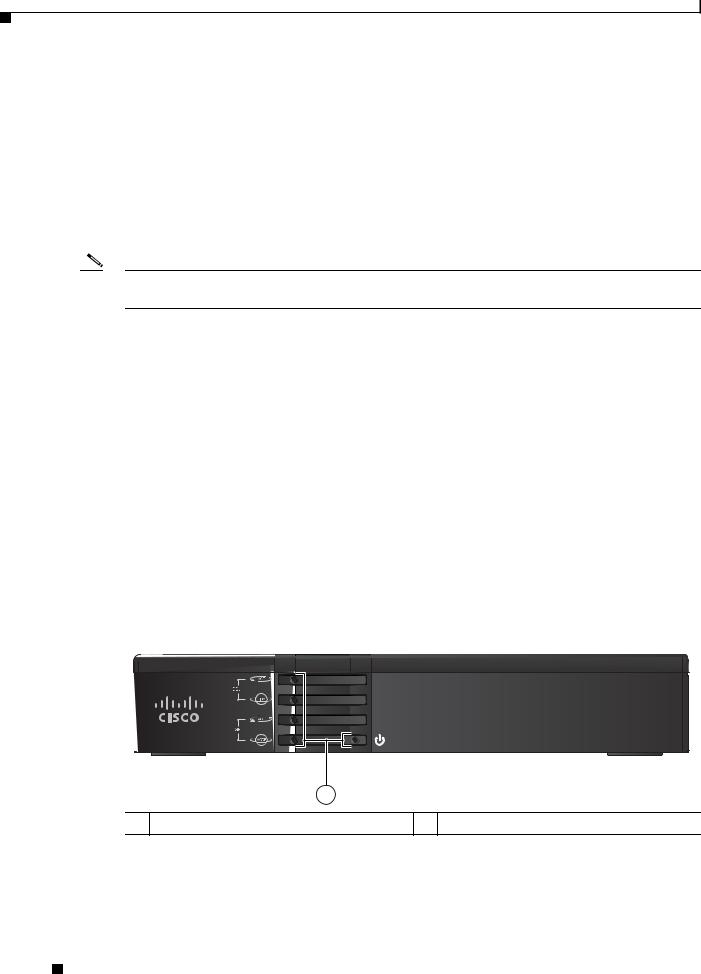
Figure 1-8 shows the front panel details of the Cisco 880 wireless data router. The USB port and the 3G card slot are located on the front panel.
|
|
Cisco 860 Series, Cisco 880 Series, and Cisco 890 Series Integrated Services Routers Hardware Installation Guide |
|
|
|
|
|
|
|||
|
OL-16215-11 |
|
|
1-11 |
|
|
|
|
|
||
Chapter 1 Product Overview
Cisco 880 Series ISRs
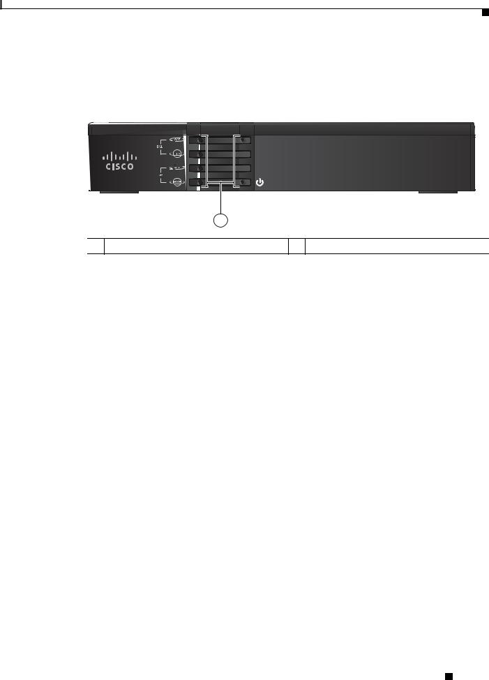
Figure 1-8 Front Panel of the Cisco 880 Series Wireless Data Router
 231950
1 |
2 |
3 |
1 LEDs |
3 USB port |
|
23G express card slot—Supports third-party1
3G card (Cisco 880G models only)
1.See the Cisco 880 Series Integrated Services Routers data sheet for supported vendors.
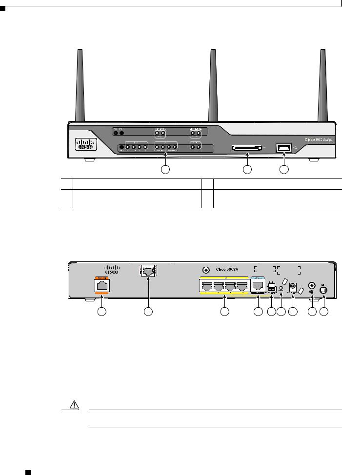
Figure 1-9 shows the back panel details of the Cisco 886VA data router.
Figure 1-9 Back Panel of the Cisco 886VA Router
|
|
|
|
|
|
|
|
254090 |
1 |
2 |
3 |
4 |
5 |
6 |
7 |
8 |
9 |
1 |
Data BRI1 0 |
6 |
Reset button |
2 |
Primary WAN port—VDSL/ADSL over |
7 |
Power connector |
|
ISDN |
|
|
|
|
|
|
3 |
4-port 10/100 Ethernet switch2 |
8 |
Earth ground connection |
4 |
Serial port—console or auxiliary |
9 |
Kensington security slot |
|
|
|
|
5 |
PoE power connector—optional |
|
|
|
|
|
|
1.BRI = Basic rate interface.
2.Ports 0 and 1 provide PoE with the optional PoE module installed.
Caution The primary WAN port is designed for an RJ-45 connector only. Damage to the primary WAN port may occur if a non-RJ-45 connector is inserted.
Cisco 860 Series, Cisco 880 Series, and Cisco 890 Series Integrated Services Routers Hardware Installation Guide
1-12 |
OL-16215-11 |
|
|

Chapter 1 Product Overview
Cisco 880 Series ISRs
Figure 1-10 shows the back panel details of the Cisco 887VA and 886VA-M data router.
Figure 1-10 Back Panel of the Cisco 887VA and 887VA-M Router
|
|
|
|
|
|
|
254139 |
1 |
2 |
3 |
4 |
5 |
6 |
7 |
8 |
1 |
Primary WAN port—VDSL/ADSL over |
5 |
Reset button |
|
POTS1 |
|
|
2 |
4-port 10/100 Ethernet switch2 |
6 |
Power connector |
3 |
Serial port—console or auxiliary |
7 |
Earth ground connection |
|
|
|
|
4 |
PoE power connector—optional |
8 |
Kensington security slot |
|
|
|
|
1.887VA-M has Annex M support.
2.Ports 0 and 1 provide PoE with the optional PoE module installed.
Caution For the Cisco 887VA, the primary WAN port is designed for an RJ-11 connector only. Damage to the primary WAN port may occur if a non-RJ-11 connector is inserted.
Figure 1-11 shows the back panel details of the Cisco 888W data router. Nonwireless routers do not have antennas on the back panel. However, the feature locations are similar across all Cisco 880 series data routers.
Figure 1-11 Back Panel of the Cisco 888W Data Router
|
|
|
|
|
|
|
|
|
231951 |
1 |
2 |
3 |
4 |
5 |
6 |
7 |
8 |
9 |
10 |
Cisco 860 Series, Cisco 880 Series, and Cisco 890 Series Integrated Services Routers Hardware Installation Guide
|
OL-16215-11 |
1-13 |
|
|
|

Chapter 1 Product Overview
Cisco 880 Series ISRs
1 |
ISDN port—not available on 3G models |
6 |
PoE power connector for optional PoE |
|
|
|
module1 |
2 |
Primary WAN port2—G.SHDSL, |
7 |
Reset button |
|
VDSLoPOTS, ADSLoPOTS, ADSLoISDN, |
|
|
|
or 10/100 FE |
|
|
|
|
|
|
3 |
Antenna—captive omnidirectional dipole |
8 |
Power connector |
|
WLAN antenna (wireless models only) |
|
|
|
|
|
|
4 |
4-port 10/100 Ethernet switch |
9 |
Earth ground connection |
|
|
|
|
5 |
Serial port—console or auxiliary |
10 |
Kensington security slot |
|
|
|
|
1.The Cisco 880 series ISRs can include an optional PoE module that provides power to 802.3af-compliant devices connected to ethernet ports 0 and 1. If this feature was not configured with the factory order, you must order and install it to enable the PoE function.
2.Depending on the router model, the primary WAN port can be G.SHDSL, VDSLoPOTS, or 10/100 FE. The VDSLoPOTS port is in the same location as the G.SHDSL port. The 10/100 FE WAN port is located at the bottom left corner. See Figure 1-2 for the location of the 10/100 FE WAN port.
Cisco 880 Series Voice and Data Routers
The Cisco 880 series voice and data routers provide both voice and data ports. The voice ports managed voice services that interface with Foreign Exchange Station (FXS), Foreign Exchange Office (FXO), or BRI connections.
Cisco 881 SRST and Cisco 888 SRST
Figure 1-12, Figure 1-13, and Figure 1-14 show the features available on the Cisco 881 SRST and Cisco 888 SRST routers. The features available vary, depending on the router model. Some features may not be available on your router.
Depending on the router model, the primary WAN port can be either G.SHDSL or 10/100 FE. See the Cisco 880 Series Integrated Services Routers data sheet for the WAN interface and voice ports that are supported on your router.
|
Cisco 860 Series, Cisco 880 Series, and Cisco 890 Series Integrated Services Routers Hardware Installation Guide |
1-14 |
OL-16215-11 |
Loading...