


 Loading...
GETTING STARTED GUIDE
Cisco Catalyst 9130AX Series Access
Points
First Published: October 25, 2019
Last Updated: February 06, 2020
Cisco Systems, Inc. www.cisco.com
1

Cisco Catalyst 9130AX Series Access Points
1About this Guide
2About the Cisco Catalyst 9130AX Series Wireless Access Point
3Safety Instructions
4Unpacking
5AP Views, Ports, and Connectors
6Preparing the AP for Installation
7Installation Overview
8Performing a Pre-Installation Configuration
9Mounting the Access Point
10Grounding the Access Point
11Powering the Access Point
12Configuring and Deploying the Access Point
13Self-Identifying Antennas
14Checking the Access Point LEDs
15Miscellaneous Usage and Configuration Guidelines
16FAQs
17Related Documentation
18Declarations of Conformity and Regulatory Information Communications, Services, and Additional Information Cisco Bug Search Tool
2

Cisco Catalyst 9130AX Series Access Points
1 About this Guide
This guide provides instructions on how to install your Cisco Catalyst 9130AX series access point and provides links to resources that can help you configure it. This guide also provides mounting instructions and troubleshooting information.
Note that the C9130AX series access point is referred to as the access point or the AP in this document.
2 About the Cisco Catalyst 9130AX Series Wireless Access Point
The Cisco Catalyst 9130AX series wireless access point is a dual-band, dual-concurrent, enterprise 802.11ax (Wi-Fi 6) AP. This AP series has two models, one with integrated antennas and the other with external antennas, which are designed to use both 2.4 GHz and the 5 GHz bands. This AP series supports a greater overall High Density Experience (HDX), which provides a more predictable performance for advanced applications such as 4K or 8K videos, high-density and high-definition collaboration applications, all-wireless offices, and Internet-of-Things (IoT). The AP supports full interoperability with leading 802.11ax and 802.11ac clients, along with a mixed deployment with other APs and controllers. These APs provide integrated security, resiliency and operational flexibility as well as increased network intelligence.
A full listing of the AP's features and specifications are provided in the Cisco Catalyst 9130AX Series Access Point Data Sheet, at the following URL: https://www.cisco.com/c/en/us/products/collateral/wireless/catalyst-9100ax-access-points/nb-06-cat-9130-ser-ap -ds-cte-en.html
Cisco Catalyst 9130AX Series Wireless Access Point Features
The C9130AX series AP is a wireless controller-based product, and supports:
Four radios, a dual-band 5 GHz (8x8) flexible radio with 2.4 GHz and 4x4 5 GHz, a single-band 5 GHz radio, and an omni IoT radio that can be used with BLE, Zigbee, Thread and other multi-protocol 802.15.4 devices
Four dual-band and four single-band 5 GHz integrated antennas on the C9130AXI AP models (C9130AXI-x and C9130AXI-EWC-x).
Note The ‘x’ in the model numbers represents the regulatory domain. For information on supported regulatory domains, see the“AP Model Numbers and Regulatory Domains” section on page 5.
Integrated internal antennas that are omni directional in azimuth, for both 2.4 GHz and 5 GHz bands.
External antennas on the C9130AXE AP model (C9130AXE-x and C9130AXE-EWC-x).
Multiuser Multiple-Input Multiple-Output (MU-MIMO) technology for uplink and downlink.
Orthogonal Frequency Division Multiple Access (OFDMA)-based scheduling for both uplink and downlink.
Multigigabit Ethernet (mGig)
The following hardware external interfaces:
—1x100/1000/2500/5000 Multigigabit Ethernet (RJ-45)
—RS-232 Console Interface through RJ-45
—Recovery push button (enables partial or full system configuration recovery)
—USB 2.0 Port
3

Cisco Catalyst 9130AX Series Access Points
—One multi-color LED Status indicator. see the “Self-Identifying Antennas” section on page 29 for information on the colors of the LED status indicator.
Integrated Bluetooth Low Energy (BLE) radio to enable IoT use cases such as location tracking and wayfinding.
Cisco RF ASIC, a fully integrated Software Defined Radio (SDR), that can perform advanced RF spectrum analysis and delivers features like CleanAir, Wireless Intrusion Prevention System (WIPS), and DFS detection.
Intelligent Capture probes the network and provides Cisco DNA Center with deep analysis.
Spatial Reuse (also known as Basic Service Set (BSS) coloring) which allows APs and their clients to differentiate between BSSs, thus permitting more simultaneous transmissions.
New power savings mode called Target Wake Time (TWT) which allows the client to stay asleep and wake up only at pre-scheduled (target) times to exchange data with the AP. This provides significant energy savings for battery-operated devices.
Cisco Digital Network Architecture (DNA) support enables Cisco DNA Spaces, Apple FastLane and Cisco Identity Services Engine.
Optimized AP Roaming for ensuring that client devices associate with the AP in their coverage range that offers the fastest data rate available.
Cisco CleanAir technology enhanced with 160MHz channel support. CleanAir delivers proactive, high-speed spectrum intelligence across 20-, 40-, and 80-, and 160-MHz-wide channels to combat performance problems arising from wireless interference.
The AP supports both Cisco Embedded Wireless Controller and lightweight deployments (using Cisco Wireless Controllers). The AP also supports the following operating modes:
Local—This is the default mode for the Cisco AP. In this mode, the AP serves clients.
In local mode, the AP creates two CAPWAP tunnels to the Cisco WLC, one for management and the other for data traffic. This is known as central switching because the data traffic is switched (bridged) from the AP to the controller where it is then routed.
FlexConnect—In FlexConnect mode (previously known as HREAP), the data traffic is switched locally and is not sent to the controller. In this mode, the Cisco AP behaves like an autonomous AP, but is managed by the Cisco WLC. Here, the AP continues to function even if connection to the controller is lost.
Monitor—In the monitor mode, specified Cisco APs can exclude themselves from handling data traffic between clients and the infrastructure. These APs act as dedicated sensors for location based services (LBS), rogue AP detection, and intrusion detection (IDS).
When APs are in monitor mode, they actively monitor the airwaves and typically do not serve clients.
Sniffer—In the wireless sniffer mode, the AP starts sniffing the air on a given channel. It captures and forwards all the packets from the clients on that channel to a remote machine that runs Airopeek or Wireshark (packet analyzers for IEEE 802.11 wireless LANs). This includes information on the time stamp, signal strength, packet size, etc.
Note In the sniffer mode, the server to which the data is sent should be on the same VLAN as the wireless controller management VLAN otherwise an error will be displayed.
4

Cisco Catalyst 9130AX Series Access Points
AP Model Numbers and Regulatory Domains
AP Type |
Model Number |
Details |
|
|
|
|
|
Access Point for indoor |
C9130AXI-x |
Dual-band, controller-based 802.11ax |
|
environments, with internal |
|
|
|
C9130AXI-EWC-x |
C9130AXI-x with a Cisco Embedded |
||
antennas |
|||
|
Wireless Controller software image |
||
|
|
||
|
|
|
|
Access Point for indoor |
C9130AXE-x |
Dual-band, controller-based 802.11ax |
|
environments, with external |
|
|
|
C9130AXE-EWC-x |
C9130AXE-x with a Cisco Embedded |
||
antennas |
|||
|
Wireless Controller software image |
||
|
|
||
|
|
|
You need to verify whether the AP model you have is approved for use in your country. To verify approval and to identify the regulatory domain that corresponds to a particular country, visit http://www.cisco.com/go/aironet/compliance. Not all regulatory domains have been approved. As and when they are approved, this compliance list will be updated.
Antennas and Radios
The C9130AX series access point configurations are:
C9130AXI-x
C9130AXI-EWC-x
C9130AXE-x
C9130AXE-EWC-x
Internal Antennas
The C9130AXI models (C9130AXI-x and C9130AXI-EWC-x) have four internal dual-band antennas with a dedicated 2.4 GHz radio and a 5 GHz radio, four internal single-band antennas with a dedicated 5 GHz radio, one internal single-band antenna with a dedicated 2.4 GHz IOT radio, and one dual-band antenna with a dedicated 2.4 GHz radio and a 5 GHz AUX radio.
External Antennas
The C9130AXE models (C9130AXE-x and C9130AXE-EWC-x) support up to eight external antennas. These include four dual-band and four single-band 5 GHz antennas.
The C9130AXE model has an 8-port Smart Antenna (DART) connector on its side. Ext 8*8 antennas can be directly connected to the C9130AXE AP using the 8-port Smart Antenna (DART) connector. Antennas with RP-TNC and N-type connectors can be connected to this 8-port DART cable connector using the AIR-CAB002-D8-R= for RP-TNC connectors or AIR-CAB003-D8-N= for N-type connectors.
For more information on Self Identifying Antennas, see “What are Self Identifying Antennas?” section on page 33
Note Always connect the antennas to the AP before powering the AP up. Enabling the AP radios without connecting the antennas can result in damage to the AP.
5

Cisco Catalyst 9130AX Series Access Points
The radio and antennas support frequency bands 2400–2500 MHz and 5150–5850 MHz through a common dual-band RF interface. The C-ANT9101=, C-ANT9102=, and C-ANT9103= support frequency bands 2400–2500 MHz and 5150–7125 MHz.
Table 1 |
List of External Antennas Supported on C9130AXE |
|
|
|||||
Part Number |
|
Description |
|
Gain |
||||
|
|
|
|
|||||
C-ANT9101= |
Ceiling Mount Omni Self-Identifying Antenna with |
|
2 dBi (2.4 GHz) |
|||||
|
|
|
Bluetooth, 8-port, with DART connectors. |
|
6 dBi (5 GHz) |
|||
|
|
|
|
|
|
|
|
3 dBi (BLE) |
|
|
|
|
|
||||
C-ANT9102= |
|
Pole or Wall Mount Omni Self-Identifying Antenna |
|
4 dBi (2.4 GHz) |
||||
|
|
|
with Bluetooth, 8-port, with DART connectors. |
|
4 dBi (5 GHz) |
|||
|
|
|
|
|
|
|
|
4 dBi (BLE) |
|
|
|
|
|
||||
C-ANT9103= |
|
Pole or Wall mount 75° Directional Self-Identifying |
|
6 dBi (2.4 GHz) |
||||
|
|
|
Antenna with Bluetooth, 8-port, with DART |
|
6 dBi (5 GHz) |
|||
|
|
|
connectors. |
|
6 dBi (BLE) |
|||
|
|
|
|
|||||
AIR-ANT2513P4M-N= |
Patch Antenna, 4-port, with N connectors. |
|
13 dBi (2.4 GHz) |
|||||
|
|
|
|
|
|
|
|
13 dBi (5 GHz) |
|
|
|
|
|
|
|
|
13 dBi (BLE) |
|
|
|
|
|
|
|
|
|
|
|
|
Note Connect to AP using AIR-CAB003-D8-N=. |
|
|
|||
|
|
|
|
|
|
|||
|
|
|
|
|||||
AIR-ANT2524V4C-R= |
Ceiling Mount Omni Antenna, 4-port, with RP-TNC |
|
2 dBi (2.4 GHz) |
|||||
|
|
|
connectors. |
|
4 dBi (5 GHz) |
|||
|
|
|
|
|
|
|
|
|
|
|
|
Note Connect to AP using AIR-CAB002-D8-R=. |
|
|
|||
|
|
|
|
|
||||
|
|
|
|
|||||
AIR-ANT2524V4C-RS= |
Ceiling Mount Omni Self-Identifying Antenna, 4-port, |
|
2 dBi (2.4 GHz) |
|||||
|
|
|
with RP-TNC connectors. |
|
4 dBi (5 GHz) |
|||
|
|
|
|
|
|
|
|
|
|
|
|
Note Connect to AP using AIR-CAB002-D8-R=. |
|
|
|||
|
|
|
|
|
||||
|
|
|
|
|||||
AIR-ANT2544V4M-R= |
Wall Mount Omni Antenna, 4-port, with RP-TNC |
|
4 dBi (2.4 GHz) |
|||||
|
|
|
connectors. |
|
4 dBi (5 GHz) |
|||
|
|
|
|
|
|
|
|
|
|
|
|
Note Connect to AP using AIR-CAB002-D8-R=. |
|
|
|||
|
|
|
|
|
||||
|
|
|
|
|||||
AIR-ANT2544V4M-RS= |
Wall Mount Omni Self-Identifying Antenna, 4-port, |
|
4 dBi (2.4 GHz) |
|||||
|
|
|
with RP-TNC connectors. |
|
4 dBi (5 GHz) |
|||
|
|
|
|
|
|
|
|
|
|
|
|
Note Connect to AP using AIR-CAB002-D8-R=. |
|
|
|||
|
|
|
|
|
||||
|
|
|
|
|||||
AIR-ANT2566D4M-R= |
60° Patch Antenna, 4-port, with RP-TNC connectors. |
|
6 dBi (2.4 GHz) |
|||||
|
|
|
|
|
|
|
|
6 dBi (5 GHz) |
|
|
|
|
|
|
|
|
|
|
|
|
Note Connect to AP using AIR-CAB002-D8-R=. |
|
|
|||
|
|
|
|
|
||||
|
|
|
|
|||||
AIR-ANT2566D4M-RS= |
60° Patch Self-Identifying Antenna, 4-port, with |
|
6 dBi (2.4 GHz) |
|||||
|
|
|
RP-TNC connectors. |
|
6 dBi (5 GHz) |
|||
|
|
|
|
|
|
|
|
|
|
|
|
Note Connect to AP using AIR-CAB002-D8-R=. |
|
|
|||
|
|
|
|
|
|
|
|
|
|
|
|
|
|
|
|
|
|
6

Cisco Catalyst 9130AX Series Access Points
Table 1 |
List of External Antennas Supported on C9130AXE |
|
|
||||
Part Number |
|
Description |
|
Gain |
|||
|
|
|
|
||||
AIR-ANT2566P4W-R= |
Directional Antenna, 4-port, with RP-TNC |
|
6 dBi (2.4 GHz) |
||||
|
|
|
connectors. |
|
6 dBi (5 GHz) |
||
|
|
|
|
|
|
|
|
|
|
|
Note Connect to AP using AIR-CAB002-D8-R=. |
|
|
||
|
|
|
|
|
|||
|
|
|
|
||||
AIR-ANT2566P4W-RS= |
Directional Self-Identifying Antenna, 4-port, with |
|
6 dBi (2.4 GHz) |
||||
|
|
|
RP-TNC connectors. |
|
6 dBi (5 GHz) |
||
|
|
|
|
|
|
|
|
|
|
|
Note Connect to AP using AIR-CAB002-D8-R=. |
|
|
||
|
|
|
|
|
|
|
|
|
|
|
|
|
|
|
|
Note When using the breakout cables and connecting to legacy dual band antennas, the BLE radio will experience the gain of that antenna at 2.4 GHz.
Cisco also provides the following external antenna accessories:
2 ft Smart Antenna Connector to RP-TNC breakout cable (AIR-CAB002-D8-R=)—For conventional (non-DART) antennas with gains up to 6 dBi
3 ft Smart Antenna Connector to N Connectors (AIR-CAB003-D8-N=)—For conventional (non-DART) antennas with gains up to 13 dBi
Antenna bracket (AIR-AP-BRACKET-9=)—To mount the C9130AXE directly to the back of the C-ANT9103= antenna
3 Safety Instructions
Translated versions of the following safety warnings are provided in the translated safety warnings document that is shipped with your access point. The translated warnings are also in the Translated Safety Warnings for Cisco Catalyst Access Points, which is available on Cisco.com.
Warning |
IMPORTANT SAFETY INSTRUCTIONS |
||
|
|
This warning symbol means danger. You are in a situation that could cause bodily injury. Before you |
|
|
|
work on any equipment, be aware of the hazards involved with electrical circuitry and be familiar with |
|
|
|
standard practices for preventing accidents. Use the statement number provided at the end of each |
|
|
|
warning to locate its translation in the translated safety warnings that accompanied this device. |
|
|
|
SAVE THESE INSTRUCTIONS Statement 1071 |
|
|
|
|
|
|
|
|
|
Warning |
Read the installation instructions before using, installing or connecting the system to the power source. |
||
|
|
Statement 1004 |
|
|
|
|
|
7

Cisco Catalyst 9130AX Series Access Points
Warning
Warning
Warning
Warning
Warning
This product relies on the building’s installation for short-circuit (overcurrent) protection. Ensure that the protective device is rated not greater than 20A. Statement 1005
Installation of the equipment must comply with local and national electrical codes. Statement 1074
In order to comply with FCC radio frequency (RF) exposure limits, antennas should be located at a minimum of 12 inches (30 cm) or more from the body of all persons. Statement 332
Ultimate disposal of this product should be handled according to all national laws and regulations.
Statement 1040
This equipment is suitable for use in environment air spaces (plenums) in accordance with Section 300.22 (C) of the National Electrical Code, and Sections 2-128, 12-010(3) and 12-100 of the Canadian Electrical Code, Part 1, CSA C22.2. External power supply, power adapter and/or power injector, if provided, are not suitable for installation in air spaces. Statement 440
4 Unpacking
To unpack the access point, follow these steps:
Step 1 Unpack and remove the access point and the accessory kit from the shipping box.
Step 2 Return any packing material to the shipping container and save it for future use.
Step 3 Verify that you have received the items listed below. If any item is missing or damaged, contact your Cisco representative or reseller for instructions.
—The access point
—(Optional) Mounting bracket (AIR-AP-BRACKET-1= (default) or AIR-AP-BRACKET-2=, only if selected when you order the access point)
—Adjustable ceiling-rail clip (AIR-AP-T-RAIL-R or AIR-AP-T-RAIL-F) (selected when you order the access point)
The following accessories can be ordered separately from Cisco:
•Antenna bracket AIR-AP-BRACKET-9= to mount the C9130AXE directly to the back of the C-ANT9103= antenna
•AIR-AP-BRACKET-1= for ceiling mount installations
•AIR-AP-BRACKET-2= for wall or electrical box installations
•Mid-span power injector AIR-PWRINJ6= when PoE is not available
8

Cisco Catalyst 9130AX Series Access Points
5 AP Views, Ports, and Connectors
Figure 1 Face of the 9130AXI Model
1 |
Status LED |
3 |
USB 2.0 port |
|
|
|
|
2 |
Location of the ports and connectors on the head of the |
|
|
AP. |
|
|
|
|
|
|
|
9
Cisco Catalyst 9130AX Series Access Points
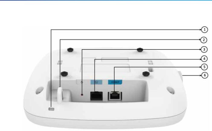
Figure 2 Ports and Connectors on the Head of the C9130AXI Model
1 |
Kensington lock slot |
4 |
RJ-45 console port |
|
|
|
|
2 |
Security hasp for padlocking AP to mounting bracket |
5 |
5 GbE port |
|
|
|
|
|
Mode button |
|
USB 2.0 port |
3 |
For information on how to use the Mode button, see “Using |
6 |
|
the Mode Button” section. |
|
||
|
|
|
|
10
Cisco Catalyst 9130AX Series Access Points
Figure 3 Face of the C9130AXE Model
1 |
Location of the Smart Antenna connector port under yellow cap1 |
3 |
Status LED |
2 |
Location of the ports on the head of the AP. |
4 |
USB 2.0 port |
|
|
|
|
1. Only external antennas with the 8-port DART cable can be connected to this AP.
11
Cisco Catalyst 9130AX Series Access Points
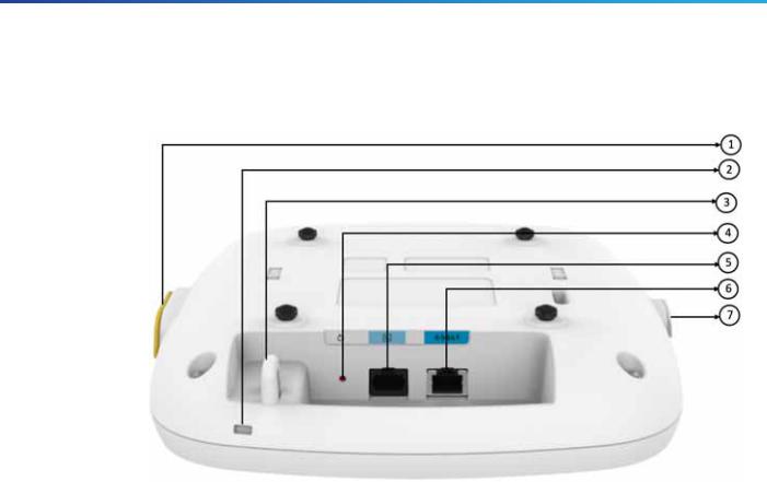
The ports and connections on the bottom of the access point are shown in Figure 4.
Figure 4 Ports and Connections on the Head of the C9130AXE Model
|
8-port Smart Antenna (DART) connector |
4 |
Mode button |
|
1 |
port, under a yellow cap1 |
|
For more information, see “Using the Mode Button” section. |
|
For more information, see “What is a |
|
|
||
5 |
RJ-45 console port |
|||
|
Smart Antenna connector?” section. |
|||
|
|
|||
|
|
|
|
|
2 |
Kensington lock slot |
6 |
5 GbE port |
|
|
|
|
|
|
3 |
Security hasp for padlocking AP to |
|
USB 2.0 port |
|
|
mounting bracket |
7 |
|
|
|
|
|
|
1. Only external antennas with the 8-port DART cable can be connected to this AP.
12

Cisco Catalyst 9130AX Series Access Points
dC9130AXI (Internal Antenna)
The C9130AXI access point is equipped with four integrated, omnidirectional, dual-band antennas (2.4 GHz and 5 GHz), four integrated, omnidirectional, single-band antennas (5 GHz only), one integrated, omnidirectional, single-band antenna (2.4 GHz) for the dedicated 2.4 GHz IOT radio, and one integrated, omnidirectional, dual-band antenna (2.4 GHz and 5 GHz) for the dedicated 2.4 GHz and 5 GHz AUX radio.
Figure 3-5 C9130AXI - Dual-band Antenna radiation pattern (2.4 GHz Azimuth)
13

Cisco Catalyst 9130AX Series Access Points
Figure 3-6 C9130AXI - Dual-band Antenna radiation pattern (2.4 GHz Elevation)
14

Cisco Catalyst 9130AX Series Access Points
Figure 3-7 C9130AXI - Dual-band Antenna radiation pattern (5 GHz Azimuth)
15
Loading...