


 Loading...
Catalyst 3850 Switch Hardware Installation Guide
First Published: 2013-01-21
Last Modified: 2015-09-22
Americas Headquarters
Cisco Systems, Inc. 170 West Tasman Drive
San Jose, CA 95134-1706 USA http://www.cisco.com Tel: 408 526-4000
800 553-NETS (6387) Fax: 408 527-0883
Text Part Number: OL-26779-05
THE SPECIFICATIONS AND INFORMATION REGARDING THE PRODUCTS IN THIS MANUAL ARE SUBJECT TO CHANGE WITHOUT NOTICE. ALL STATEMENTS, INFORMATION, AND RECOMMENDATIONS IN THIS MANUAL ARE BELIEVED TO BE ACCURATE BUT ARE PRESENTED WITHOUT WARRANTY OF ANY KIND, EXPRESS OR IMPLIED. USERS MUST TAKE FULL RESPONSIBILITY FOR THEIR APPLICATION OF ANY PRODUCTS.
THE SOFTWARE LICENSE AND LIMITED WARRANTY FOR THE ACCOMPANYING PRODUCT ARE SET FORTH IN THE INFORMATION PACKET THAT SHIPPED WITH THE PRODUCT AND ARE INCORPORATED HEREIN BY THIS REFERENCE. IF YOU ARE UNABLE TO LOCATE THE SOFTWARE LICENSE OR LIMITED WARRANTY, CONTACT YOUR CISCO REPRESENTATIVE FOR A COPY.
The following information is for FCC compliance of Class A devices: This equipment has been tested and found to comply with the limits for a Class A digital device, pursuant to part 15 of the FCC rules. These limits are designed to provide reasonable protection against harmful interference when the equipment is operated in a commercial environment. This equipment generates, uses, and can radiate radio-frequency energy and, if not installed and used in accordance with the instruction manual, may cause harmful interference to radio communications. Operation of this equipment in a residential area is likely to cause harmful interference, in which case users will be required to correct the interference at their own expense.
The following information is for FCC compliance of Class B devices: This equipment has been tested and found to comply with the limits for a Class B digital device, pursuant to part 15 of the FCC rules. These limits are designed to provide reasonable protection against harmful interference in a residential installation. This equipment generates, uses and can radiate radio frequency energy and, if not installed and used in accordance with the instructions, may cause harmful interference to radio communications. However, there is no guarantee that interference will not occur in a particular installation. If the equipment causes interference to radio or television reception, which can be determined by turning the equipment off and on, users are encouraged to try to correct the interference by using one or more of the following measures:
•
•
•
•
Reorient or relocate the receiving antenna.
Increase the separation between the equipment and receiver.
Connect the equipment into an outlet on a circuit different from that to which the receiver is connected.
Consult the dealer or an experienced radio/TV technician for help.
Modifications to this product not authorized by Cisco could void the FCC approval and negate your authority to operate the product
The Cisco implementation of TCP header compression is an adaptation of a program developed by the University of California, Berkeley (UCB) as part of UCB’s public domain version of the UNIX operating system. All rights reserved. Copyright © 1981, Regents of the University of California.
NOTWITHSTANDING ANY OTHER WARRANTY HEREIN, ALL DOCUMENT FILES AND SOFTWARE OF THESE SUPPLIERS ARE PROVIDED "AS IS" WITH ALL FAULTS. CISCO AND THE ABOVE-NAMED SUPPLIERS DISCLAIM ALL WARRANTIES, EXPRESSED OR IMPLIED, INCLUDING, WITHOUT LIMITATION, THOSE OF MERCHANTABILITY, FITNESS FOR A PARTICULAR PURPOSE AND NONINFRINGEMENT OR ARISING FROM A COURSE OF DEALING, USAGE, OR TRADE PRACTICE.
IN NO EVENT SHALL CISCO OR ITS SUPPLIERS BE LIABLE FOR ANY INDIRECT, SPECIAL, CONSEQUENTIAL, OR INCIDENTAL DAMAGES, INCLUDING, WITHOUT LIMITATION, LOST PROFITS OR LOSS OR DAMAGE TO DATA ARISING OUT OF THE USE OR INABILITY TO USE THIS MANUAL, EVEN IF CISCO OR ITS SUPPLIERS HAVE BEEN ADVISED OF THE POSSIBILITY OF SUCH DAMAGES.
Any Internet Protocol (IP) addresses and phone numbers used in this document are not intended to be actual addresses and phone numbers. Any examples, command display output, network topology diagrams, and other figures included in the document are shown for illustrative purposes only. Any use of actual IP addresses or phone numbers in illustrative content is unintentional and coincidental.
Cisco and the Cisco logo are trademarks or registered trademarks of Cisco and/or its affiliates in the U.S. and other countries. To view a list of Cisco trademarks, go to this URL: http:// www.cisco.com/go/trademarks. Third-party trademarks mentioned are the property of their respective owners. The use of the word partner does not imply a partnership relationship between Cisco and any other company. (1110R)
© 2016 Cisco Systems, Inc. All rights reserved.

P r e f a c e
C H A P T E R 1
C O N T E N T S
Preface ix
Document Conventions ix
Related Documentation xi
Obtaining Documentation and Submitting a Service Request xi
Product Overview 1
Switch Models 1
Front Panel 5
10/100/1000 Ports 7
PoE, PoE+, and Cisco UPoE Ports 7
SFP and QSFP Module Slots 8
Management Ports 8
USB Type A Port 9
Network Modules 10
SFP and SFP+ Modules 12
LEDs 12
SYST LED 15
XPS LED 16
Port LEDs and Modes 16
USB Console LED 19
S-PWR LED 20
ACTV LED 20
STACK LED 20
PoE LED 21
UID/Beacon LED 21
Network Module LEDs 22
Rear Panel 23
Catalyst 3850 Switch Hardware Installation Guide
OL-26779-05 |
iii |

Contents
C H A P T E R 2
RJ-45 Console Port LED 26
StackWise Ports 26
Power Supply Modules 26
Fan Module 29
StackPower Connector 31
Ethernet Management Port 31
RJ-45 Console Port 32
Management Options 32
Switch Installation 33
Preparing for Installation 33
Safety Warnings 33
Installation Guidelines 35
Box Contents 36
Tools and Equipment 36
Verifying Switch Operation 36
Powering Off the Switch 36
Planning a Switch Data Stack 36
Switch Stacking and Power Stacking Guidelines 37
Data Stack Cabling Configurations 38
Data Stack Bandwidth and Partitioning Examples 39
Power-On Sequence for Switch Stacks 40
Planning a StackPower Stack 41
StackPower Stacking Guidelines 41
StackPower Cabling Configurations 42
StackPower Partitioning Examples 43
Installing the Switch 44
Rack-Mounting 44
Attaching the Rack-Mount Brackets 46
Mounting the Switch a Rack 47
Installing the Switch on a Table or Shelf 48
After Switch Installation 48
Connecting to the StackWise Ports 48
Connecting to the StackPower Ports 49
Installing a Network Module in the Switch 50
Catalyst 3850 Switch Hardware Installation Guide
iv |
OL-26779-05 |

Contents
Installing and Removing SFP, SFP+ and QSFP+ Modules 50
Connecting Devices to the Ethernet Ports 50
10/100/1000 Port Connections 50
Auto-MDIX Connections 50
PoE+ and Cisco UPOE Port Connections 51
Where to Go Next 52
C H A P T E R 3
C H A P T E R 4
Installing a Network Module 53
Network Module Overview 53
Network Module LEDs 57
Installing a Network Module in the Switch 58
Safety Warnings 58
Equipment That You Need 59
Installing Network Modules 59
Network Module Port Configurations 61
C3850-NM-4-1G Module 61
C3850-NM-4-10G Module 61
C3850-NM-2-10G Module 62
C3850-NM-8-10G Module 63
C3850-NM-2-40G Module 63
Removing a Network Module 64
SFP and SFP+ Modules 65
Installing SFP and SFP+ Modules 65
Removing SFP and SFP+ Modules 67
Finding the Network Module Serial Number 67
Power Supply Installation 69
Power Supply Module Overview 69
Installation Guidelines 73
Installing or Replacing an AC Power Supply 74
Installing a DC Power Supply 76
Equipment That You Need 77
Grounding the Switch 77
Installing the DC Power Supply in the Switch 79
Wiring the DC Input Power Source 81
Catalyst 3850 Switch Hardware Installation Guide
OL-26779-05 |
v |

Contents
Finding the Power Supply Module Serial Number 82
C H A P T E R 5
C H A P T E R 6
A P P E N D I X A
A P P E N D I X B
Installing the Fan 83
Fan Module Overview 83
Installation Guidelines 84
Installing a Fan Module 85
Finding the Fan Module Serial Number 85
Troubleshooting 87
Diagnosing Problems 87
Switch POST Results 87
Switch LEDs 87
Switch Connections 87
Bad or Damaged Cable 87
Ethernet and Fiber-Optic Cables 88
Link Status 88
10/100/1000 Port Connections 88
10/100/1000 PoE+ Port Connections 88
SFP and SFP+ Module 89
Interface Settings 89
Ping End Device 90
Spanning Tree Loops 90
Switch Performance 90
Speed, Duplex, and Autonegotiation 90
Autonegotiation and Network Interface Cards 90
Cabling Distance 91
Clearing the Switch IP Address and Configuration 91
Replacing a Failed Data Stack Member 91
Technical Specifications 93
Environmental and Physical Specifications 93
Specifications for the Power Supplies, Switches, and Fan 95
Connector and Cable Specifications 101
Connector Specifications 101
Catalyst 3850 Switch Hardware Installation Guide
vi |
OL-26779-05 |

Contents
10/100/1000 Ports (Including PoE) 101
SFP Module Connectors 102
Console Port 103
Cables and Adapters 103
StackWise Cables 103
SFP Module Cables 104
Cable Pinouts 105
Console Port Adapter Pinouts 106
A P P E N D I X C
Configuring the Switch with the CLI-Based Setup Program 109 |
|
|
Accessing the CLI Through Express Setup 109 |
|
|
Accessing the CLI Through the Console Port 109 |
|
|
Connecting the RJ-45 Console Port |
110 |
|
Connecting the USB Console Port |
110 |
|
Installing the Cisco Microsoft Windows USB Device Driver |
114 |
|
Installing the Cisco Microsoft Windows XP USB Driver |
114 |
|
Installing the Cisco Microsoft Windows 2000 USB Driver 114
Installing the Cisco Microsoft Windows Vista and Windows 7 USB Driver 115
Uninstalling the Cisco Microsoft Windows USB Driver 115
Uninstalling the Cisco Microsoft Windows XP and 2000 USB Driver 115
Using the Setup.exe Program 115
Using the Add or Remove Programs Utility 116
Uninstalling the Cisco Microsoft Windows Vista and Windows 7 USB Driver 116
Entering the Initial Configuration Information 117
IP Settings 117
Completing the Setup Program 117
Catalyst 3850 Switch Hardware Installation Guide
OL-26779-05 |
vii |

Contents
Catalyst 3850 Switch Hardware Installation Guide
viii |
OL-26779-05 |

Preface
• Document Conventions, page ix
• Related Documentation, page xi
• Obtaining Documentation and Submitting a Service Request, page xi
Document Conventions
This document uses the following conventions:
Convention |
Description |
^ or Ctrl |
Both the ^ symbol and Ctrl represent the Control (Ctrl) key on a keyboard. For |
|
example, the key combination ^D or Ctrl-D means that you hold down the Control |
|
key while you press the D key. (Keys are indicated in capital letters but are not |
|
case sensitive.) |
bold font |
Commands and keywords and user-entered text appear in bold font. |
Italic font |
Document titles, new or emphasized terms, and arguments for which you supply |
|
values are in italic font. |
Courier font |
Terminal sessions and information the system displays appear in courier font. |
Bold Courier font |
Bold Courier font indicates text that the user must enter. |
[x] |
Elements in square brackets are optional. |
... |
An ellipsis (three consecutive nonbolded periods without spaces) after a syntax |
|
element indicates that the element can be repeated. |
| |
A vertical line, called a pipe, indicates a choice within a set of keywords or |
|
arguments. |
[x | y] |
Optional alternative keywords are grouped in brackets and separated by vertical |
|
bars. |
Catalyst 3850 Switch Hardware Installation Guide
OL-26779-05 |
ix |
Preface
Document Conventions
Convention |
Description |
{x | y} |
Required alternative keywords are grouped in braces and separated by vertical |
|
bars. |
[x {y | z}] |
Nested set of square brackets or braces indicate optional or required choices |
|
within optional or required elements. Braces and a vertical bar within square |
|
brackets indicate a required choice within an optional element. |
string |
A nonquoted set of characters. Do not use quotation marks around the string or |
|
the string will include the quotation marks. |
< > |
Nonprinting characters such as passwords are in angle brackets. |
[ ] |
Default responses to system prompts are in square brackets. |
!, # |
An exclamation point (!) or a pound sign (#) at the beginning of a line of code |
|
indicates a comment line. |
Reader Alert Conventions
This document may use the following conventions for reader alerts:
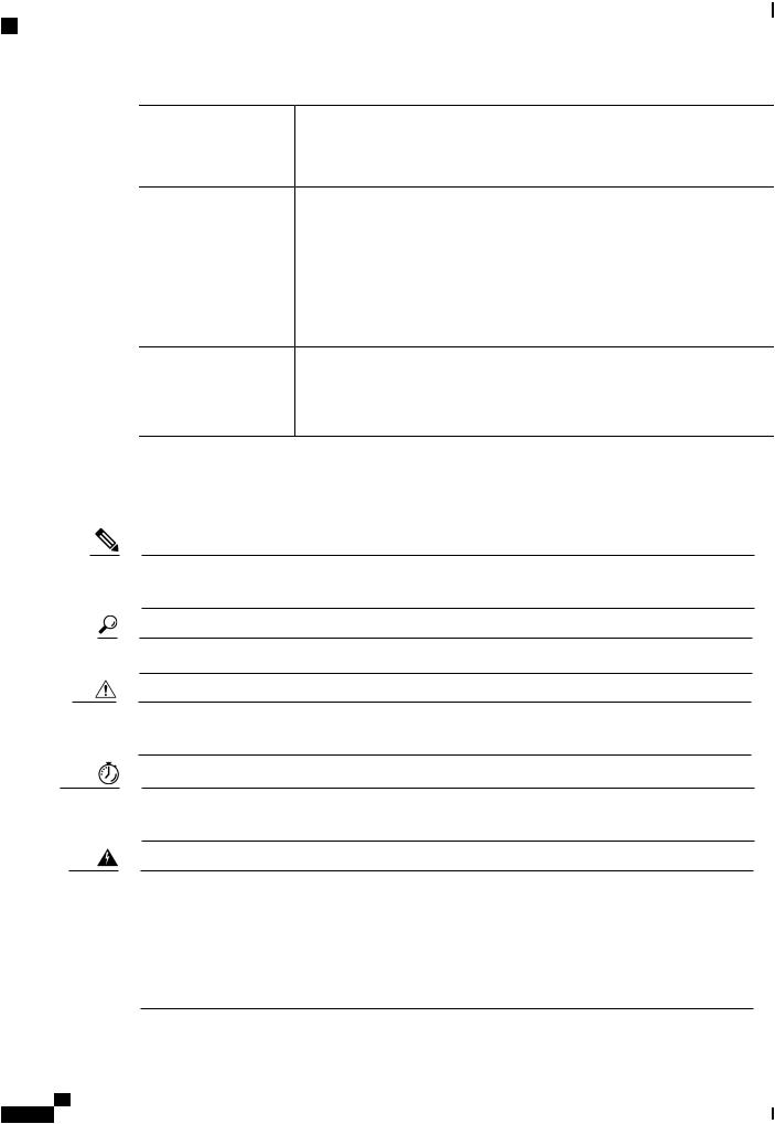
Note Means reader take note. Notes contain helpful suggestions or references to material not covered in the manual.
Tip Means the following information will help you solve a problem.
Caution Means reader be careful. In this situation, you might do something that could result in equipment damage or loss of data.
Timesaver Means the described action saves time. You can save time by performing the action described in the paragraph.
Warning IMPORTANT SAFETY INSTRUCTIONS
This warning symbol means danger. You are in a situation that could cause bodily injury. Before you work on any equipment, be aware of the hazards involved with electrical circuitry and be familiar with standard practices for preventing accidents. Use the statement number provided at the end of each warning to locate its translation in the translated safety warnings that accompanied this device. Statement 1071
SAVE THESE INSTRUCTIONS
Catalyst 3850 Switch Hardware Installation Guide
x |
OL-26779-05 |
Preface
Related Documentation
Related Documentation
Note Before installing or upgrading the switch, refer to the switch release notes.
•Cisco Catalyst 3850 Series Switches documentation, located at: http://www.cisco.com/go/cat3850_docs
•Cisco Catalyst 3650 Series Switchesdocumentation, located at: http://www.cisco.com/go/cat3650_docs
•Catalyst 2960-X Switch documentation, located at: http://www.cisco.com/go/cat2960x_docs
•Cisco SFP and SFP+ modules documentation, including compatibility matrixes, located at: http://www.cisco.com/en/US/products/hw/modules/ps5455/tsd_products_support_series_home.html
•Cisco SFP, SFP+, and QSFP+ modules documentation, including compatibility matrixes, located at: http://www.cisco.com/en/US/products/hw/modules/ps5455/tsd_products_support_series_home.html
•Cisco Validated Designs documents, located at: http://www.cisco.com/go/designzone
Obtaining Documentation and Submitting a Service Request
For information on obtaining documentation, submitting a service request, and gathering additional information, see the monthly What's New in Cisco Product Documentation, which also lists all new and revised Cisco technical documentation, at:
http://www.cisco.com/c/en/us/td/docs/general/whatsnew/whatsnew.html
Subscribe to the What's New in Cisco Product Documentation as a Really Simple Syndication (RSS) feed and set content to be delivered directly to your desktop using a reader application. The RSS feeds are a free service and Cisco currently supports RSS version 2.0.
Catalyst 3850 Switch Hardware Installation Guide
OL-26779-05 |
xi |

Preface
Obtaining Documentation and Submitting a Service Request
Catalyst 3850 Switch Hardware Installation Guide
xii |
OL-26779-05 |

C H A P T E R 1
Product Overview
The Catalyst 3850 family of switches are Ethernet switches to which you can connect devices such as Cisco IP Phones, Cisco Wireless Access Points, workstations, and other network devices such as servers, routers, and other switches.
TheCatalyst3850switchessupportstackingthroughCiscoStackWise-480technologyandpowermanagement through StackPower. The StackWise technology for the Catalyst 3850 switches is called StackWise-480.
Unless otherwise noted, the term switch refers to a standalone switch and to a switch stack.
This chapter contains these topics:
• Switch Models, page 1
• Front Panel, page 5
• Rear Panel, page 23
• Management Options, page 32
Switch Models
Table 1: Catalyst 3850 Switch Models and Descriptions
Switch Model |
Supported |
Description |
|
Software |
|
|
Image |
|
WS-C3850-24T-L |
LAN Base |
Stackable 24 10/100/1000 Ethernet ports, 1 network module |
|
|
slot1, 350 W power supply |
WS-C3850-48T-L |
LAN Base |
Stackable 48 10/100/1000 Ethernet ports, 1 network module |
|
|
slot, 350 W power supply |
WS-C3850-24P-L |
LAN Base |
Stackable 24 10/100/1000 PoE+2 ports, 1 network module |
|
|
slot, 715 W power supply |
Catalyst 3850 Switch Hardware Installation Guide
OL-26779-05 |
1 |

Product Overview
Switch Models
Switch Model |
Supported |
Description |
|
Software |
|
|
Image |
|
WS-C3850-48P-L |
LAN Base |
Stackable 48 10/100/1000 PoE+ ports, 1 network module |
|
|
slot, 715 W power supply |
WS-C3850-48F-L |
LAN Base |
Stackable 48 10/100/1000 PoE+ ports, 1 network module |
|
|
slot, 1100 W power supply |
WS-C3850-24U-L |
LAN Base |
Stackable 24 10/100/1000 Cisco UPOE3 ports, 1 network |
|
|
module slot, 1100 W power supply |
WS-C3850-48U-L |
LAN Base |
Stackable 48 10/100/1000 Cisco UPOE ports, 1 network |
|
|
module slot, 1100 W power supply |
WS-C3850-12X48U-L |
LAN Base |
Stackable 12 100M/1G/2.5G/5G/10G and 36 1G UPoE ports, |
|
|
1 network module slot, 1100 W power supply |
WS-C3850-24XU-L |
LAN Base |
Stackable 24 100M/1G/2.5G/5G/10G UPoE ports, 1 network |
|
|
module slot, 1100-W power supply |
WS-C3850-24T-S |
IP Base |
Stackable 24 10/100/1000 Ethernet ports, 1 network module |
|
|
slot, 350 W power supply |
WS-C3850-48T-S |
IP Base |
Stackable 48 10/100/1000 Ethernet ports, 1 network module |
|
|
slot, 350 W power supply |
WS-C3850-24P-S |
IP Base |
Stackable 24 10/100/1000 PoE+ ports, 1 network module |
|
|
slot, 715 W power supply |
WS-C3850-48P-S |
IP Base |
Stackable 48 10/100/1000 PoE+ ports, 1 network module |
|
|
slot, 715 W power supply |
WS-C3850-48F-S |
IP Base |
Stackable 48 10/100/1000 PoE+ ports, 1 network module |
|
|
slot, 1100 W power supply |
WS-C3850-24U-S |
IP Base |
Stackable 24 10/100/1000 Cisco UPOE ports, 1 network |
|
|
module slot, 1100 W power supply |
WS-C3850-48U-S |
IP Base |
Stackable 48 10/100/1000 Cisco UPOE ports, 1 network |
|
|
module slot, 1100 W power supply |
WS-C3850-24PW-S |
IP Base |
Catalyst 3850 24-port PoE IP Base with 5 access points |
|
|
license |
WS-C3850-48PW-S |
IP Base |
Catalyst 3850 48-port PoE IP Base with 5 access points |
|
|
license |
WS-C3850-12S-S |
IP Base |
Stackable 12 SFP module slots, 1 network module slot, 350 |
|
|
W power supply |
Catalyst 3850 Switch Hardware Installation Guide
2 |
OL-26779-05 |

Product Overview
Switch Models
Switch Model
WS-C3850-24S-S
WS-C3850-12XS-S
WS-C3850-16XS-S
WS-C3850-24XS-S
WS-C3850-32XS-S
WS-C3850-48XS-S
WS-C3850-48XS-F-S
WS-C3850-12X48U-S
WS-C3850-12X48UW-S
WS-C3850-24XU-S
WS-C3850-24XUW-S
WS-C3850-24T-E
OL-26779-05
Supported |
Description |
Software |
|
Image |
|
IP Base |
Stackable 24 SFP module slots, 1 network module slot, 350 |
|
W power supply |
IP Base |
Catalyst 3850 12-port SFP+ transceiver, 1 network module |
|
slot, support for up to 10 G SFP+, 350 W power supply |
IP Base |
Catalyst 3850 16-port SFP+ transceiver, 1 network module |
|
slot, support for up to 10 G SFP+, 350 W power supply. |
|
16 ports are available when the C3850-NM-4-10G network |
|
module is plugged into the WS-C3850-12XS-S switch. |
IP Base |
Catalyst 3850 24-port SFP+ transceiver, 1 network module |
|
slot, support for up to 10 G SFP+, 715 W power supply. |
IP Base |
Catalyst 3850 32-port SFP+ transceiver, 1 network module |
|
slot, support for up to 10 G SFP+, 715 W power supply. |
|
32 ports are available when the C3850-NM-8-10G network |
|
module is plugged into the WS-C3850-24XS-S switch. |
IP Base |
Catalyst 3850 switch with SFP+ transceivers, 48 ports that |
|
support up to 10 G, and 4 QSFP ports that support up to 40 |
|
G. 750 W power supply.4 |
|
The airflow direction for this switch is from the front panel |
|
to the rear panel. |
IP Base |
Catalyst 3850 switch with SFP+ transceivers, 48 ports that |
|
support up to 10 G, and 4 QSFP ports that support up to 40 |
|
G. 750 W power supply. |
|
The airflow direction for this switch is from the rear panel to |
|
the front panel. |
IP Base |
Stackable 12 100M/1G/2.5G/5G/10G and 36 1 G UPoE ports, |
|
1 network module slot, 1100 W power supply |
IP Base |
Stackable 12 100M/1G/2.5G/5G/10G and 36 1 G UPoE ports, |
|
1 network module slot, 1100 W power supply |
IP Base |
Stackable 24 100M/1G/2.5G/5G/10G UPoE ports, 1 network |
|
module slot, 1100-W power supply |
IP Base |
Stackable 24 100M/1G/2.5G/5G/10G UPoE ports, 1 network |
|
module slot, 1100-W power supply |
IP Services |
Stackable 24 10/100/1000 Ethernet ports, 1 network module |
|
slot, 350 W power supply |
Catalyst 3850 Switch Hardware Installation Guide
3

Product Overview
Switch Models
Switch Model
WS-C3850-48T-E
WS-C3850-24P-E
WS-C3850-48P-E
WS-C3850-48F-E
WS-C3850-24U-E
WS-C3850-48U-E
WS-C3850-12S-E
WS-C3850-24S-E
WS-C3850-12XS-E
WS-C3850-16XS-E
WS-C3850-24XS-E
WS-C3850-32XS-E
WS-C3850-48XS-E
Catalyst 3850 Switch Hardware Installation Guide
4
Supported |
Description |
Software |
|
Image |
|
IP Services |
Stackable 48 10/100/1000 Ethernet ports, 1 network module |
|
slot, 350 W power supply |
IP Services |
Stackable 24 10/100/1000 PoE+ ports, 1 network module |
|
slot, 715 W power supply |
IP Services |
Stackable 48 10/100/1000 PoE+ ports, 1 network module |
|
slot, 715 W power supply |
IP Services |
Stackable 48 10/100/1000 PoE+ ports, 1 network module |
|
slot, 1100 W power supply |
IP Services |
Stackable 24 10/100/1000 Cisco UPOE ports, 1 network |
|
module slot, 1100 W power supply |
IP Services |
Stackable 48 10/100/1000 Cisco UPOE ports, 1 network |
|
module slot, 1100 W power supply |
IP Services |
Stackable 12 SFP module slots, 1 network module slot, 350 |
|
W power supply |
IP Services |
Stackable 24 SFP module slots, 1 network module slot, 350 |
|
W power supply |
IP Services |
Catalyst 3850 12-port SFP+ transceiver, 1 network module |
|
slot, support for up to 10 G SFP+, 350 -W power supply. |
IP Services |
Catalyst 3850 16-port SFP+ transceiver, 1 network module |
|
slot, support for up to 10 G SFP+, 350 W power supply. |
|
16 ports are available when the C3850-NM-4-10G network |
|
module is plugged into the WS-C3850-12XS-E switch. |
IP Services |
Catalyst 3850 24-port SFP+ transceiver, 1 network module |
|
slot, support for up to 10 G SFP+, 715 W power supply. |
IP Services |
Catalyst 3850 32-port SFP+ transceiver, 1 network module |
|
slot, support for up to 10 G SFP+, 715 W power supply. |
|
32 ports are available when the C3850-NM-8-10G network |
|
module is plugged into the WS-C3850-24XS-E switch. |
IP Services |
Catalyst 3850 switch with SFP+ transceivers, 48 ports that |
|
support up to 10 G, and 4 QSFP ports that support up to 40 |
|
G. 750 W power supply. |
|
The airflow direction for this switch is from the front panel |
|
to the rear panel. |
OL-26779-05

Product Overview
Front Panel
|
Switch Model |
Supported |
Description |
|
|
Software |
|
|
|
Image |
|
|
WS-C3850-48XS-F-E |
IP Services |
Catalyst 3850 switch with SFP+ transceivers, 48 ports that |
|
|
|
support up to 10 G, and 4 QSFP ports that support up to 40 |
|
|
|
G. 750 W power supply. |
|
|
|
The airflow direction for this switch is from the rear panel to |
|
|
|
the front panel. |
|
WS-C3850-12X48U-E |
IP Services |
Stackable 12 100M/1G/2.5G/5G/10G and 36 1 G UPoE ports, |
|
|
|
1 network module slot, 1100 W power supply |
|
WS-C3850-24XU-E |
IP Services |
Stackable 24 100M/1G/2.5G/5G/10G UPoE ports, 1 network |
|
|
|
module slot, 1100-W power supply |
1 |
For supported network modules, see Network Modules, |
on page 10 . |
|
2 |
PoE+ = Power over Ethernet plus (provides up to 30 W per port). |
|
|
3 |
UPOE = Universal Power Over Ethernet (provides up to 60 W Cisco UPOE per port) |
||
4 |
The WS-C3850-48XS switches do not support StackWise-480 |
|
|
Front Panel
This section describes the front panel components:
•24 or 48 downlink ports of one of these types:
◦10/100/1000
◦10/100/1000 PoE+
◦10/100/1000 Cisco UPoE
◦10 G SFP+
•12 or 24 SFP or SFP+ module downlink slots
•Uplink network modules slot
•USB Type A connector
•USB mini-Type B (console) port
•LEDs
•Mode button
All of the switches have similar components. See the following illustrations for examples.
Catalyst 3850 Switch Hardware Installation Guide
OL-26779-05 |
5 |

Product Overview
Front Panel
Note The Catalyst 3850 switches might have slight cosmetic differences on the bezels.
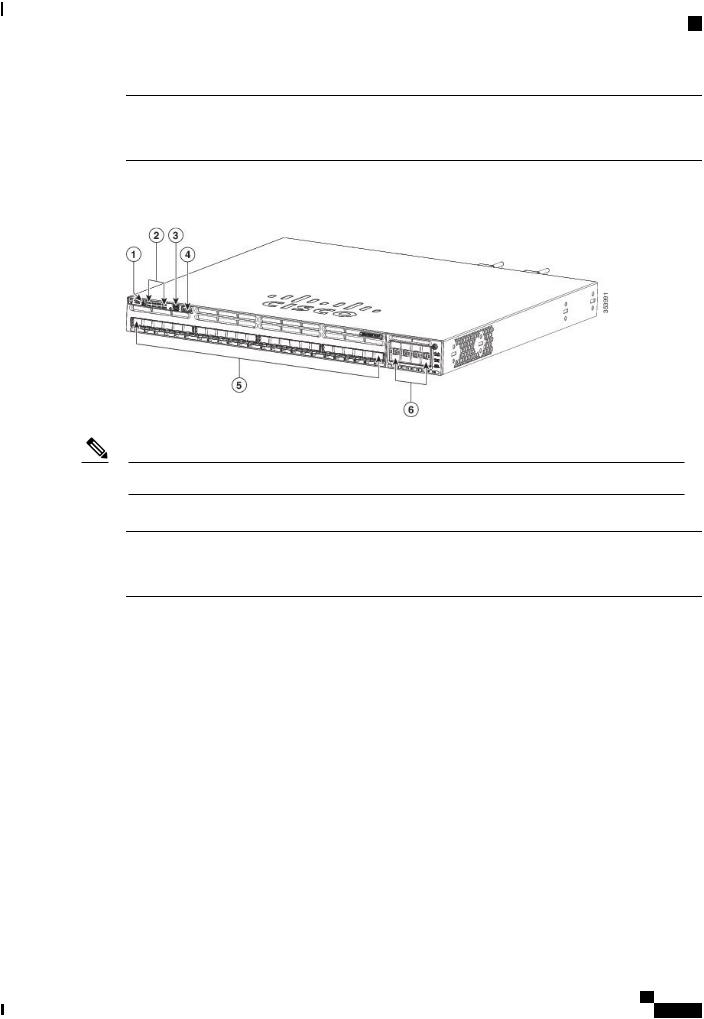
Figure 1: WS-C3850-48P-L Switch Front Panel
1 |
Mode button |
4 |
USB mini-Type B (console) port |
2 |
Status LEDs |
5 |
10/100/1000 PoE+ ports |
3 |
USB Type A storage port |
6 |
Network module |
Figure 2: WS-C3850-24S Switch Front Panel
Note The WS-C3850-12S switches have similar front panels.
1 |
UID button |
5 |
USB Type A storage port |
2 |
Mode button |
6 |
SFP module slots (downlink) |
Catalyst 3850 Switch Hardware Installation Guide
6 |
OL-26779-05 |
Product Overview
10/100/1000 Ports
3 Status LEDs |
7 Network module |
4USB mini-Type B (console) port
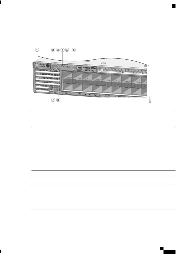
Figure 3: WS-C3850-24XS-E Switch Front Panel
Note The WS-C3850-24XS-E switches have the following components.
1 |
Mode button |
4 |
USB mini-Type B (console) port |
2 |
Status LEDs |
5 |
10 G SFP+ ports |
3 |
USB Type A storage port |
6 |
Network module |
10/100/1000 Ports
The 10/100/1000 ports use RJ-45 connectors with Ethernet pinouts. The maximum cable length is 328 feet (100 meters). The 10BASE-T, 100BASE-TX, 1000BASE-T traffic requires Category 5 or Category 5e twisted pair (UTP) cable. The 10BASE-T traffic can use Category 3 or Category 4 UTP cable.
PoE, PoE+, and Cisco UPoE Ports
The PoE+ and Cisco Universal Power Over Ethernet (Cisco UPoE) ports use the same connectors as described in 10/100/1000 Port Connections, on page 50. They provide:
•PoE+ ports: Support for IEEE 802.3af-compliant powered devices (up to 15.4 W PoE per port) and support for IEEE 802.3at-compliant powered devices (up to 30 W PoE+ per port). The maximum total PoE power in a 1RU switch is 1800 W.
•Support for Cisco-enhanced PoE.
Catalyst 3850 Switch Hardware Installation Guide
OL-26779-05 |
7 |

Product Overview
SFP and QSFP Module Slots
•Support for prestandard Cisco powered devices.
•Configuration for StackPower. When the switch internal power supply module(s) cannot support the total load, StackPower configurations allow the switch to leverage power available from other switches.
•Configurable support for Cisco intelligent power management, including enhanced power negotiation, power reservation, and per-port power policing.
Depending on the installed power supply modules, each port can deliver up to 60 W of Cisco UPOE. See the Power Supply Modules, on page 26 for the power supply matrix that defines the available PoE, PoE+, and Cisco UPOE power per port. The output of the PoE+ circuit has been evaluated as a Limited Power Source (LPS) per IEC 60950-1.
Note Restrictions for the WS-C3850-12X48U-L, WS-C3850-12X48U-S and WS-C3850-12X48U-E switch models:
•A maximum of 28 ports are available for UPoE connections. This is because some power from the power supplies is diverted to the switch, and only the remaining power is transmitted to the ports.
SFP and QSFP Module Slots
The uplink and downlink ports for the Catalyst WS-C3850 switch models are as follows.
•The downlink ports on the Catalyst WS-C3850-12S and WS-C3850-24S switch models support standard SFP modules.
•The downlink ports on the Catalyst WS-C3850-12XS and WS-C3850-24XS switch models support standard SFP+ modules.
•The10GdownlinkportsontheCatalystWS-C3850-48XS-S,WS-C3850-48XS-F-S,WS-C3850-48XS-E and WS-C3850-48XS-F-E switch models support standard SFP+ modules.
•The40GdownlinkportsontheCatalystWS-C3850-48XS-S,WS-C3850-48XS-F-S,WS-C3850-48XS-E and WS-C3850-48XS-F-E switch models support standard QSFP modules.
For supported SFP modules, refer to the Cisco Transceiver Modules Compatibility Information at http:// www.cisco.com/en/US/products/hw/modules/ps5455/products_device_support_tables_list.html
Note For information about the (uplink) SFP module slots on the network modules, see Network Modules, on page 10.
Management Ports
The management ports connect the switch to a PC running Microsoft Windows or to a terminal server.
•Ethernet management port. See Ethernet Management Port, on page 31.
•RJ-45 console port (EIA/TIA-232). See RJ-45 Console Port, on page 32.
Catalyst 3850 Switch Hardware Installation Guide
8 |
OL-26779-05 |
Product Overview
USB Type A Port
• USB mini-Type B console port (5-pin connector).
The 10/100/1000 Ethernet management port connection uses a standard RJ-45 crossover or straight-through cable. The RJ-45 console port connection uses the supplied RJ-45-to-DB-9 female cable. The USB console port connection uses a USB Type A to 5-pin mini-Type B cable. The USB console interface speeds are the same as the RJ-45 console interface speeds.
If you use the USB mini-Type B console port, the Cisco Windows USB device driver must be installed on any PC connected to the console port (for operation with Microsoft Windows). Mac OS X or Linux do not require special drivers.
The 4-pin mini-Type B connector resembles the 5-pin mini-Type B connectors. They are not compatible. Use only the 5-pin mini-Type B.
This illustration shows a 5-pin mini-Type B USB port.
Figure 4: USB Mini-Type B Port
With the Cisco Windows USB device driver, you can connect and disconnect the USB cable from the console port without affecting Windows HyperTerminal operations.
The console output always goes to both the RJ-45 and the USB console connectors, but the console input is active on only one of the console connectors at any one time. The USB console takes precedence over the RJ-45 console. When a cable is connected into the USB console port, the RJ-45 console port becomes inactive. Conversely, when the USB cable is disconnected from the USB console port, the RJ-45 port becomes active.
You can use the command-line interface (CLI) to configure an inactivity timeout which reactivates the RJ-45 console if the USB console has been activated and no input activity has occurred on the USB console for a specified time.
After the USB console deactivates due to inactivity, you cannot use the CLI to reactivate it. Disconnect and reconnect the USB cable to reactivate the USB console. For information on using the CLI to configure the USB console interface, see the software guide.
USB Type A Port
The USB Type A port provides access to external USB flash devices (also known as thumb drives or USB keys) and to specific Cisco USB Bluetooth devices.
The port supports Cisco USB flash drives with capacities from 128 MB to 8 GB (USB devices with port densities of 128 MB, 256 MB, 1 GB, 4 GB, and 8 GB are supported). When combined with stacking, you can upgrade other switches in the stack from an USB key inserted in any switch within the stack. Cisco IOS software provides standard file system access to the flash device: read, write, erase, and copy, as well as the ability to format the flash device with a FAT file system.
It provides you with the ability to automatically upgrade the internal flash with the USB drive's configuration and image for emergency switch recovery using USB auto-upgrade. This feature checks the internal flash for a bootable image and configuration and if either image or the configuration is not available, then the USB drive is checked for boot images and configuration. If the boot image and configuration are available, these are copied to flash for the reboot.
Catalyst 3850 Switch Hardware Installation Guide
OL-26779-05 |
9 |
Product Overview
Network Modules
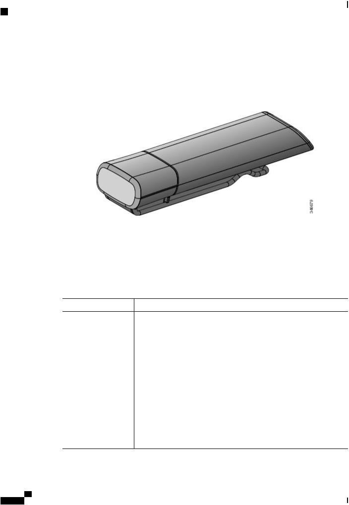
The port supports Cisco USB Bluetooth devices. The USB Bluetooth device acts as a Bluetooth host and serves as either a serial port or a management port connection. You can pair it with your Bluetooth smart phone, laptop, or tablet. If you configure the serial profile on the Bluetooth device, the switch turns the USB port into a serial port. If you configure the Personal Area Network (PAN) profile on the Bluetooth device, the switch turns the USB port into a management interface.
Figure 5: Cisco USB Bluetooth
Network Modules
The switch supports one hot-swappable network module that provides uplink ports to connect to other devices. The switch should only be operated with either a network module or a blank module installed.
The switch generates logs when you insert or remove a network module with SFP ports.
Table 2: Network Modules |
|
|
Network Module5 |
Description |
|
C3850-NM-4-1G |
This module has four 1 G SFP module slots. Any combination of standard SFP |
|
|
modules are supported. SFP+ modules are not supported. |
|
|
If you insert an SFP+ module in the 1 G network module, the SFP+ module does |
|
|
not operate, and the switch logs an error message. |
|
|
Note |
This is supported on the following switch |
|
|
models: |
• WS-C3850-24T/P/U
• WS-C3850-48T/F/P/U
• WS-C3850-12X48U
• WS-C3850-24XU
• WS-C3850-12S
• WS-C3850-24S
Catalyst 3850 Switch Hardware Installation Guide
10 |
OL-26779-05 |

Product Overview
Network Modules
Network Module5 |
Description |
|
C3850-NM-2-10G |
This module has four slots: |
|
|
Two slots (left side) support only 1 G SFP modules and two slots (right side) |
|
|
support either 1 G SFP or 10 G SFP modules. |
|
|
Note |
This is supported on the following switch |
models:
|
• WS-C3850-24T/P/U |
|
• WS-C3850-48T/F/P/U |
|
• WS-C3850-12X48U |
|
• WS-C3850-24XU |
|
• WS-C3850-12S |
|
• WS-C3850-24S |
C3850-NM-4-10G |
This module has four 10 G slots or four 1 G slots. |
|
Note This is supported on the following switch |
|
models: |
|
• WS-C3850-48T/F/P/U |
|
• WS-C3850-12X48U |
|
• WS-C3850-24XU |
|
• WS-C3850-12XS |
|
• WS-C3850-24XS |
C3850-NM-8-10G |
This module has eight 10 G slots with an SFP+ port in each slot. Each port |
|
supports a 1 G or 10 G connection |
|
Note This is supported on the following switch |
|
models: |
|
• WS-C3850-12X48U |
|
• WS-C3850-24XU |
|
• WS-C3850-24XS |
C3850-NM-2-40G This module has two 40 G slots with a QSFP+ connector in each slot.
Note This is supported on the following switch models:
•WS-C3850-12X48U
•WS-C3850-24XU
•WS-C3850-24XS
Catalyst 3850 Switch Hardware Installation Guide
OL-26779-05 |
11 |

Product Overview
LEDs
Network Module5 |
Description |
C3850-NM-BLANK |
Insert this blank module when the switch has no uplink ports (this is required |
|
for sufficient air flow). |
5 All network modules are hot-swappable.
For information about the network modules, see the Installing Network Modules, on page 59. For cable specifications, see Cables and Adapters, on page 103.
SFP and SFP+ Modules
The SFP and SFP+ modules provide copper or fiber-optic connections to other devices. These transceiver modules are field-replaceable, and they provide the uplink interfaces (expect in the fixed SFP slots in the WS-C3850-12S and WS-C3850-24S switches) when installed in an SFP module slot. The SFP modules have LC connectors for fiber-optic connections or RJ-45 connectors for copper connections.
Note The downlink ports on the Catalyst WS-C3850-12S and WS-C3850-24S switch models support standard SFP modules, and the downlink ports on the Catalyst WS-C3850-12XS and WS-C3850-24XS switch models support standard SFP+ modules.
Use only Cisco SFP and SFP+ modules on the switch. For the latest information about supported SFP and SFP+ modules, refer to the Cisco Transceiver Modules Compatibility Information at http://www.cisco.com/ en/US/products/hw/modules/ps5455/products_device_support_tables_list.html
For information about SFP modules, see the documentation at Installing SFP and SFP+ Modules, on page 65.
The Catalyst 3850 switch supports the SFP module patch cable (CAB-SFP-50CM), a 0.5-meter, copper, passive cable with SFP module connectors at each end. This cable is only used with 1-Gigabit Ethernet SFP ports to connect two Catalyst 3850 switches in a cascaded configuration.
For information about QSFP modules, see the documentation at
•QSFP Port Cabling Specifications
•Cisco S-Class 40GBASE QSFP Modules Data Sheet
LEDs
You can use the switch LEDs to monitor switch activity and its performance.
Note Catalyst 3850 switches might have slight cosmetic differences on the bezels.
Catalyst 3850 Switch Hardware Installation Guide
12 |
OL-26779-05 |
Product Overview
LEDs
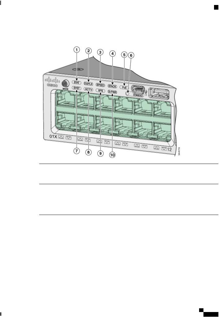
This figure shows the switch LEDs and the Mode button that you use to select a port mode.
Figure 6: Switch Front Panel LEDs
1 |
STAT (status) |
6 |
USB mini-Type B console port LED |
2 |
DUPLX (duplex) |
7 |
SYST (system) |
3 |
SPEED |
8 |
ACTV (active) |
4 |
STACK |
9 |
XPS 6 |
5 |
PoE 7 |
10 |
S-PWR (StackPower) |
6 XPS = expandable power system.
Catalyst 3850 Switch Hardware Installation Guide
OL-26779-05 |
13 |

Product Overview
LEDs
7 Only on switch models that support PoE.
Figure 7: Switch Front Panel LEDs for the WS-C3850-12S, WS-C3850-24S, WS-C3850-12XS, and WS-C3850-24XS Switches
1 |
UID (blue beacon) |
6 |
USB mini-Type B console port LED |
2 |
STAT (status) |
7 |
SYST (system) |
3 |
DUPLX (duplex) |
8 |
ACTV (active) |
4 |
SPEED |
9 |
XPS 8 |
5 |
STACK |
10 |
S-PWR (StackPower) |
Catalyst 3850 Switch Hardware Installation Guide
14 |
OL-26779-05 |
Product Overview
LEDs
8 XPS = expandable power system.
Figure 8: Switch Front Panel LEDs for the WS-C3850-48XS Switches
1 |
UID (blue beacon) |
5 |
STACK |
2 |
STAT (status) |
6 |
USB mini-Type B console port LED |
3 |
DUPLX (duplex) |
7 |
SYST (system) |
4 |
SPEED |
8 |
ACTV (active) |
SYST LED
Table 3: SYST LED |
|
Color |
System Status |
Off |
System is not powered on. |
Green |
System is operating normally. |
Blinking green |
POST in progress. |
Amber |
System is receiving power but is not functioning properly. |
Catalyst 3850 Switch Hardware Installation Guide
OL-26779-05 |
15 |

Product Overview
LEDs
Color |
System Status |
Blinking amber |
There is a fault with one of the following: |
|
• Network module (non traffic-related) |
|
• Power supply |
|
• Fan module |
XPS LED
Table 4: XPS LED |
|
Color |
Description |
Off |
XPS cable is not installed. |
|
Switch is in StackPower mode. |
Green |
XPS is connected and ready to provide back-up power. |
Blinking green |
XPS is connected but is unavailable because it is providing power to another device |
|
(redundancy has been allocated to a neighboring device). |
Amber |
The XPS is in standby mode or in a fault condition. See the XPS 2200 |
|
documentation for information about the standby mode and fault conditions. |
Blinking amber |
The power supply in a switch has failed, and the XPS is providing power to that |
|
switch (redundancy has been allocated to this device). |
For information about the XPS 2200, see the Cisco eXpandable Power System 2200 Hardware Installation Guide on Cisco.com:
http://www.cisco.com/go/xps2200_hw
Port LEDs and Modes
Each Ethernet port, 1-Gigabit Ethernet module slot, and 10-Gigabit Ethernet module slot has a port LED. These port LEDs, as a group or individually, display information about the switch and about the individual ports. The port mode determines the type of information shown by the port LEDs.
To select or change a mode, press the Mode button until the desired mode is highlighted. When you change port modes, the meanings of the port LED colors also change.
When you press the Mode button on any switch in the switch stack, all the stack switches change to show the same selected mode. For example, if you press the Mode button on the active switch to show the SPEED LED, all the other switches in the stack also show the SPEED LED.
Catalyst 3850 Switch Hardware Installation Guide
16 |
OL-26779-05 |

Product Overview
LEDs
Table 5: Port Mode LEDs |
|
|
Mode LED |
Port Mode |
Description |
STAT |
Port status |
The port status. This is the default mode. |
SPEED |
Port speed |
The port operating speed: 10, 100, or 1000 Mb/s. |
DUPLX |
Port duplex mode |
The port duplex mode: full duplex or half duplex. |
ACTV |
Active |
The active switch status. |
STACK |
Stack member status |
Stack member status. |
|
StackWise port status |
The StackWise port status. See STACK LED, on page |
|
|
20. |
PoE9 |
The PoE+ port status. |
The PoE+ port status. |
9 Only switches with PoE+ ports.
Table 6: Meaning of Switch LED Colors in Different Modes
Port Mode |
Port LED Color |
Meaning |
STAT (port status) |
Off |
No link, or port was administratively shut down. |
|
Green |
Link present, no activity. |
|
Blinking green |
Activity. Port is sending or receiving data. |
|
Alternating green-amber |
Link fault. Error frames can affect connectivity, and errors |
|
|
such as excessive collisions, CRC errors, and alignment |
|
|
and jabber errors are monitored for a link-fault indication. |
|
Amber |
Port is blocked by Spanning Tree Protocol (STP) and is |
|
|
not forwarding data. |
|
|
After a port is reconfigured, the port LED can be amber |
|
|
for up to 30 seconds as STP checks the switch for possible |
|
|
loops. |
Catalyst 3850 Switch Hardware Installation Guide
OL-26779-05 |
17 |

Product Overview
LEDs
Port Mode |
Port LED Color |
Meaning |
SPEED |
10/100/1000/SFP ports |
|
|
Off |
Port is operating at 10 Mb/s. |
|
Green |
Port is operating at 100 Mb/s. |
|
Single green flash (on for |
Port is operating at 1000 Mb/s. |
|
100 ms, off for 1900 ms) |
|
|
Blinking twice |
Port is operating at 2500, 5000 or 10000 Mb/s |
|
Network module slots |
|
|
|
Off |
Port is not operating. |
|
|
Blinking green |
Port is operating at up to 10 Gb/s. |
|
DUPLX (duplex) |
Off |
Port is operating in half duplex. |
|
|
Green |
Port is operating in full duplex. |
|
ACTV (data active |
Off |
The switch is not the active switch. |
|
switch) |
|
Note |
For a standalone switch, this LED is |
|
|
|
off. |
|
Green |
The switch is the active switch. |
|
|
Amber |
Error during active switch election. |
|
|
Blinking green |
Switch is a standby member of a data stack and assumes |
|
|
|
active responsibilities if the current active switch fails. |
|
STACK (stack |
Off |
No stack member corresponding to that member number. |
|
member) |
Blinking green |
Stack member number. |
|
|
|||
|
Green |
Member numbers of other stack member switches. |
|
Catalyst 3850 Switch Hardware Installation Guide
18 |
OL-26779-05 |
Loading...