


 Loading...
GETTING STARTED GUIDE
Catalyst 3560-E Switch Getting Started Guide
INCLUDING LICENSE AND WARRANTY
1About this Guide
2Taking Out What You Need
3Running Express Setup
4Managing the Switch
5Rack-Mounting
6Connecting to the Switch Ports
7In Case of Difficulty
8Obtaining Documentation, Obtaining Support, and Security Guidelines
9Cisco 90-Day Limited Hardware Warranty Terms
1 About this Guide
This guide provides instructions on how to use Express Setup to initially configure your Catalyst switch. Also covered are switch management options, basic rack-mounting procedures, port and module connection procedures, and troubleshooting help.
For additional installation and configuration information for Catalyst 3560-E switches, see the Catalyst 3560-E documentation on Cisco.com. For system requirements, important notes, limitations, open and resolved bugs, and last-minute documentation updates, see the release notes, also on Cisco.com.
When using the online publications, refer to the documents that match the Cisco IOS software version running on the switch. The software version is on the Cisco IOS label on the switch rear panel.
You can order printed copies of the manuals from the Cisco.com sites and from the telephone numbers listed in the “Obtaining Documentation, Obtaining Support, and Security Guidelines” section on page 21.
For translations of the warnings that appear in this publication, see the Regulatory Compliance and Safety Information for the Catalyst 3750-E and Catalyst 3560-E Switch that accompanies this guide.
2 Taking Out What You Need
Follow these steps:
1.Unpack and remove the switch and the accessory kit from the shipping box.
2.Return the packing material to the shipping container, and save it for future use.
3.Verify that you have received the items shown on page 3. If any item is missing or damaged, contact your Cisco representative or reseller for instructions.
Some switch models might include additional items that are not shown on page 3.
4.For switches with the optional 1150-W power supply module (model C3K-PWR-1150WAC), install the power supply in the switch as described in the installation notes after you rack-mount the switch.
2

Shipping Box Contents
 SYST RPS MASTR STAT DUPLX SPEED STACK PoE MODE
1 |
2 |
|
|
Cisco |
|
|
Documentation |
|
|
CD |
Product |
Catalyst 3560-E
PoE-48
3 |
4 |
5 |
6 |
7 |
8 |
|
|
|
9 |
10 |
|
11 |
12 |
|
|
|
|
|
200048 |
1 |
Catalyst switch1 |
|
7 |
Four rubber mounting feet |
|
2 |
Documentation |
|
8 |
Power cord retainer |
|
3 |
AC power cord |
|
9 |
Twelve number-8 Phillips flat-head screws |
|
4 |
Console cable |
|
10 |
Four number-12 Phillips machine screws |
|
5 |
Two 19-inch mounting brackets |
11 |
One black Phillips machine screw |
||
6 |
Cable guide |
|
12 |
Ground lug screw and ring terminal |
|
1. Catalyst 3560E-48 Power over Ethernet (PoE) switch shown for example. Your switch model might look different.
3

3 Running Express Setup
When you first set up the switch, you should use Express Setup to enter the initial IP information. Doing this enables the switch to connect to local routers and the Internet. You can then access the switch through the IP address for further configuration.
You need this equipment to set up the switch:
•A PC with Windows 2000 or XP installed
•A web browser (Internet Explorer 5.5, 6.0, Netscape 7.1 or later) with JavaScript enabled
•A straight-through or crossover Category 5 Ethernet cable to connect your PC to the switch
Disable any pop-up blockers or proxy settings in your browser software and any wireless client running on your PC.
As an example, the Express Setup illustrations show the Catalyst 3560E-48 PoE switch. You can run Express Setup on all Catalyst 3560-E switch models.
To run Express Setup:
Step 1 Make sure that nothing is connected to the switch.
During Express Setup, the switch acts as a DHCP server. If your PC has a static IP address, change your PC settings before you begin to temporarily use DHCP.
Catalyst 3560-E
Step 2 Power the switch.
For AC-powered switches, connect the AC power cord to the switch power supply and to a grounded AC outlet.
For DC-powered switches, see the wiring instructions in the hardware installation guide on Cisco.com.
Step 3 When the switch powers on, it begins the power-on self-test (POST). During POST, the LEDs blink while tests verify that the switch functions properly.
Wait for the switch to complete POST, which can take several minutes.
Step 4 Verify that POST has completed by confirming that the SYST LED remains green. If the switch fails POST, the SYST LED turns amber. See the “In Case of Difficulty” section on page 19 if your switch fails POST.
4

Step 5 Press and hold the Mode button for
3 seconds. When all of the LEDs above the Mode button turn green, release the Mode button.
 SYST
SYST
RPS


 STAT
STAT
DUPLX


SPEED
 PoE
PoE
Catalyst 3560-E
Step 6 If the LEDs above the Mode button blink after you press the button, release it. Blinking LEDs mean that the switch is already configured and cannot go into Express Setup mode. For more information, see the “Resetting the Switch” section on page 20.
Step 7 Verify that the switch is in Express Setup mode. Make sure that all LEDs above the Mode button are green. (On some switch models, the RPS LED remains off.)
Step 8 Connect a Category 5 Ethernet cable to one of these locations:
• Any 10/100/1000 Ethernet port on the switch front panel (for switches with front-panel Ethernet ports).
• The Ethernet management port on the switch rear panel.
Connect the other end of the cable to the
Ethernet port on your PC.
Step 9 Verify that the LEDs on both Ethernet ports are green.
Wait 30 seconds.
Step 10 Launch a web browser on your PC. Enter the IP address 10.0.0.1 in the web browser, and press Enter.
5
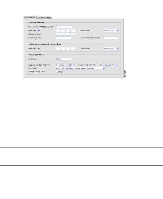
Step 11 The Express Setup Basic Settings page appears. If it does not appear, see the “In Case of Difficulty” section on page 19.
Step 12 Enter this information in the Network Settings fields:
•In the Management Interface (VLAN ID) field, the default is 1. Enter a new VLAN ID only if you want to change the management interface through which you manage the switch. The VLAN ID range is 1 to 1001.
•In the IP Address field, enter the IP address of the switch. In the Subnet Mask field, click the drop-down arrow, and select a Subnet Mask.
•In the Default Gateway field, enter the IP address for the default gateway (router).
•Enter your password in the Switch Password field. The password can be from 1 to 25 alphanumeric characters, can start with a number, is case sensitive, allows embedded spaces, but does not allow spaces at the beginning or end. In the Confirm Switch Password field, enter your password again.
Step 13 (Optional) Enter this information in the Ethernet Management Port Settings fields:
In the IP Address field, enter the IP address of the Ethernet management port. In the Subnet Mask field, click the drop-down arrow, and select a Subnet Mask.
Step 14 (Optional) You can enter the Optional Settings information now or enter it later by using the device manager interface:
•In the Host Name field, enter a name for the switch. The host name is limited to 31 characters; embedded spaces are not allowed.
•Enter the date, time, and time zone information in the System Date, System Time, and Time Zone fields. Click Enable to enable daylight saving time.
6

Step 15 (Optional) You can select the Advanced Settings tab on the Express Setup window and enter the advanced settings now or enter them later by using the device manager interface.
Step 16 (Optional) Enter this information in the Advanced Setting fields:
•In the Telnet Access field, click Enable if you are going to use Telnet to manage the switch by using the command-line interface (CLI). If you enable Telnet access, you must enter a Telnet password.
•In the Telnet Password field, enter a password. The Telnet password can be from 1 to 25 alphanumeric characters, is case sensitive, allows embedded spaces, but does not allow spaces at the beginning or end. In the Confirm Telnet Password field, re-enter the Telnet password.
•In the SNMP field, click Enable to enable Simple Network Management Protocol (SNMP). Enable SNMP only if you plan to manage switches by using CiscoWorks 2000 or another SNMP-based network-management system.
•If you enable SNMP, you must enter a community string in the SNMP Read Community field, the SNMP Write Community field, or both. SNMP community strings authenticate access to MIB objects. Embedded spaces are not allowed in SNMP community strings. When you set the SNMP read community, you can access SNMP information, but you cannot change it. When you set the SNMP write community, you can both access and change SNMP information.
•In the System Contact and System Location fields, enter a contact name and the wiring closet, floor, or building where the switch is located.
Step 17 (Optional) You can enable IPv6 on the switch in the Advanced Settings window. In the Enable IPv6 field, click Enable. Note: Enabling IPv6 restarts the switch when you complete Express Setup.
7

Step 18 To complete Express Setup, click Submit in the Network Settings or the Advanced Settings window to save your settings. Click Cancel to clear your settings.
When you click Submit, the switch is configured and exits Express Setup mode. The PC displays a warning message and then tries to connect with the new switch IP address. If you configured the switch with an IP address that is in a different subnet from the PC, connectivity between the PC and the switch is lost. If you enabled IPv6, the switch restarts.
Step 19 Disconnect the switch from the PC, and install the switch in your production network. See the “Managing the Switch” section on page 8 for information about configuring and managing the switch.
If you need to rerun Express Setup, see the “Resetting the Switch” section on page 20.
Refreshing the PC IP Address
After you complete Express Setup, you should refresh the PC IP address:
•For a dynamically assigned IP address, disconnect the PC from the switch, and reconnect the PC to the network. The network DHCP server assigns a new IP address to the PC.
•For a statically assigned IP address, change it to the previously configured IP address.
4 Managing the Switch
After you complete Express Setup and install the switch in your network, use the device manager or other management options described in this section for further configuration.
Using the Device Manager
The simplest way to manage the switch is by using the device manager that is in the switch memory. This is a web interface that offers quick configuration and monitoring. You can access the device manager from anywhere in your network through a web browser.
Follow these steps:
1.Launch a web browser on your PC or workstation.
2.Enter the switch IP address in the web browser, and press Enter. The device manager page appears.
3.Use the device manager to perform basic switch configuration and monitoring. Refer to the device manager online help for more information.
4.For more advanced configuration, download and run the Cisco Network Assistant, which is described in the next section.
8
Loading...